First published on TechNet on Jul 16, 2009 Ned-san here again. Customers frequently call us about configuring their servers to listen over specific network ports. This is usually to satisfy firewall rules – more on this later. A port in TCP/IP is simply an endpoint to communication between computers. Some are reserved, some are well-known, and the rest are simply available to any application to use. Today I will explain the network communication done through all facets of DFSR operation and administration. Even if you don’t care about firewalls and ports, this should shed some light on DFSR networking in general, and may save you skull sweat someday.
DFSR and RPC
Plenty of Windows components support hard-coding to exclusive ports, and at a glance, DFSR is no exception. By running the DFSRDIAG STATICRPC command against the DFSR servers you force them to listen on whatever port you like for file replication:
Many Windows RPC applications use the Endpoint Mapper (EPM) component for these types of client-server operations. It’s not a requirement though; an RPC application is free to declare its own port and only listen on that one, with a client that is hard-coded to contact that port only. This range of ports is 1025-5000 in Windows Server 2003 and older, and 49152-65535 in Vista and … DFSR uses EPM.
Update 3/3/2011 (nice catch Walter)
As you have probably found, we later noticed a bug in DFSR on Win2008 and Win2008 R2 DCs (only – not member servers) where the service would always send-receive on port 5722. This article was done before that and doesn’t reflect it. Read more on this here:
By setting the port, you are telling EPM to always respond with the same port instead of one within the dynamic range. So when DFSR contacted the other server, it would only need to use two ports:
So with a Netmon 3.3 capture, it will look something like this when the DFSR service starts up:
1. The local computer opens a dynamic client port and connects to EPM on the remote computer, asking for connectivity to DFSR.
2. That remote computer responds with a port that the local computer can connect to for DFSR communication. Because I have statically assigned port 55555, the remote computer will always respond with this port.
3. The local computer then opens a new client port and binds to that RPC port on the remote server, where the DFSR service is actually listening. At this point two DFSR servers can replicate files between each other.
The Rest of the Story
If it’s that easy, why the blog post? Because there’s much more DFSR than just the RPC replication port. To start, your DFSR servers need to be able to contact DC’s. To do that, they need name resolution. And they will need to use Kerberos. And the management tools will need DRS API connectivity to the DC’s. There will also need to be SMB connectivity to create replicated folders and communicate with the Service Control Manager to manipulate DFSR. And all of the above also need the dynamic client ports available outbound through the firewall to allow that communication. So now that’s:
EPM port 135 (inbound on remote DFSR servers and DC’s)
DFSR port X (inbound on remote DFSR servers)
SMB port 445 (inbound on remote DFSR servers)
DNS port 53 (inbound on remote DNS servers)
LDAP port 389 (inbound on remote DC’s)
Kerberos port 88 (inbound on remote DC’s)
Ports 1025-5000 or 49152-65535 (outbound, Win2003 and Win2008 respectively – and inbound on remote DC’s).
Let’s see this in action. Here I gathered a Netmon 3.3 capture of configuring a new replication group:
Server-01 – IP 10.10.0.101 – DC/DNS
Server-02 – IP 10.10.0.102 – DFSR
Server-03 – IP 10.10.0.103 – DFSR
Server-04 – IP 10.10.0.104 – Computer running the DFSMGMT.MSC snap-in
1. First the snap-in gets name resolution for the DC from my management computer (local port 51562 to remote port 53):
2. Then it contacts the DC – the EPM is bound (local port 49199 to remote port 135) and a dynamic port is negotiated so that the client knows which port on which to talk to the DC (port 49156).
3. Having connected to the DC through RPC to DRS (a management API), it then returns information about the domain and other things needed by the snap-in.
4. The snap-in then performs an LDAP query to the DC to locate the DFSR-GlobalSettings container in that domain o that it can read in any new Replication Groups (local port 49201 to remote port 389).
5. The snap-performs LDAP and DNS queries to get the names of the computers being selected for replication:
6. The DFSR service must be verified (is it installed? Is it running?) This requires a Kerberos CIFS (SMB) request to the DC as well as an SMB connection to the DFSR servers – this is actually a ‘named pipe’ operation over remote port 445, where RPC uses SMB as a transport:
7. The Replicated Folders are created (or verified to exist) on the DFSR servers – I called mine ‘testrf’. This uses SMB again from the snap-in computer to the DFSR server, over remote port 445:
8. The snap-in will write all the configuration data through LDAP over remote port 389 against the DC. This creates all the AD objects and attributes, creates the topology, writes to each DFSR computer object, etc. There are quite a few frames here so I will just highlight a bit of it:
9. If you wait for AD replication to complete and the DFSR servers to poll for changes, you will see the DFSR servers request configuration info through LDAP, and then start working normally on their static RPC port 55555 – just like I showed at the beginning of this post above.
DCOM and WMI
All of the things I’ve discussed are guaranteed needs in order to use DFSR. For the most part you don’t have to have too many remote ports open on the DFSR server itself. However, if you want to use tools like DFSRDIAG.EXE and WMIC.EXE remotely against a DFSR server, or have a remote DFSR server generate ‘Diagnostic Health Reports’, there is more to do.
DFSR utilizes Windows Management Instrumentation as its ‘quasi-API’. When tools like DFS Management are run to generate health reports, or DFSRDIAG POLLAD is targeted against a remote server, you are actually using DCOM and WMI to tell the targeted server to perform actions on your behalf.
There is no mechanism to control which RPC DCOM/WMI will listen on as there is for DFSR and other services. At service startup DCOM/WMI will pick the next available dynamic RPC port. This means in theory that you would have to have open the entire range of dynamic ports for the target OS, 1025-5000 (Win2003) or 49152-65535 (Win2008)
For example, here I am running DFSRDIAG POLLAD /MEM:2008-02 to force that server to poll its DC for configuration changes. Note the listening port that I am talking to on the DFSR server (hint – it’s not 55555):
And in my final example, here I am running the DFS Management snap-in and requesting a diagnostic health report. Note again how we use DCOM/WMI/RPC and do not connect directly to the DFSR service; again this requires that we have all those inbound dynamic ports open on the DFSR server:
Wrap Up
So is it worth it to try and use a static replication port? Maybe. If you don’t plan on directly administering a DFSR server and just need it talking to its DC, its DNS server, and its replication partners, can definitely keep the number of ports used quite low. But if you ever want to communicate directly with it as an administrator, you will need quite a few holes punched through your firewall.
File shares are used in organizations to allow users to access and exchange files. If the number of file shares is large, it may be difficult to manage them because mapping many shared resources to each user’s computer takes time and effort. If the configuration of one file share changes, you need to update shared drive mappings for all users using this share. In this case, DFS can help you optimize the hierarchy of shared folders to streamline administration and the use of shared resources.
This blog post explains DFS configuration and how to set up DFS replication in Windows Server 2019.
NAKIVO for Windows Backup
Fast backup of Windows servers and workstations to onsite, offiste and cloud. Recovery of full machines and objects in minutes for low RTOs and maximum uptime.
A Distributed File System (DFS) is a logical organization that transparently groups existing file shares on multiple servers into a structured hierarchy. This hierarchy can be accessed using a single share on a DFS server. A DFS file share can be replicated across multiple file servers in different locations to optimize server load and increase access speed to shared files. In this case, a user can access a file share on a server that is closest to them. DFS is intended to simplify access to shared files.
DFS uses the Server Message Block (SMB) protocol, which is also known as the Common Internet File System (CIFS). Microsoft’s implementation of DFS doesn’t work with other file sharing protocols like NFS or HDFS. However, you can connect multiple SMB shares configured on NAS devices and Linux machines using Samba to your DFS server running on Windows Server. DFS consists of server and client components.
You can configure one DFS share that includes multiple file shares and connect users to this single file share using a unified namespace. When users connect to this file share using a single path, they see a tree structure of shared folders (as they are subfolders of the main share) and can access all needed file shares transparently. Underlying physical file servers hosting file shares are abstracted from the namespace used to access shares. DFS namespaces and DFS replication are the two main components used for DFS functioning.
What is a DFS namespace?
A DFS namespace is a virtual folder that contains links to shared folders stored on different file servers. DFS namespaces can be organized in different ways depending on business needs. They can be organized by geographical location, organization units, a combination of multiple parameters, etc. You can configure multiple namespaces on a DFS server. A DFS namespace can be standalone or domain-based.
A standalone DFS namespace stores configuration information and metadata locally on a root server in the system registry. A path to access the root namespace is started with the root server name. A standalone DFS namespace is located only on one server and is not fault-tolerant. If a root server is unavailable, the entire DFS namespace is unavailable. You can use this option if you don’t have an Active Directory domain configured (when using a Workgroup).
A domain-based DFS namespace stores configuration in Active Directory. A path to access a root namespace starts with the domain name. You can store a domain-based DFS namespace on multiple servers to increase the namespace availability. This approach allows you to provide fault tolerance and load balancing across servers. Using domain-based DFS namespaces is recommended.
A namespace consists of the root, links (folders), and folder targets.
A namespace root is a starting point of a DFS namespace tree. Depending on the type, a namespace can look like this:
\\ServerName\RootName (a standalone namespace)
\\DomainName\RootName (a domain-based namespace)
A namespace server is a physical server (or a VM) that hosts a DFS namespace. A namespace server can be a regular server with the DFS role installed or a domain controller.
A folder is a link in a DFS namespace that points to a target folder containing content for user access. There are also folders without targets used for organizing the structure.
A folder target is a link to a shared file resource located on a particular file server and available via the UNC path (Universal Naming Convention). A folder target is associated with the folder in a DFS namespace, for example, \\FS2\TestShare on the FS2 server. A folder target is what users need to access files.
One folder target can be a link to a single folder or multiple folders (if these folders are located on two different servers and are synchronized/replicated with each other). For example, a user needs to access \\DFS-server01\TestShare\Doc but depending on the user’s location, the user is redirected to a shared folder \\FS01\Doc or \\FS02\Doc.
The DFS tree structure includes the following components:
DFS root, which is a DFS server on which the DFS service is running
DFS links, which are links pointing to network shares used in DFS
DFS targets, which are real network shares to which DFS links point
What is DFS replication?
DFS replication is a feature used to duplicate existing data by replicating copies of that data to multiple locations. Physical file shares can be synchronized with each other at two or more locations.
An important feature of DFS replication is that the replication of a file starts only after that file has been closed. For this reason, DFS replication is not suitable for replicating databases, given that databases have files opened during the operation of a database management system. DFS replication supports multi-master replication technology, and any member of a replication group can change data that is then replicated.
A DFS replication group is a group of servers participating in the replication of one or multiple replication folders. A replicated folder is synchronized between all members of the replication group.
DFS replication uses a special Remote Differential Compression algorithm that allows DFS to detect changes and copy only changed blocks of files instead of copying all data. This approach allows you to save time and reduce replication traffic over the network.
DFS replication is performed asynchronously. There can be a delay between writing changes to the source location and replicating those changes to the target location.
DFS Replication topologies
There are two main DFS replication topologies:
Hub and spoke. This topology requires at least three replication members: one which acts as a hub and two others act as spokes. This technique is useful if you have a central source originating data (hub) and you need to replicate this data to multiple locations (spokes).
Full mesh. Each member of a replication group replicates data to each group member. Use this technique if you have 10 members or less in a replication group.
What are the requirements for DFS?
The main requirement is using Windows Server 2008 DataCenter or Enterprise editions, Windows Server 2012, or a newer Windows Server version. It is better to use Windows Server 2016 or Windows Server 2019 nowadays.
NTFS must be a file system to store shared files on Windows Server hosts.
If you use domain-based namespaces, all servers of a DFS replication group must belong to one Active Directory forest.
How to Set Up DFS in Your Windows Environment
You need to prepare at least two servers. In this example, we use two machines running Windows Server 2019, one of which is an Active Directory domain controller:
Server01-dc.domain1.local is a domain controller.
Server02.domain1.local is a domain member.
This is because configuring DFS in a domain environment has advantages compared to Workgroup, as explained above. The domain name is domain1.local in our case. If you use a domain, don’t forget to configure Active Directory backup.
Enable the DFS roles
First of all, you need to enable the DFS roles in Windows Server 2019.
Open Server Manager.
Click Add Roles and Features in Server Manager.
Select Role-based or featured-based installation in the Installation type screen of the Add Roles and Features wizard.
In the Server Selection screen, make sure your current server (which is a domain controller in our case) is selected. Click Next at each step of the wizard to continue.
Select server roles. Select DFS Namespaces and DFS Replication, as explained in the screenshot below.
In the Features screen, you can leave settings as is.
Check your configuration in the confirmation screen and if everything is correct, click Install.
Wait for a while until the installation process is finished and then close the window.
DFS Namespace Setup
Create at least one shared folder on any server that is a domain member. In this example, we create a shared folder on our domain controller. The folder name is shared01 (D:\DATA\shared01).
Creating a shared folder
Right-click a folder and, in the context menu, hit Properties.
On the Sharing tab of the folder properties window, click Share.
Share the folder with Domain users and set permissions. We use Read/Write permissions in this example.
Click Share to finish. Then you can close the network sharing options window.
Now the share is available at this address:
\\server01-dc\shared01
Creating a DFS namespace
Let’s create a DFS namespace to link shared folders in a namespace.
Press Win+R and run dfsmgmt.msc to open the DFS Management window. You can also run this command in the Windows command line (CMD).
As an alternative, you can click Start > Windows Administrative Tools > DFS Management.
In the DFS Management section, click New Namespace.
The New Namespace Wizard opens in a new window.
Namespace Server. Enter a server name. If you are not sure that the name is correct, click Browse, enter a server name and click Check Names. In this example, we enter the name of our domain controller (server01-dc). Click Next at each step of the wizard to continue.
Namespace Name and Settings. Enter a name for a namespace, for example, DFS-01. Click Edit Settings.
Pay attention to the local path of a shared folder. Change this path if needed. We use the default path in our example (C:\DFSRoots\DFS-01).
You need to configure access permissions for network users. Click Use custom permissions and hit Customize.
We grant all permissions for domain users (Full Control). Click Add, select Domain Users, select the appropriate checkboxes, and hit OK to save settings.
Namespace type. Select the type of namespace to create. We select Domain-based namespace and select the Enable Windows Server 2008 mode checkbox. Select this checkbox if the functional level of your domain is Windows Server 2008 when you use Windows Server 2016 or Windows Server 2019 for better compatibility.
It is recommended that you use a Domain-based namespace due to advantages such as high DFS namespace availability by using multiple namespace servers and transferring namespaces to other servers.
Review Settings. Review settings and, if everything is correct, click Create.
Confirmation. The window view in case of success is displayed in the screenshot below. The namespace creation has finished. Click Close.
Adding a new folder to a namespace
Now we need to add a new folder into the existing namespace. We are adding a folder on the same server, which is a domain controller, but this method is applicable for all servers within a domain.
Open the DFS management window by running dfsmgmt.msc as we did before. Perform the following actions in the DFS management window.
In the left pane, expand a namespace tree and select a namespace (\\domain1.local\DFS-01\ in our case).
In the right pane (the Actions pane), click New Folder.
In the New Folder window, enter a folder name, for example, Test-Folder to link the DFS folder and a shared folder created before. Click Add.
Enter the path to the existing folder. We use \\server01-dc\shared01 in this example. You can click Browse and select a folder. Click OK to save the path to the folder target.
The folder target has been added.
Click OK to save settings and close the New Folder window.
Now you can access the shared folder by entering the network address in the address bar of Windows Explorer:
\\server01-dc\dfs-01\Test-Folder
You should enter a path in the format:
\\DomainName\DFS-NameSpace\
How to Configure DFS Replication
We need to configure the second server to replicate data. The name of the second server is Server02 and this server is added to the domain1.local domain in this example. Add your second server to a domain if you have not done this operation before. Install the DFS roles, as we did for the first server. As an alternative method, you can use PowerShell instead of the Add Roles wizard. Run these two commands in PowerShell to install DFS replication and DFS namespace roles.
First of all, we need to install the DFS Replication role on the second server.
Create a folder for replicated data, for example, D:\Replication
We are going to use this folder to replicate data from the first folder created on the first server before.
Share this folder (D:\Replication) on the second server and configure access permissions the same way as for the previous shared folder. In this example, we share the folder with Domain Users and grant Read/Write permissions.
The network path is \\server02\replication in this example after sharing this folder. To check the network path to the folder, you can right-click the folder name and open the Sharing tab.
Let’s go back to the domain controller (server01-dc) and open the DFS Management window.
In the left pane of the DFS Management window, expand the tree and select the namespace created before (Test-Folder in this case).
Click Add Folder Target in the Actions pane located in the top right corner of the window.
The New Folder Target window appears. Enter the network path of the folder that was created on the second server before:
\\Server02\Replication
Click OK to save settings and close the window.
A notification message is displayed:
A replication group can be used to keep these folder targets synchronized. Do you want to create a replication group?
Click Yes.
Wait until the configuration process is finished.
As a result, you should see the Replicate Folder Wizard window. Perform the next steps in the wizard window.
Check the replication group name and replicated folder name. Click Next to continue.
Check folder paths in the Replication Eligibility screen.
Select the primary member from the drop-down list. In this example, the primary member is Server01-dc. Data from the primary member is replicated to other folders that are a part of the DFS namespace.
Select the topology of connections for replication.
Full mesh is the recommended option when using a DFS replication group with less than ten servers. We use Full mesh to replicate changes made on one server to other servers.
The No Topology option can be used if you want to create a custom topology after finishing the wizard.
The Hub and spoke option is inactive (grayed out) because we use less than three servers.
Configure replication group schedule and bandwidth. There are two options:
Replicate continuously using the specified bandwidth. Replication is performed as soon as possible. You can allocate bandwidth. Continuous replication of data that changes extensively can consume a lot of network bandwidth. To avoid a negative impact on other processes using the network, you can limit bandwidth for DFS replication. Keep in mind that hard disk load can be high.
Replicate during the specified days and times. You can configure the schedule to perform DFS replication at the custom date and time. You can use this option if you don’t need to always have the last version of replicated data in target folders.
We select the first option in our example.
Review settings for your DFS replication group. If everything is correct, click Create.
View the DFS replication configuration status on the Confirmation screen. You should see the Success status for all tasks as displayed on the screenshot below. Click Close to close the wizard window.
A notification message about the replication delay is displayed. Read the message and hit OK.
DFS replication has been configured. Open a shared folder from which data must be replicated initially. Write a file to that network folder and check whether the new data is replicated to the second folder on another server. Don’t forget that opened files are not replicated until they are closed after saving changes to a disk. In a few moments, you should see a file-replica in the target folder.
Using filters for DFS Replication
Use file filters to select the file types you don’t want to replicate. Some applications can create temporary files and replicating them wastes network bandwidth, loads hard disk drives, consumes additional storage space in the target folder, and increases overall time to replicate data. You can exclude the appropriate file types from DFS replication by using filters.
To configure filters, perform the following steps in the DFS Management window:
Expand the Replication tree in the navigation pane and select the needed DFS replication group folder name (domain1.local\dfs-01\Test-folder in our case).
Select the Replicated Folders tab.
Select the needed folder, right-click the folder name and hit Properties. Alternatively, you can select the folder and click Properties in the Actions pane.
Set the filtered file types by using masks in the folder properties window. In this example, files matching the rule are excluded from replication:
~*, *.bak, *.tmp
You can also filter subfolders, for example, exclude Temp subfolders from DFS replication.
Staging location
There can be a conflict when two or more users save changes to a file before these changes are replicated. The most recent changes have precedence for replication. Older versions of changed files are moved to the Conflict or Deleted folder. This issue can happen when replication speed is low and the file size is large (amount of changes is high) when the amount of time to transfer changed data is lower than the interval between writing changes to the file by users.
Staging folders act as a cache for new and changed files that are ready to be replicated from source folders to target folders. The staging location is intended for files that exceed a certain file size. Staging is used as a queue to store files that must be replicated and ensure that changes can be replicated without worrying about changes to them during the transfer process.
Another aspect of configuring staging folders is performance optimization. DFS replication can consume additional CPU and disk resources, slow down and even stop if the staging quota is too small for your tasks. The recommended size of the staging quota is equal to the size of the 32 largest files in the replication folder.
You can edit staging folder properties for DFS Replication in the DFS Management window:
Select a replication group in the left pane of the DFS Management window.
Select the Memberships tab.
Select the needed replication folder, right-click the folder, and hit Properties.
Select the Staging tab in the Properties window.
Edit the staging path and quota according to your needs.
Saved changes are not applied immediately. New staging settings must be replicated across all DFS servers within a domain. Time depends on Active Directory Domain Services replication latency and the polling interval of servers (5 minutes or more). Server reboot is not required.
DFS Replication vs. Backup
Don’t confuse DFS Replication of data in shared folders and data backup. DFS replication makes copies of data on different servers, but if unwanted changes are written to a file on one server, these changes are replicated to other servers. As a result, you don’t have a recovery point because the file has been overwritten with unwanted changes on all servers and you can use it for recovery in case of failure. This threat is present in case of a ransomware attack.
Use NAKIVO Backup & Replication to protect data stored on your physical Windows Server machines including data stored in shared folders. The product also supports Hyper-V VM backup and VMware VM backup at the host level for effective protection.
1 Year of Free Data Protection: NAKIVO Backup & Replication
Deploy in 2 minutes and protect virtual, cloud, physical and SaaS data. Backup, replication, instant recovery options.
Distributed File System (DFS) can significantly simplify shared resources management for administrators and make accessing shared folders more convenient for end-users. DFS makes transparent links to shared folders located on different servers.
DFS namespaces and DFS replication are two main features that you can configure in the DFS Management window after installing the appropriate Windows server roles. Opt for configuring DFS in a domain environment rather than in a Workgroup environment because there are many advantages, such as high availability and flexibility in an Active Directory domain.
First published on TechNet on Oct 06, 2008 Ned here again. Today I’m going to talk about a couple of scenarios we run into with the ConflictAndDeleted folder in DFSR. These are real quick and dirty, but they may save you a call to us someday.
Scenario 1: We need to empty out the ConflictAndDeleted folder in a controlled manner as part of regular administration (i.e. we just lowered quota and we want to reclaim that space).
Scenario 2: The ConflictAndDeleted folder quota is not being honored due to an error condition and the folder is filling the drive.
Let’s walk through these now.
Emptying the folder normally
It’s possible to clean up the ConflictAndDeleted folder through the DFSMGMT.MSC and SERVICES.EXE snap-ins, but it’s disruptive and kind of gross (you could lower the quota, wait for AD replication, wait for DFSR polling, and then restart the DFSR service). A much faster and slicker way is to call the WMI method CleanupConflictDirectory from the command-line or a script:
1. Open a CMD prompt as an administrator on the DFSR server. 2. Get the GUID of the Replicated Folder you want to clean:
WMIC.EXE /namespace:\\root\microsoftdfs path dfsrreplicatedfolderconfig get replicatedfolderguid,replicatedfoldername
(This is all one line, wrapped)
Example output:
3. Then call the CleanupConflictDirectory method:
WMIC.EXE /namespace:\\root\microsoftdfs path dfsrreplicatedfolderinfo where “replicatedfolderguid='<RF GUID>'” call cleanupconflictdirectory
Example output with a sample GUID:
WMIC.EXE /namespace:\\root\microsoftdfs path dfsrreplicatedfolderinfo where “replicatedfolderguid=’70bebd41-d5ae-4524-b7df-4eadb89e511e'” call cleanupconflictdirectory
4. At this point the ConflictAndDeleted folder will be empty and the ConflictAndDeletedManifest.xml will be deleted.
Emptying the ConflictAndDeleted folder when in an error state
We’ve also seen a few cases where the ConflictAndDeleted quota was not being honored at all. In every single one of those cases, the customer had recently had hardware problems (specifically with their disk system) where files had become corrupt and the disk was unstable – even after repairing the disk (at least to the best of their knowledge), the ConflictAndDeleted folder quota was not being honored by DFSR.
Here’s where quota is set:
Usually when we see this problem, the ConflictAndDeletedManifest.XML file has grown to hundreds of MB in size. When you try to open the file in an XML parser or in Internet Explorer, you will receive an error like “The XML page cannot be displayed” or that there is an error at line X . This is because the file is invalid at some section (with a damaged element, scrambled data, etc).
To fix this issue:
Follow steps 1-4 from above. This may clean the folder as well as update DFSR to say that cleaning has occurred. We always want to try doing things the ‘right’ way before we start hacking.
Stop the DFSR service.
Delete the contents of the ConflictAndDeleted folder manually (with explorer.exe or DEL).
Delete the ConflictAndDeletedManifest.xml file.
Start the DFSR service back up.
For a bit more info on conflict and deletion handling in DFSR, take a look at:
This article provides a resolution for the issue that the ConflictAndDeleted folder size may exceed its configured limitation.
Applies to: Windows Server 2016, Windows Server 2012 R2 Original KB number: 951010
Symptoms
In Windows Server, the size of the ConflictAndDeleted folder may exceed its configured limitation. By default, the limitation of the ConflictAndDeleted folder is 660 megabytes (MB). When this problem occurs, the ConflictAndDeleted folder may exhaust available disk space on the volume on which the folder resides. Additionally, the Distributed File System (DFS) Replication service cannot replicate any files.
Cause
This problem occurs because the ConflictAndDeletedManifest.xml file is corrupted. This file stores information about the current contents of the ConflictAndDeleted folder. The DFS Replication service writes to the ConflictAndDeletedManifest.xml file when files are added or removed from the ConflictAndDeleted folder.
Resolution
To resolve this problem, use WMIC commands to delete the contents of the ConflictAndDeleted folder and the ConflictAndDeletedManifest.xml file. Run the WMIC commands in a Command Prompt window (cmd.exe). To clean up the ConflictAndDeleted folder content of a replicated folder, run the following command:
ConsoleCopy
wmic /namespace:\\root\microsoftdfs path dfsrreplicatedfolderinfo where "replicatedfoldername='<ReplicatedFolderName>'" call cleanupconflictdirectory
Note
In this command, <ReplicatedFolderName> represents the name of the replicated folder.
To clean up the ConflictAndDeleted folder content of all of the replicated folders in a replication group, enter the following command:
ConsoleCopy
wmic /namespace:\\root\microsoftdfs path dfsrreplicatedfolderinfo where "replicationgroupname='<ReplicationGroupName>'" call cleanupconflictdirectory
Note
In this command,<ReplicationGroupName> represents the name of the replication group.
Note
If you have not run a WMIC command on the computer before, a short pause occurs while the computer installs WMIC.
Depending on the size of the ConflictAndDeleted folder, this process may take a few minutes. The process empties the ConflictAndDeleted folder and reduces or deletes the ConflictAndDeletedManifest.xml file.
Note
If any conflicts or deletions occur while cleanupconflictdirectory runs, the information that is related to those conflicts or deletions remains in the ConflictAndDeleted folder and the ConflictAndDeletedManifest.xml file when the process finishes. After the cleanup, the file is much smaller, and the total size of the ConflictAndDeleted folder is less than the quota maximum mark.
Status
Microsoft has confirmed that it is a problem in the Microsoft products that are listed in the “Applies to” section.
On August 14, 2023, the Wordfence Threat Intelligence team began a research project to find Stored Cross-Site Scripting (XSS) via Shortcode vulnerabilities in WordPress repository plugins. This type of vulnerability enables threat actors with contributor-level permissions or higher to inject malicious web scripts into pages using plugin shortcodes, which will execute whenever a victim accesses the injected page. We found over 100 vulnerabilities across 100 plugins which affect over 6 million sites. You can find the complete chart of affected plugins below.
All Wordfence Premium, Wordfence Care, and Wordfence Response customers, as well as those still using the free version of our plugin, are protected by the Wordfence firewall’s built-in Cross-Site Scripting protection against any exploits targeting this type of vulnerability.
Why are these vulnerabilities so common?
By a general definition, shortcodes are unique macro codes added by plugin developers to dynamically and automatically generate content. Developers can use shortcode attributes to optionally add settings, making the content even more dynamic and providing more options for users.
It is important to note that shortcodes are typically used in the post content on WordPress sites, and the post content input is sanitized before being saved to the database, which is a WordPress core functionality, so it is often sanitized in all cases.
Developers might assume that since WordPress core sanitizes post content, the attributes used in shortcodes are also sanitized and secure. However, the wp_kses_post() sanitization function only sanitizes complete HTML elements.
These vulnerabilities occur when the value provided in the shortcode attribute is output in dynamically generated content within the attributes of an HTML element. In such cases, the value specified in the shortcode contains only HTML element attributes, which are not sanitized during the save of a post. As mentioned earlier, the sanitize function only sanitizes complete HTML tags.
An example shortcode containing an HTML tag sanitized by the wp_kses_post() function:
[custom_link class=”<p onmouseover=’alert(/XSS/)’>Click Here!</p>”] In this case, wp_kses_post() checks and sanitizes the entire<p>tag and its attributes.
An example shortcode not sanitized by thewp_kses_post()function: [cutsom_link class="' onmouseover='alert(/XSS/)'"] As there is no HTML tag in this case, the wp_kses_post() function does not check or sanitize anything.
Note: The above explanation demonstrates the usage of cross-site scripting within HTML attributes as it is the most common scenario, but the same problem applies to JS variable values, which will be equally vulnerable if not properly escaped.
Even the WordPress security handbook says the following about escaping output:
“Most WordPress functions properly prepare the data for output, and additional escaping is not needed.”
After reading this, developers might reasonably assume that the shortcode attributes are sanitized and secure. However, as demonstrated in the above example, there are exceptions.
We recommend using one of the built-in WordPress escaping functions before outputting user data. WordPress has a number of functions that can be used for different situations. You can read more about these functions at:https://developer.wordpress.org/apis/security/escaping/
Technical Analysis #1
A general but fictional shortcode will be used to demonstrate a shortcode XSS vulnerability, focusing only on the most important details.
Let’s take an example where shortcode attributes are used as HTML attributes.
Let’s take a look at an example where the following shortcode is used in the post content: [custom_link class='my-custom-class']Link Text[/custom_link]
As a result, the following link will be displayed in the post:
1
<aclass="my-custom-class"href="#">Link Text</a>
In this case, the class attribute of the shortcode is used and outputted in the class attribute of the <a> HTML tag.
The Exploit
Now, let’s take a look at a threat actor that wants to inject malicious web scripts into a post using the plugin’s shortcode. To accomplish this, the attacker needs to leave the specified HTML attribute, which in the example is the “class” attribute and add an additional malicious HTML attribute after.
Here’s an exploit example: [custom_link class='" onmouseover="alert(/XSS/)']Link Text[/custom_link]
With the payload above, the following link will be displayed in the post:
The first double quotation mark provided in the shortcode’s “class” attribute closes the “class” HTML attribute within the <a> tag. After that the “onmouseover” HTML attribute containing a malicious script is added to the <a> tag. This means that whenever a user mouses over the rendered shortcode, a prompt with “XSS” would appear on the screen.
The Solution
To make the shortcode secure, escape functions must be used. This prevents user-defined input from leaving the original “class” HTML attribute as any quotes used to leave the HTML attribute will be escaped.
The “class” data is an attribute, so it is recommended to use the esc_attr() function there. The “href” data is a url, which is an attribute that has more specific requirements, so it is recommended to use the esc_url() function there.
The above two functions make the shortcode completely secure against Cross-Site Scripting.
If the attacker tries to add a malicious shortcode using the patched functionality, it will result in the following link, which no longer contains executable JavaScript:
The “color” data is a JS variable, so it is recommended to use the esc_js() function.
The following script will be displayed in the post if the attacker tries using the same malicious shortcode:
1
<script>let color=""; alert(/XSS/); let more="";</script>
Conclusion
In this blog post, we have detailed Stored Shortcode-Based XSS vulnerabilities within several WordPress repository plugins. This vulnerability allows authenticated threat actors with contributor-level permissions or higher to inject malicious web scripts into pages that execute when a user accesses an affected page. As with all XSS vulnerabilities, a malicious payload could be used to perform actions as an administrator, including adding new malicious administrator users to the site and embedding backdoors in plugin and theme files, as well as redirecting users to malicious sites.
We encourage WordPress users to verify that their sites are updated to the latest patched version of each impacted plugin. For unpatched plugins that have been closed by the WordPress.org security team, we recommend that WordPress users delete the affected plugin and look for an alternative solution.
All Wordfence users, including those running Wordfence Premium, Wordfence Care, and Wordfence Response, as well as sites still running the free version of Wordfence, are fully protected against this type of vulnerability.
If you know someone who uses any of these plugins on their site, we recommend sharing this advisory with them to ensure their site remains secure, as this type of vulnerability poses a significant risk.
For security researchers looking to disclose vulnerabilities responsibly and obtain a CVE ID, you can submit your findings to Wordfence Intelligence and potentially earn a spot on our leaderboard.
Did you know that Wordfence has a Bug Bounty Program? We’ve recently increased our bounties by 6.25x until December 20th, 2023, with our bounties for the most critical vulnerabilities reaching $10,000 USD! If you’re an aspiring or current vulnerability researcher, click here to sign up.
UniFi Network Application 8.0.7 adds support for Radio Manager, WireGuard VPN Client, and Site Overview, and improves the Port Manager section by adding an overview of all ports and the VLAN Viewer.
Radio Manager
The new Radios page provides an overview of the Access Point radios and their configuration, statistics, and performance.
Filter Devices – Show all APs or only specific devices.
Filter Bands – Use the filters to display only certain bands or MIMO, e.g. 5 GHz or 3×3.
Bulk Edit – Change the radio configuration on multiple APs at the same time.
Improved Port Manager
The new Ports page provides an overview of all ports across your devices.
Filter Ports – Use the filters to display only certain ports, e.g. only PoE or SFP ports.
Filter Devices – Show all ports or only ports on a specific device.
Insights – View and compare statistics between ports on the same device.
The VLAN port management has been redesigned to improve UX when managing VLANs.
Native VLAN / Network – Used for untagged traffic, i.e. not tagged with a VLAN ID. Previously this option was called ‘Primary Network’.
Tagged VLAN Management – Used for traffic tagged with a VLAN ID. Previously this option was called ‘Traffic Restriction’.
Allow All – Configured VLANs are automatically tagged (allowed) on the port.
Block All – All tagged VLANs are blocked (not allowed) on the port.
Custom – Specify which VLANs are tagged (allowed) on the port. Any VLAN that is not specified is blocked.
When adding a new VLAN, it is automatically tagged (allowed) on the port when using ‘Allow All’. If ‘Custom’ is used, the new VLAN needs to be manually added to the port.
VLAN Viewer
Provides an easy way to see Native and Tagged VLANs across your devices.
Native VLAN Assignment – This shows which VLAN ID is set as native.
VLAN Tagging – Shows which VLANs are tagged, blocked, or native.
Search for VLANs using the VLAN name, ID, or subnet.
WireGuard VPN Client
Allows you to connect your UniFi Gateway to a VPN service provider and send internet traffic from devices over the VPN. Uploading a file and manual configuration are both supported.
Site Overview
Provides an overview of all sites used on UniFi Network Applications managing multiple sites.
UniFi Devices – See how many devices are connected to each site.
Client Devices – See how many WiFi/wired clients and guests are connected to each site.
Insight – See which sites have offline devices and critical notifications.
Client Connections
The System Log now provides much more details on client connections such as the connection time and data usage.
Improvements
Improved Port Manager.
Added all ports overview.
Added VLAN Viewer.
Improved VLAN port management UX.
Added Site Overview.
Added ability to select which networks Suspicious Activity is enabled on.
Added sorting feature for IP Groups.
Added ability to allow opening predefined firewall rules.
Improved validation for Prefix ID in Virtual Network settings.
Improved empty MAC whitelist validation in Port Manager.
Improved validation for DHCP options.
Improved DHCP Server TFTP Server field validation.
Improved Traffic Rule IP Address validation.
Improved Firewall Rules UX.
Improved Security Settings UX.
Improved Global Network Settings UX.
Enabled auto upgrade for UXG-Pro after the adoption is completed.
Remove LTE Failover WAN from IPTV Options.
Show the local language in the Language dropdown.
Prevent provisioning more Layer 3 static routes than UniFi switches can support.
Routes that are over the limit at the time of upgrade will be marked as Paused.
This does not mean that total static route support on Layer 3 UniFi switches is decreased, instead, UX is improved to prevent configuration of routes that are not functional.
VPN
Added WireGuard VPN Client.
Added messaging to create traffic routes after creating VPN Clients. This applies to the VPN Client feature, not adding clients to VPN Servers.
Added validation in VPN Server settings when the port overlaps with a Port Forwarding rule.
Added IP/Hostname override option for OpenVPN and WireGuard VPN Servers.
This adds a custom hostname or IP address to the configuration file used by clients.
This option is useful if the UniFi Gateway is behind NAT or is using a dynamically assigned IP address.
Added validation for Local IP in IPsec Site-to-Site VPN settings.
Automatically remove Site-to-Site Auto IPsec configuration if the adopted gateway doesn’t support it.
Improved Site-to-Site VPN validations.
Improved configuration file generation time for OpenVPN Servers.
Increased OpenVPN and WireGuard VPN Client limit from 5 to 8. This applies to the VPN Client feature, not VPN users connecting to VPN Servers.
Remove the PPTP Server if the adopted gateway doesn’t support it.
Clients and Devices
Added PoE power cycle option to the device side panel.
Added confirmation message when configuring Network Overrides.
Improved UniFi Devices page performance on larger setups.
Improved System Logs for client connections.
Locked the first column for Devices/Clients pages when scrolling horizontally.
Client hostnames (if present) are now shown in the side panel overview.
Moved filters to the left side in the Device and Client pages.
WiFi
Added Radio Manager.
Added ability to enable Professional installer toggle for Consoles.
Improved adding clients to MAC Address Filters.
Improved actionable feedback when Outdoor Mode is enabled.
Removed Global AP Settings, you can now use Radio Manager for bulk editing.
Collapse RF Scan tab by default in the AP device panel.
Changed WiFi Experience to TX retries for APs in their device panel.
Enhanced voucher printing options.
Bugfixes
Fixed an issue where some UniFi devices were incorrectly shown on the Client Devices page or not shown at all.
As a result of this fix, unmanaged non-network UniFi devices (e.g. UniFi Protect camera) may appear again as offline devices.
These offline devices will be removed automatically based on the Data Retention settings.
Automatic removal is an automated, periodic process that will run for several minutes after updating. Manual removal is also possible.
Fixed an issue where blocked clients couldn’t connect if they were removed until the next AP provision.
Fixed incorrect channel width for BeaconHD/U6-Extender.
Fixed an issue where Virtual Network usable hosts were incorrectly calculated.
Fixed missing ISP names in internet-related notifications.
Fixed rare gateway adoption issues via Layer 3.
Fixed an issue where WiFiman speed test results were not shown.
Fixed issue where WAN configuration is not populated when moving a gateway device to a new site.
Fixed an issue where CGNAT IP addresses were incorrectly marked as public IPs for Site Magic.
Fixed invalid connected client count for In-Wall APs.
Fixed unmanaged Network devices not shown on Client and Device pages in rare cases.
Fixed an issue where the Console would appear offline in rare cases.
Fixed sorting when there are multiple pages.
Fixed an issue where Voice VLAN settings are not effective when all VLANs are auto-allowed on switch ports.
Fixed an issue where Lock to AP is not disabled when removing an AP.
Fixed an issue where RADIUS profiles couldn’t be disabled when using a WireGuard VPN Server.
Fixed rare gateway configuration error.
Additional information
Create a backup before upgrading your UniFi Network Application in the event any issues are encountered.
See the UniFi Network Server Help Center article for more information on self-hosting a server.
UniFi Network Application 7.5 and newer requires MongoDB 3.6 (up to 4.4) and Java 17.
UniFi Network Native Application for UniFi OS
A specific application version that is only compatible with the UDM and UDR (running UniFi OS 3.1.6 or newer).
The UniFi OS update uses the application version that is required for your console.
The manual update process via SSH requires you to use the compatible package. Incompatible packages will be rejected on installation.
Older UniFi OS versions (before UniFi OS 3.1.6) on the UDM and UDR still use regular UniFi Network Application for UniFi OS.
Dirk Schrader Published: November 14, 2023 Updated: November 24, 2023
In the wake of escalating cyber-attacks and data breaches, the ubiquitous advice of “don’t share your password” is no longer enough. Passwords remain the primary keys to our most important digital assets, so following password security best practices is more critical than ever. Whether you’re securing email, networks, or individual user accounts, following password best practices can help protect your sensitive information from cyber threats.
Read this guide to explore password best practices that should be implemented in every organization — and learn how to protect vulnerable information while adhering to better security strategies.
The Secrets of Strong Passwords
A strong password is your first line of defense when it comes to protecting your accounts and networks. Implement these standard password creation best practices when thinking about a new password:
Complexity: Ensure your passwords contain a mix of uppercase and lowercase letters, numbers, and special characters. It should be noted that composition rules, such as lowercase, symbols, etc. are no longer recommended by NIST — so use at your own discretion.
Length: Longer passwords are generally stronger — and usually, length trumps complexity. Aim for at least 6-8 characters.
Unpredictability: Avoid using common phrases or patterns. Avoid using easily guessable information like birthdays or names. Instead, create unique strings that are difficult for hackers to guess.
Combining these factors makes passwords harder to guess. For instance, if a password is 8 characters long and includes uppercase letters, lowercase letters, numbers and special characters, the total possible combinations would be (26 + 26 + 10 + 30)^8. This astronomical number of possibilities makes it exceedingly difficult for an attacker to guess the password.
Of course, given NIST’s updated guidance on passwords, the best approach to effective password security is using a password manager — this solution will not only help create and store your passwords, but it will automatically reject common, easy-to-guess passwords (those included in password dumps). Password managers greatly increase security against the following attack types.
Password-Guessing Attacks
Understanding the techniques that adversaries use to guess user passwords is essential for password security. Here are some of the key attacks to know about:
Brute-Force Attack
In a brute-force attack, an attacker systematically tries every possible combination of characters until the correct password is found. This method is time-consuming but can be effective if the password is weak.
Strong passwords help thwart brute force attacks because they increase the number of possible combinations an attacker must try, making it unlikely they can guess the password within a reasonable timeframe.
Dictionary Attack
A dictionary attack is a type of brute-force attack in which an adversary uses a list of common words, phrases and commonly used passwords to try to gain access.
Unique passwords are essential to thwarting dictionary attacks because attackers rely on common words and phrases. Using a password that isn’t a dictionary word or a known pattern significantly reduces the likelihood of being guessed. For example, the string “Xc78dW34aa12!” is not in the dictionary or on the list of commonly used passwords, making it much more secure than something generic like “password.”
Dictionary Attack with Character Variations
In some dictionary attacks, adversaries also use standard words but also try common character substitutions, such as replacing ‘a’ with ‘@’ or ‘e’ with ‘3’. For example, in addition to trying to log on using the word “password”, they might also try the variant “p@ssw0rd”.
Choosing complex and unpredictable passwords is necessary to thwart these attacks. By using unique combinations and avoiding easily guessable patterns, you make it challenging for attackers to guess your password.
How Password Managers Enhance Security
Password managers are indispensable for securely storing and organizing your passwords. These tools offer several key benefits:
Security: Password managers store passwords and enter them for you, eliminating the need for users to remember them all. All users need to remember is the master password for their password manager tool. Therefore, users can use long, complex passwords as recommended by best practices without worrying about forgetting their passwords or resorting to insecure practices like writing passwords down or reusing the same password for multiple sites or applications.
Password generation: Password managers can generate a strong and unique password for user accounts, eliminating the need for individuals to come up with them.
Encryption: Password managers encrypt password vaults, ensuring the safety of data — even if it is compromised.
Convenience: Password managers enable users to easily access passwords across multiple devices.
When selecting a password manager, it’s important to consider your organization’s specific needs, such as support for the platforms you use, price, ease of use and vendor breach history. Conduct research and read reviews to identify the one that best aligns with your organization’s requirements. Some noteworthy options include Netwrix Password Secure, LastPass, Dashlane, 1Password and Bitwarden.
How Multifactor Authentication (MFA) Adds an Extra Layer of Security
Multifactor authentication strengthens security by requiring two or more forms of verification before granting access. Specifically, you need to provide at least two of the following authentication factors:
Something you know: The classic example is your password.
Something you have: Usually this is a physical device like a smartphone or security token.
Something you are: This is biometric data like a fingerprint or facial recognition.
MFA renders a stolen password worthless, so implement it wherever possible.
Password Expiration Management
Password expiration policies play a crucial role in maintaining strong password security. Using a password manager that creates strong passwords also has an influence on password expiration. If you do not use a password manager yet, implement a strategy to check all passwords within your organization; with a rise in data breaches, password lists (like the known rockyou.txt and its variations) used in brute-force attacks are constantly growing. The website haveibeenpawned.com offers a service to check whether a certain password has been exposed. Here’s what users should know about password security best practices related to password expiration:
Follow policy guidelines: Adhere to your organization’s password expiration policy. This includes changing your password when prompted and selecting a new, strong password that meets the policy’s requirements.
Set reminders: If your organization doesn’t enforce password expiration via notifications, set your own reminders to change your password when it’s due. Regularly check your email or system notifications for prompts.
Avoid obvious patterns: When changing your password, refrain from using variations of the previous one or predictable patterns like “Password1,” “Password2” and so on.
Report suspicious activity: If you notice any suspicious account activity or unauthorized password change requests, report them immediately to your organization’s IT support service or helpdesk.
Be cautious with password reset emails: Best practice for good password security means being aware of scams. If you receive an unexpected email prompting you to reset your password, verify its authenticity. Phishing emails often impersonate legitimate organizations to steal your login credentials.
Password Security and Compliance
Compliance standards require password security and password management best practices as a means to safeguard data, maintain privacy and prevent unauthorized access. Here are a few of the laws that require password security:
HIPAA (Health Insurance Portability and Accountability Act): HIPAA mandates that healthcare organizations implement safeguards to protect electronic protected health information (ePHI), which includes secure password practices.
PCI DSS (Payment Card Industry Data Security Standard): PCI DSS requires organizations that handle payment card data on their website to implement strong access controls, including password security, to protect cardholder data.
GDPR (General Data Protection Regulation): GDPR requires organizations that store or process the data of EU residents to implement appropriate security measures to protect personal data. Password security is a fundamental aspect of data protection under GDPR.
FERPA (Family Educational Rights and Privacy Act): FERPA governs the privacy of student education records. It includes requirements for securing access to these records, which involves password security.
Organizations subject to these compliance standards need to implement robust password policies and password security best practices. Failure to do so can result in steep fines and other penalties.
There are also voluntary frameworks that help organizations establish strong password policies. Two of the most well known are the following:
NIST Cybersecurity Framework: The National Institute of Standards and Technology (NIST) provides guidelines and recommendations, including password best practices, to enhance cybersecurity.
ISO 27001: ISO 27001 is an international standard for information security management systems (ISMSs). It includes requirements related to password management as part of its broader security framework.
Password Best Practices in Action
Now, let’s put these password security best practices into action with an example:
Suppose your name is John Doe and your birthday is December 10, 1985. Instead of using “JohnDoe121085” as your password (which is easily guessable), follow these good password practices:
Create a long, unique (and unguessable) password, such as: “M3an85DJ121!”
If you are looking to strengthen your security, follow these password best practices:
Remove hints or knowledge-based authentication: NIST recommends not using knowledge-based authentication (KBA), such as questions like “What town were you born in?” but instead, using something more secure, like two-factor authentication.
Encrypt passwords: Protect passwords with encryption both when they are stored and when they are transmitted over networks. This makes them useless to any hacker who manages to steal them.
Avoid clear text and reversible forms: Users and applications should never store passwords in clear text or any form that could easily be transformed into clear text. Ensure your password management routine does not use clear text (like in an XLS file).
Choose unique passwords for different accounts: Don’t use the same, or even variations, of the same passwords for different accounts. Try to come up with unique passwords for different accounts.
Use a password management: This can help select new passwords that meet security requirements, send reminders of upcoming password expiration, and help update passwords through a user-friendly interface.
Enforce strong password policies: Implement and enforce strong password policies that include minimum length and complexity requirements, along with a password history rule to prevent the reuse of previous passwords.
Update passwords when needed: You should be checking and – if the results indicate so – updating your passwords to minimize the risk of unauthorized access, especially after data breaches.
Monitor for suspicious activity: Continuously monitor your accounts for suspicious activity, including multiple failed login attempts, and implement account lockouts and alerts to mitigate threats.
Educate users: Conduct or partake in regular security awareness training to learn about password best practices, phishing threats, and the importance of maintaining strong, unique passwords for each account.
Implement password expiration policies: Enforce password expiration policies that require password changes at defined circumstances to enhance security.
How Netwrix Can Help
Adhering to password best practices is vital to safeguarding sensitive information and preventing unauthorized access.
Netwrix Password Secure provides advanced capabilities for monitoring password policies, detecting and responding to suspicious activity and ensuring compliance with industry regulations. With features such as real-time alerts, comprehensive reporting and a user-friendly interface, it empowers organizations to proactively identify and address password-related risks, enforce strong password policies, and maintain strong security across their IT environment.
Conclusion
In a world where cyber threats are constantly evolving, adhering to password management best practices is essential to safeguard your digital presence. First and foremost, create a strong and unique password for each system or application — remember that using a password manager makes it much easier to adhere to this critical best practice. In addition, implement multifactor authentication whenever possible to thwart any attacker who manages to steal your password. By following the guidelines, you can enjoy a safer online experience and protect your valuable digital assets.
Dirk Schrader is a Resident CISO (EMEA) and VP of Security Research at Netwrix. A 25-year veteran in IT security with certifications as CISSP (ISC²) and CISM (ISACA), he works to advance cyber resilience as a modern approach to tackling cyber threats. Dirk has worked on cybersecurity projects around the globe, starting in technical and support roles at the beginning of his career and then moving into sales, marketing and product management positions at both large multinational corporations and small startups. He has published numerous articles about the need to address change and vulnerability management to achieve cyber resilience.
This article details how to configure a Site-to-Site VPN between AWS and SonicWall using Tunnel interface and Applying a Route map to influence the incoming and outgoing traffic.
Below is the Schema used for the VPN tunnel configuration between SonicWall and AWS.
Configuring the VPN Policy
Configuring the Tunnel Interface
Configuring the BGP routing
Configuring the Route-map
IP Addresses used in this article
Site A (NSA 6650)
AWS
WAN IP
X1: 10.20.1.2X2: 10.30.1.2
10.6.220.6510.6.210.2
Tunnel IP
192.168.5.1192.168.6.1
192.168.5.2192.168.6.2
Local Network
172.16.32.0/24
172.16.31.0/24
Peer Network(VPN)
172.16.31.0/24
172.16.32.0/24
BGP AS NUMBER
AS 65530
AS 65532//65531
Cause
A route map can utilize access-lists, prefix-lists, as-path access lists, and community lists to create an effective route policy.
Resolution
STEP 1: Go to Manage | VPN | Base Settings and click on Add. The VPN Policy window is displayed.
General tab:
Policy type: Tunnel Interface
Auth method: IKE using Preshared Secret
Local/Peer IKE ID: IPv4 Address
Note: When configuring a Numbered Tunnel Interface VPN, do not select “Allow Advance Routing” in the VPN Policy Advance tab. This option is use for Unnumbered Tunnel Interface with Advance Routing only.
NOTE: The Proposals tab must be identical on the Tunnel Interface VPNs for both appliances and should Bind with X1 and X2.
STEP 2: Configuring the Tunnel Interface.
Go to Manage |Network | Interfaces, under Add Interface field, select VPN Tunnel Interface to create the VPN tunnel interfaces on both appliances.
STEP 3: Configure BGP using CLI.
Config terminal
config# routing / Enter to Routing Module
(config-routing)# bgp / Enter to BGP module
ARS BGP> configure terminal / Enter configure mode
ARS BGP(config)> router bgp 65530/ Set up AS number on SonicWALL
ARS BGP(config-router)> neighbor 192.168.5.2 remote-as 65532 / Configure neighbor connection
ARS BGP(config-router)> neighbor 192.168.6.2 remote-as 65531 / Configure neighbor connection
ARS BGP(config-router)> neighbor 192.168.5.2 soft-reconfiguration inbound
ARS BGP(config-router)> neighbor 192.168.6.2 soft-reconfiguration inbound
ARS BGP(config-router)> network 172.16.32.0/24/ Advertise your network
STEP 4: Configure BGP using CLI and Sending the outgoing traffic via Tunnel 1 and receiving the incoming traffic via Tunnel 1.
ARS BGP(config-router)> neighbor 192.168.5.2 route-map to31 in
ARS BGP(config-router)> neighbor 192.168.6.2 route-map to32 out
SonicOS API provides an alternative to the SonicOS Command Line Interface (CLI) for configuring selected functions. SonicOS API is disabled by default in SonicOS.
To use the SonicOS API, you must enable it, either through the SonicOS Management Interface or from the CLI. SonicOS API is supported on all platforms on GEN7 and running SonicOS 6.5.4 and higher for GEN6.
Resolution
Resolution for SonicOS 7.X
This release includes significant user interface changes and many new features that are different from the SonicOS 6.5 and earlier firmware. The below resolution is for customers using SonicOS 7.X firmware.
ENABLING THE API MODULE ON THE FIREWALL UI.Login to the SonicWall management UI. Navigate to Device | Settings | Administration | Audit/SonicOS API section. Enable the option ‘Enable SonicOS API’ and ‘Enable RFC-2617 HTTP Basic Access authentication’ options.
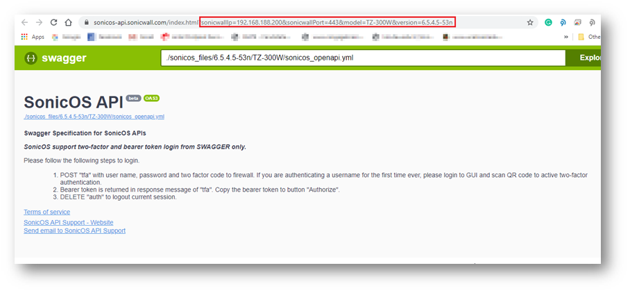
LIST OF APPLICABLE APIS:Navigate to MANAGE | API and click on the link https://SonicOS-api.sonicwall.com. Swagger will prepopulate your SonicWalls’s IP, MGMT Port, and Firmware so it can give you a list of applicable APIs.
LOGIN TO THE FIREWALL USING POSTMANThe following 3 steps need to be performed for every API request in Gen7 devices.
NOTE: https://IP-address:port/– Replace this with your SonicWall’s Public or private IP address with the right management port number (If the management port is 443, you can directly use https:// followed by the IP address without the port number too).
a) The HTTP method should be POST and we need to use the URL: https://192.168.168.168/api/sonicos/auth Under the authorization tab, select Basic Auth and mention the correct admin credentials.
b) Under the settings tab, turn OFF the Enable SSL certificate verification if the firewall uses a self-signed certificate for management.
c) Under the headers tab, include application/Json as the value for keys Accept and Content-type.
d) The Gen 7 devices are token-driven. Use the {“override” : true} under the body to override any older tokens. This is used only during login. After this, click on the Send button and then you can see the response in the section below. The response should contain a message: “success”.
e) After this, click on the Send button and then you can see the response in the section below. The response should contain a message: “success”.
cURL code: curl --location --request POST 'https://192.168.168.168/api/sonicos/auth' \--header 'Accept: application/Json' \--header 'Content-Type: application/Json' \--header 'Authorization: Basic YWRtaW46cGFzc3dvcmQ= --data-raw '{"override" : true}' Command Output should contain a string: “success”: true
Restart command Restart can be pushed in 2 ways: now or later. There is nothing in the body of the API call as you will notice in the screenshot below.
Restart in ___ minutes/hours/days/ If the plan is to restart after some time, you can schedule that. Please ensure you log out after the command since there is a waiting period. You can make other configurational changes, but it should be noted that you ‘commit’ the changes as a restart can clear off the pending configuration if not saved.
You may change the URL to suit your requirement. The number that you use should be an unsigned integer (UINT32) with values ranging from 0 to 4,294,967,295. For example, it can be made ../restart/in/2/days ../restart/in/24/hours
This release includes significant user interface changes and many new features that are different from the SonicOS 6.2 and earlier firmware. The below resolution is for customers using SonicOS 6.5 firmware.
Enabling the API Module on the firewall UI Login to the SonicWall management UI. Navigate to MANAGE | Appliance | Base Settings and scroll down to SonicOS API section. Enable the option ‘Enable SonicOS API’ and ‘Enable RFC-2617 HTTP Basic Access authentication’ options.
List of applicable APIs Navigate to MANAGE | API and click on the link https://SonicOS-api.sonicwall.com. Swagger will prepopulate your SonicWalls’s IP, MGMT Port, Firmware so it can give you a list of applicable APIs. TIP: You are free to choose Swagger, Postman, Git bash, or any application that allows API calls, if you are using a Linux based operating system you can execute cURL from the terminal. For this article I am using Git bash on Windows.
LOGIN TO THE FIREWALL USING POSTMANThe following 3 steps need to be performed for every API request in Gen7 devices.
NOTE: https://IP-address:port/– Replace this with your SonicWall’s Public or private IP address with the right management port number (If the management port is 443, you can directly use https:// followed by the IP address without the port number too).
a) The HTTP method should be POST and we need to use the URL: https://192.168.168.168/api/sonicos/auth Under the authorization tab, select Basic Auth and mention the correct admin credentials.
b) Under the settings tab, turn OFF the Enable SSL certificate verification if the firewall is using a self-signed certificate for management.
c) Under the headers tab, include application/Json as the value for keys Accept and Content-type.
d) The Gen 7 devices are token-driven. Use the {“override” : true} under the body to override any older tokens. This is used only during login. After this, click on the Send button and then you can see the response in the section below. The response should contain a message: “success”.
e) After this, click on the Send button and then you can see the response in the section below. The response should contain a message: “success”.
cURL code: curl --location --request POST 'https://192.168.168.168/api/sonicos/auth' \--header 'Accept: application/Json' \--header 'Content-Type: application/Json' \--header 'Authorization: Basic YWRtaW46cGFzc3dvcmQ= --data-raw '{"override" : true}' Command Output should contain a string: “success”: true
Restart command Restart can be pushed in 2 ways: now or later. There is nothing in the body of the API call as you will notice in the screenshot below.
Restart in ___ minutes/hours/days/ If the plan is to restart after some time, you can schedule that. Please ensure you log out after the command, if there is a waiting period. You can make other configurational changes, but it should be noted that you ‘commit’ the changes as a restart can clear off the pending configuration if not saved.
You may change the URL to suit your requirement. The number that you use should be an unsigned integer (UINT32) with values ranging from 0 to 4,294,967,295. For example, it can be made ../restart/in/2/days ../restart/in/24/hours
If you want to improve your network security and performance, learning how to set up a VLAN properly is all you need. Virtual LANs are powerful networking tools that allow you to segment your network into logical groups and isolate traffic between them.
In this post, we will go through the steps required to set up a VLAN in your network. We will configure two switches along with their interfaces and VLANs, respectively.
So, let’s dive in and learn how to set up VLANs and take your network to the next level.
Table of Contents
What is a VLAN?
Preparing for VLAN configuration
Our Lab
Network Diagram
How to set up a VLAN on a Switch?
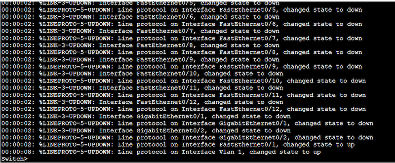
Let’s connect to the Switch
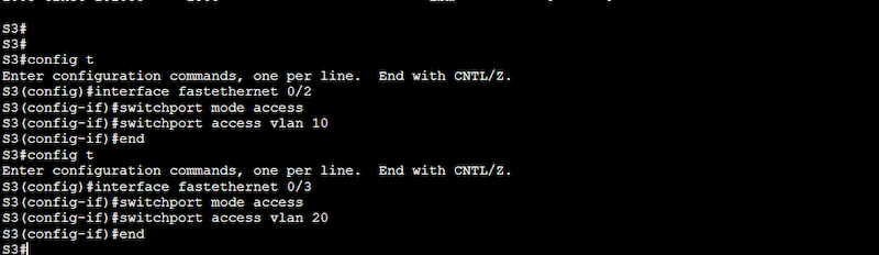
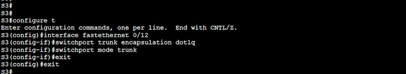
Configure VLANs
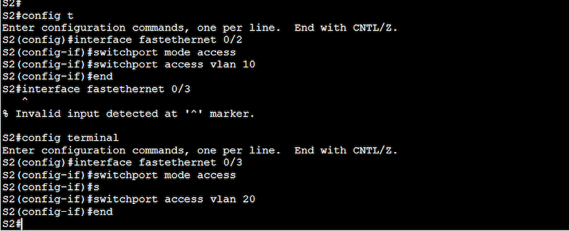
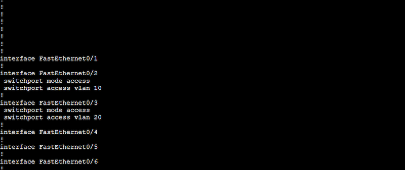
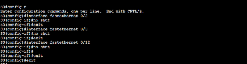
Assign switch ports to VLANs
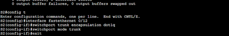
Configure trunk ports
Extra Configuration to Consider
What is a VLAN?
Before we go deep into learning how to set up a VLAN and provide examples, let’s understand the foundations of VLANs (or Virtual Local Area Networks).
In a nutshell, VLANs are logical groupings of devices that rely on Layer 2 addresses (MAC) for communication. VLANs are implemented to segment a physical network (or large Layer two broadcast domains) into multiple smaller logical networks (isolated broadcast domains).
Each VLAN behaves as a separate network with its own broadcast domain. VLANs help prevent broadcast storms (extreme amounts of broadcast traffic). They also help control traffic and overall improve network security and performance.
Preparing for VLAN configuration
Although VLANs are usually left for Layer 2 switches, in reality, any device (including routers and L3 switches) with switching capabilities and support of VLAN configuration should be an excellent fit for VLANs. In addition, VLANs are supported by different vendors, and since each vendor has a different OS and code, the way the VLANs are configured may slightly change.
Furthermore, you can also use specific software such as network diagramming and simulation to help you create network diagrams and test your configuration.
Our Lab
We will configure a popular Cisco (IOS-based) switch for demonstration purposes. We will use Boson NetSim (a network simulator for Cisco networking hardware and software) to run Cisco IOS simulated commands. This simulation is like you were configuring an actual Cisco switch or router.
Network Diagram
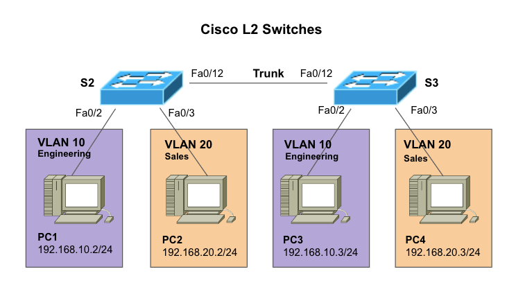
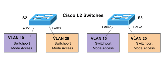
To further illustrate how to set up a VLAN, we will work on the following network diagram. We will configure two VLANs in two different switches. We will then configure each port on the switches connected to a PC. We will then proceed to configure the trunk port, which is vital for VLAN traffic.
Network diagram details
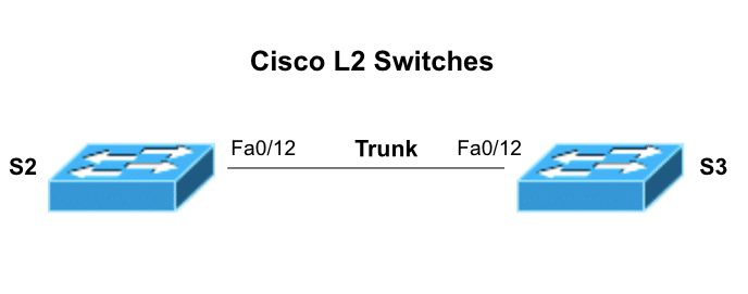
S2 and S3 (Switch 2 and Switch 3) – Two Cisco L2 Switches connecting PCs at different VLANs (VLAN 10 and VLAN 20) via Fast Ethernet interfaces.
VLANs 10 and VLAN20. These VLANs configured in L2 switches (S2 and S3) create a logical grouping of PCs within the network. In addition, each VLAN gets a name, VLAN 10 (Engineering) and VLAN 20 (Sales).
PCs. PC1, PC2, PC3, and PC4 are each connected to a specific L2 switch.
How to set up a VLAN on a Switch?
So now that you know the VLAN configuration we will be using, including the number of switches, VLAN ID, VLAN name, and the devices or ports that will be part of the configuration, let’s start setting up the VLANs.
Note:VLAN configuration is just a piece of the puzzle. Switches also need proper interface configuration, authentication, access, etc. To learn how to correctly connect and configure everything else, follow the step-by-step guide on how to configure a Cisco Switch.
a. Let’s connect to the switch
Inspect your hardware and find the console port. This port is usually located on the back of your Cisco switch. You can connect to the switch’s “console port” using a console cable (or rollover). Connect one end of the console cable to the switch’s console port and the other to your computer’s serial port.
Note: Obviously, not all modern computers have serial ports. Some modern switches come with a Mini USB port or AUX port to help with this. But if your hardware doesn’t have these ports, you can also connect to the switch port using special cables like an RJ-45 rollover cable, a Serial DB9-to-RJ-45 console cable, or a serial-to-USB adapter.
Depending on your switch’s model, you can configure it via Command Line Interface (CLI) or Graphical User Interface (GUI). We will connect to the most popular user interface: The IOS-based CLI.
To connect to your switch’s IOS-based CLI, you must use a terminal emulator on your computer, such as PuTTY or SecureCRT.
You’ll need to configure the terminal emulator to use the correct serial port and set the baud rate to 9600. Learn how to properly set these parameters in the Cisco switching configuration guide.
In the terminal emulator, press Enter to activate the console session. The Cisco switch should display a prompt asking for a username and password.
Enter your username and password to log in to the switch.
b. Configure VLANs
According to our previously shown network diagram, we will need two VLANs; VLAN 10 and VLAN 20.
To configure Layer 2 switches, you need to enter the privileged EXEC mode by typing “enable” and entering the password (if necessary).
Enter the configuration mode by typing “configure terminal.”
Create the VLAN with “vlan <vlan ID>” (e.g., “vlan 10”).
Name the VLAN by typing “name <vlan name>” (e.g., “name Sales”).
Repeat these two steps for each VLAN you want to create.
Configuration on Switch 2 (S2)
S2# configure terminal
S2(config)# vlan 10
S2(config-vlan)# name Engineering
S2(config-vlan)# end
S2# configure terminal
S2(config)# vlan 20
S2(config-vlan)# name Sales
S2(config-vlan)# end
Use the “show vlan” command to see the configured VLANs. From the output below, you’ll notice that the two new VLANs 10 (Engineering) and 20 (Sales) are indeed configured and active but not yet assigned to any port.
Configuration on Switch 3 (S3)
S3# configure terminal
S3(config)# vlan 10
S3(config-vlan)# name Engineering
S3(config-vlan)# end
S3# configure terminal
S3(config)# vlan 20
S3(config-vlan)# name Sales
S3(config-vlan)# end
Note: From the output above, you might have noticed VLAN 1 (default), which is currently active and is assigned to all the ports in the switch. This VLAN, also known as native VLAN, is the default VLAN on most Cisco switches. It is used for untagged traffic on a trunk port. This means that all traffic that is not explicitly tagged with VLAN information will be sent to this default VLAN.
Now, let’s remove those VLAN 1 tags from interfaces Fa0/2 and Fa0/3. Or in simple words let’s assign the ports to our newly created VLANs.
c. Assign switch ports to VLANs
In the previous section, we created our VLANs; now, we must assign the appropriate switch ports to the correct VLANs. The proper steps to assign switch ports to VLANs are as follows:
Enter configuration mode. Remember to run these commands under the configuration mode (configure terminal).
Assign ports to the VLANs by typing “interface <interface ID>” (e.g., “interface GigabitEthernet0/1”).
Configure the port as an access port by typing “switchport mode access”
Assign the port to a VLAN by typing “switchport access vlan <vlan ID>” (e.g., “switchport access vlan 10”).
Repeat these steps for each port you want to assign to a VLAN.
Let’s refer to a section of our network diagram
Configuration on Switch 2 (S2)
S2(config)# interface fastethernet 0/2
S2(config-if)# switchport mode access
S2(config-if)# switchport access vlan 10
S2(config)# interface fastethernet 0/3
S2(config-if)# switchport mode access
S2(config-if)# switchport access vlan 20
Use the “show running-configuration” to see the new configuration taking effect on the interfaces.
Configuration on Switch 3 (S3)
S3(config)# interface fastethernet 0/2
S3(config-if)# switchport mode access
S3(config-if)# switchport access vlan 10
S3(config)# interface fastethernet 0/3
S3(config-if)# switchport mode access
S3(config-if)# switchport access vlan 20
A “show running-configuration” can show you our configuration results.
d. Configure trunk ports
Trunk ports are a type of switch port mode (just like access) that perform essential tasks like carrying traffic for multiple VLANs between switches, tagging VLAN traffic, supporting VLAN management, increasing bandwidth efficiency, and allowing inter-VLAN routing.
If we didn’t configure trunk ports between our switches, the PCs couldn’t talk to each other on different switches, even if they were on the same VLAN.
Here’s a step by step to configuring trunk ports
Configure a trunk port to carry traffic between VLANs by typing “interface <interface ID>” (e.g., “interface FastEthernet0/12”).
Set the trunk encapsulation method (dot1q). The IEEE 802.1Q (dot1q) trunk encapsulation method is the standard tagging Ethernet frames with VLAN information.
Configure the port as a trunk port by typing “switchport mode trunk”.
Repeat the steps for each trunk port you want to configure.
Note (on redundant trunk links): To keep our article simple, we will configure one trunk link. However, keep in mind that any good network design (including trunk links) would need redundancy. One trunk link between switches is not an optimal redundant solution for networks on production. To add redundancy, we recommend using EtherChannel to bundle physical links together and configure the logical link as a trunk port. You can also use Spanning Tree Protocol (STP) by using the “spanning-tree portfast trunk” command.
Note: You can use different types of trunk encapsulation such as dot1q and ISL, just make sure both ends match the type of encapsulation.
Extra Configuration to Consider
Once you finish with VLAN and trunk configuration, remember to test VLAN connectivity between PCs, you can do this by configuring the proper IP addressing and doing a simple ping. Below are other key configurations related to your new VLANs that you might want to consider.
a. Ensure all your interfaces are up and running
To ensure that your interfaces are not administratively down, issue a “no shutdown” (or ‘no shut’) command on all those newly configured interfaces. Additionally, you can also use the “show interfaces” to see the status of all the interfaces.
b. (Optional) enable inter-VLAN
VLANs, as discussed earlier, separate broadcast domains (Layer 2) — they do not know how to route IP traffic because Layer 2 devices like switches can’t accept IP address configuration on their interfaces. To allow inter-VLAN communication (PCs on one VLAN communicate with PCs on another VLAN), you would need to use a Layer 3 device (a router or L3 switch) to route traffic.
There are three ways to implement inter-VLAN routing: an L3 router with multiple Ethernet interfaces, an L3 router with one router interface using subinterfaces (known as Router-On-a-Stick), and an L3 switch with SVI.
We will show a step-by-step on how to configure Router-On-a-Stick for inter-VLAN communications.
Connect the router to one switch via a trunk port.
Configure subinterfaces on the router for each VLAN (10 and 20 in our example). To configure subinterfaces, use the “interface” command followed by the VLAN number with a period and a subinterface number (e.g., “interface FastEthernet0/0.10” for VLAN 10). For example, to configure subinterfaces for VLANs 10 and 20, you would use the following commands:
> router(config-subif)# ip address 192.168.20.1 255.255.255.0
Configure a default route on the router using the “ip route” command. This is a default route to the Internet through a gateway at IP address 192.168.1.1. For example:
> router(config)# ip route 0.0.0.0 0.0.0.0 192.168.1.1
c. Configure DHCP Server
To automatically assign IP addresses to devices inside the VLANs, you will need to configure a DHCP server. Follow these steps:
The DHCP server should also be connected to the VLAN.
Configure the DHCP server to provide IP addresses to devices in the VLAN.
Configure the router to forward DHCP requests to the DHCP server by typing “ip helper-address <ip address>” (e.g., “ip helper-address 192.168.10.2”).
Final Words
By following the steps outlined in this post, you can easily set up a VLAN on your switch and effectively segment your network. Keep in mind to thoroughly test your VLAN configuration and consider additional configuration options to optimize your network for your specific needs.
With proper setup and configuration, VLANs can greatly enhance your network’s capabilities and 10x increase its performance and security.
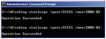
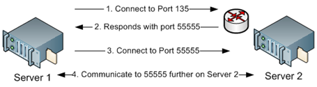
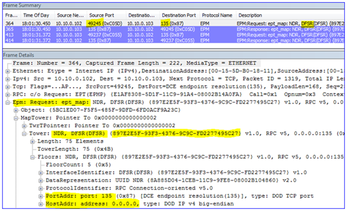
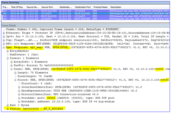
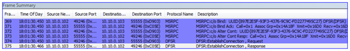

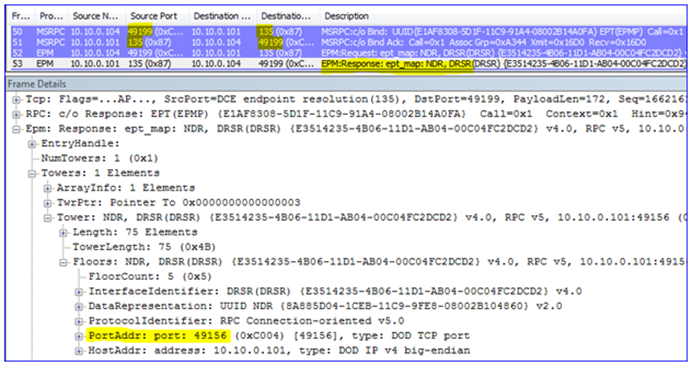
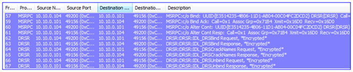
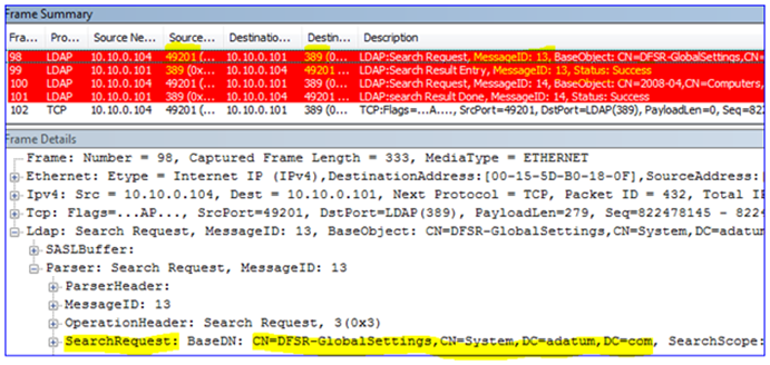
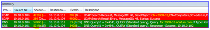
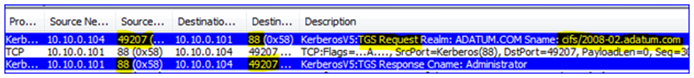
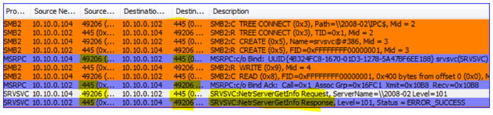
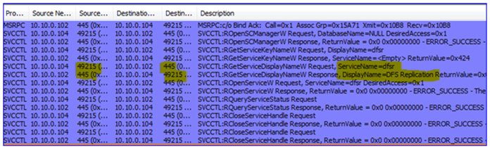
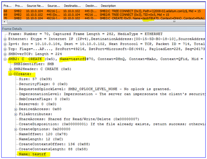
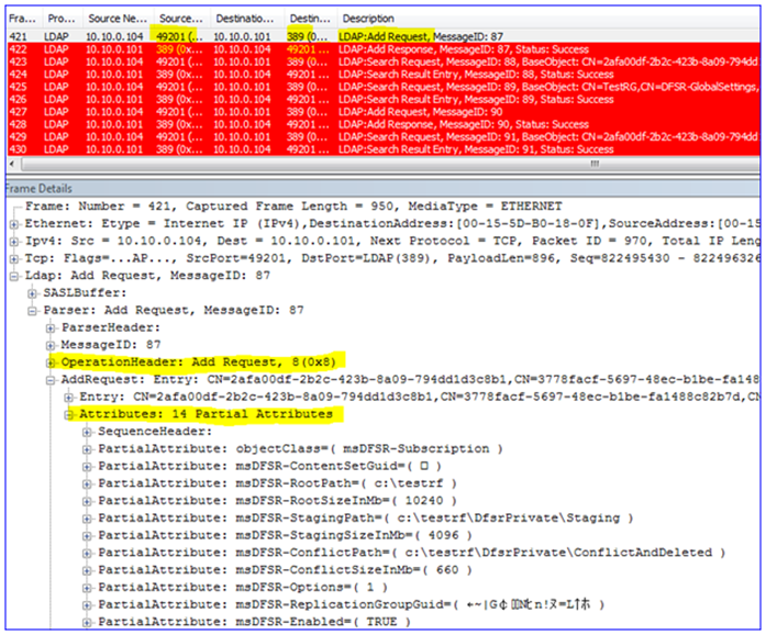
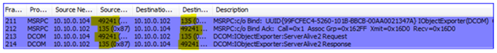
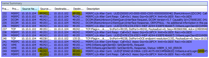
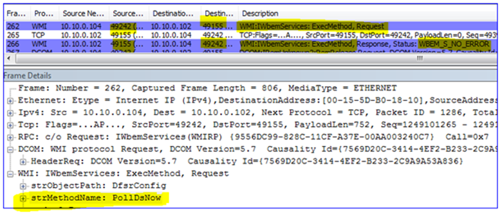
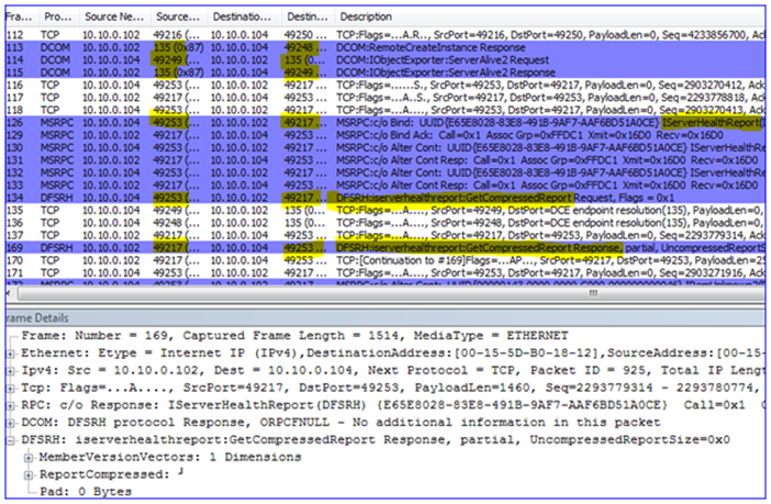


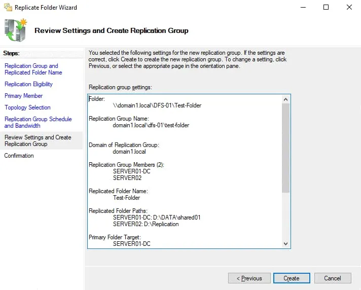


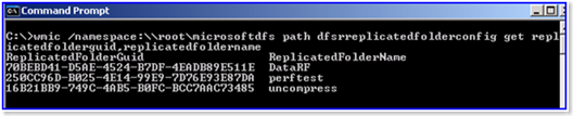
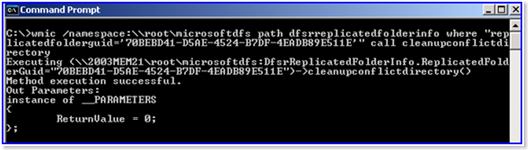
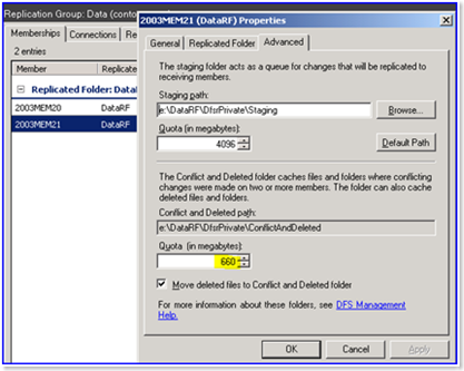
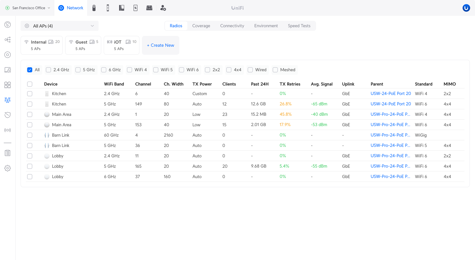
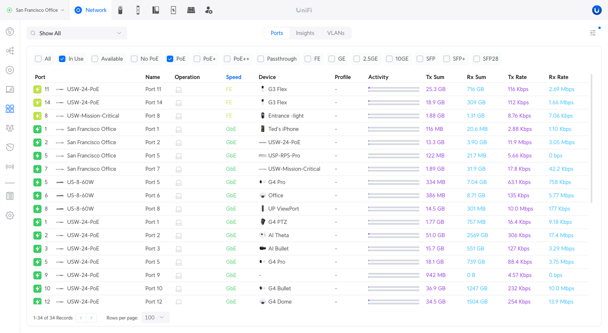
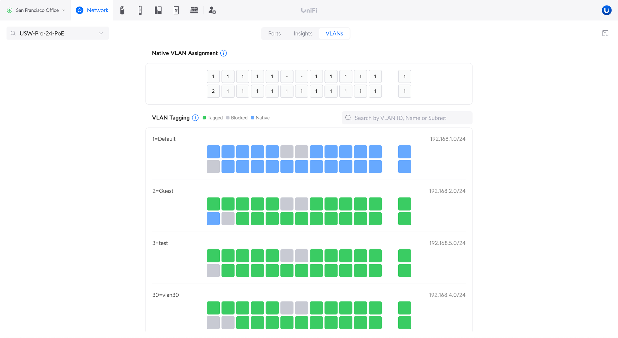
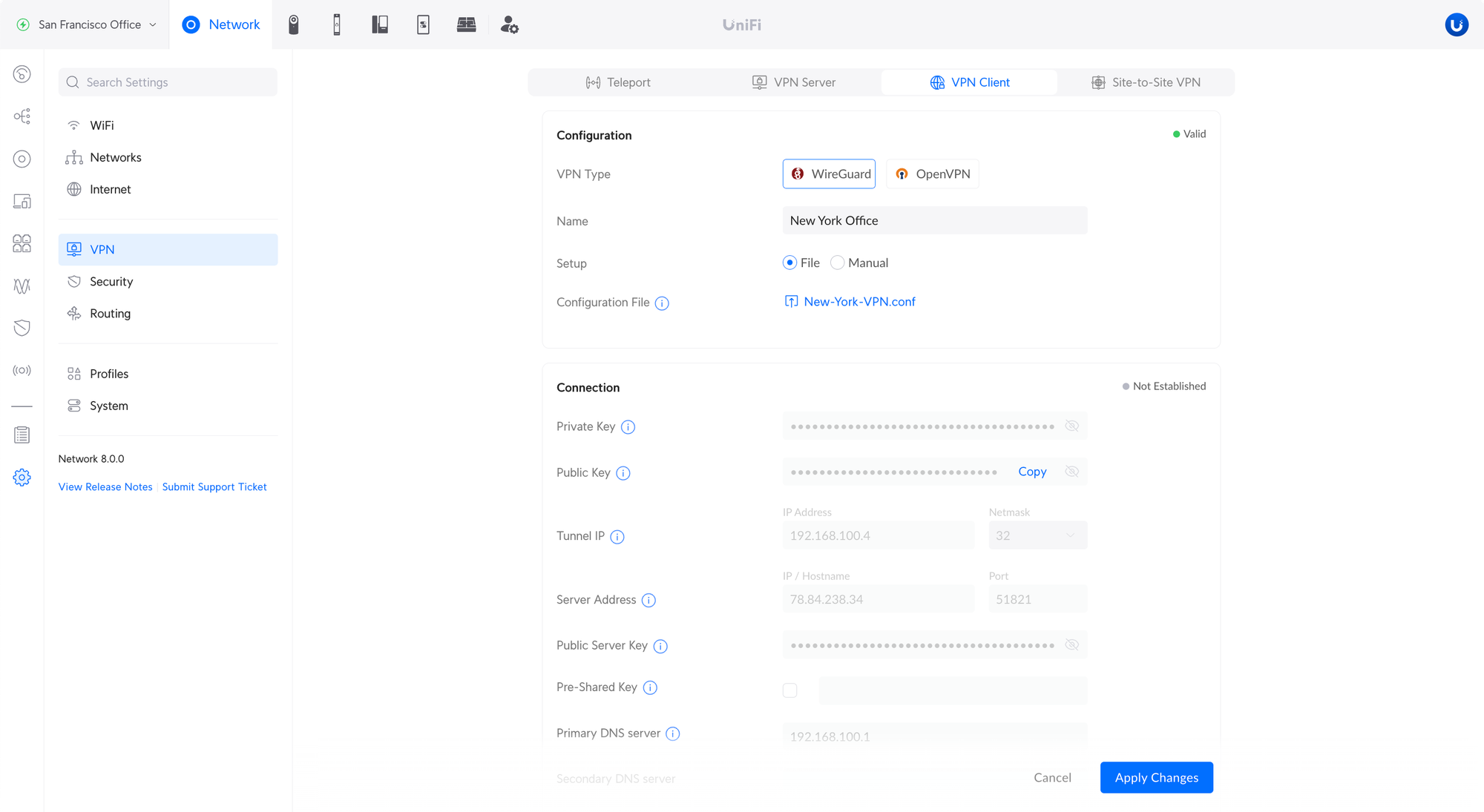
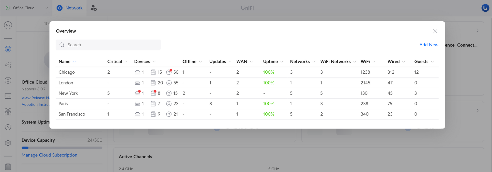

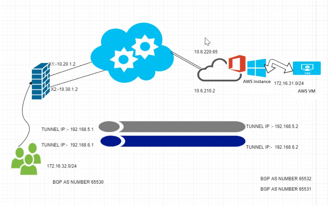
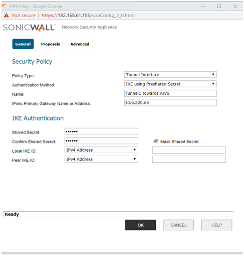
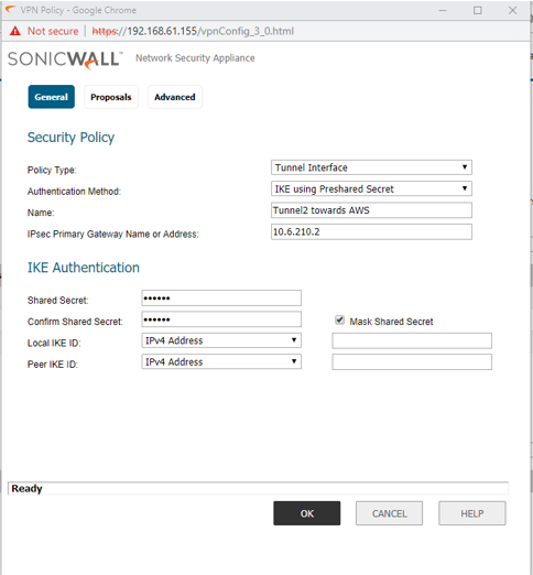
 NOTE: The Proposals tab must be identical on the Tunnel Interface VPNs for both appliances and should Bind with X1 and X2.
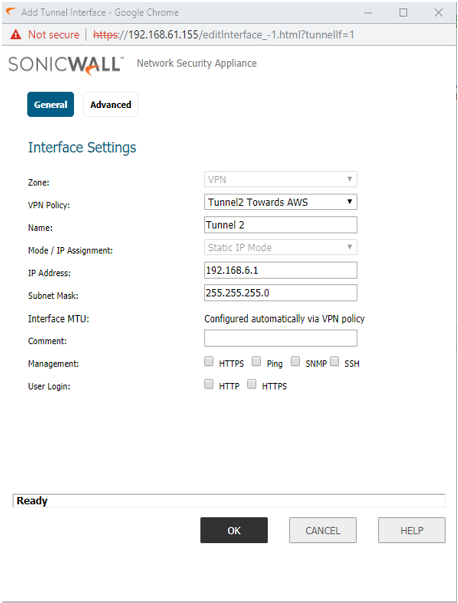
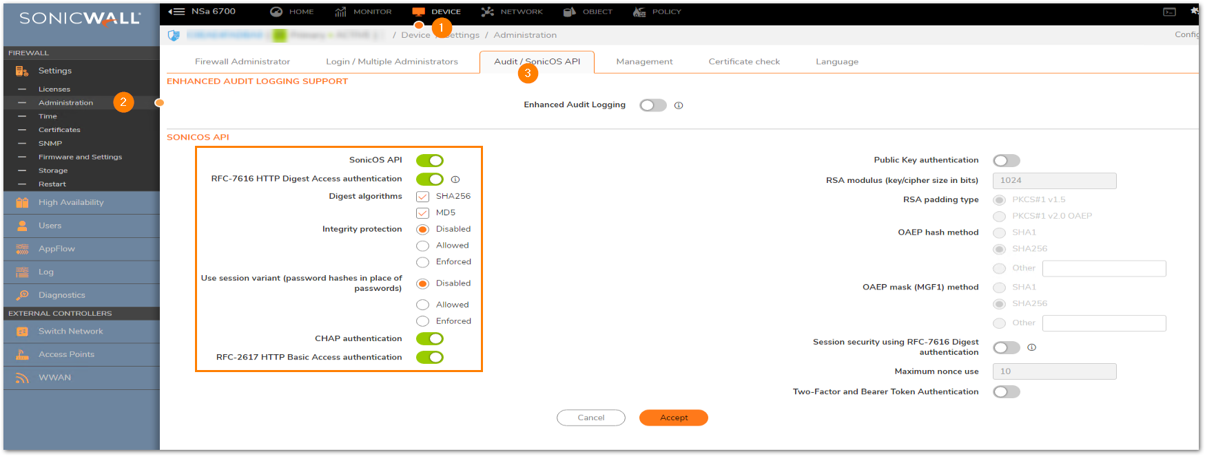
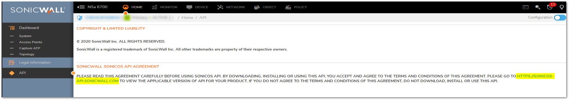
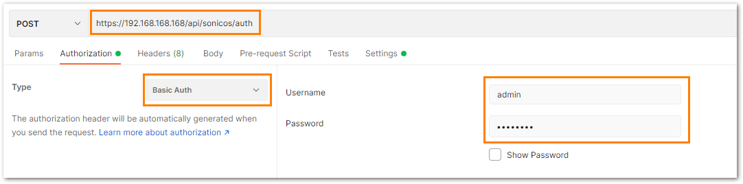
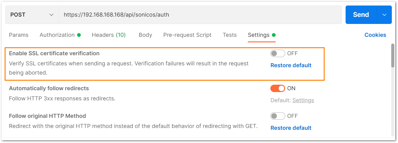
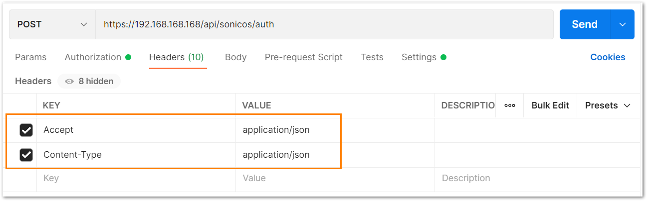
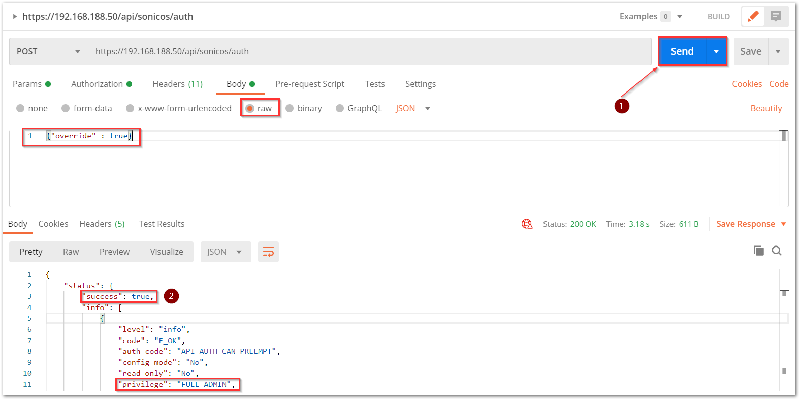
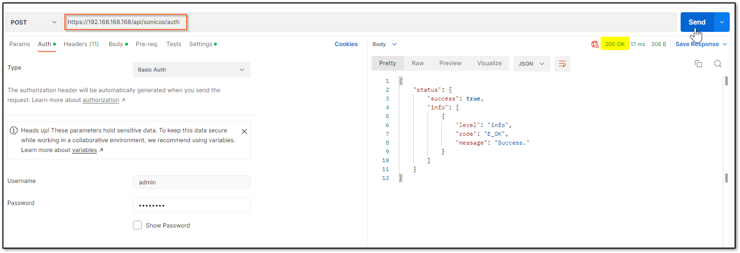
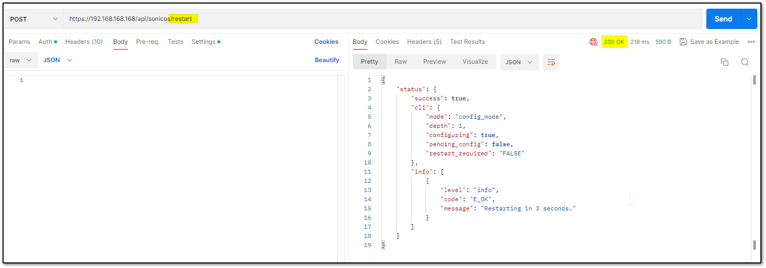
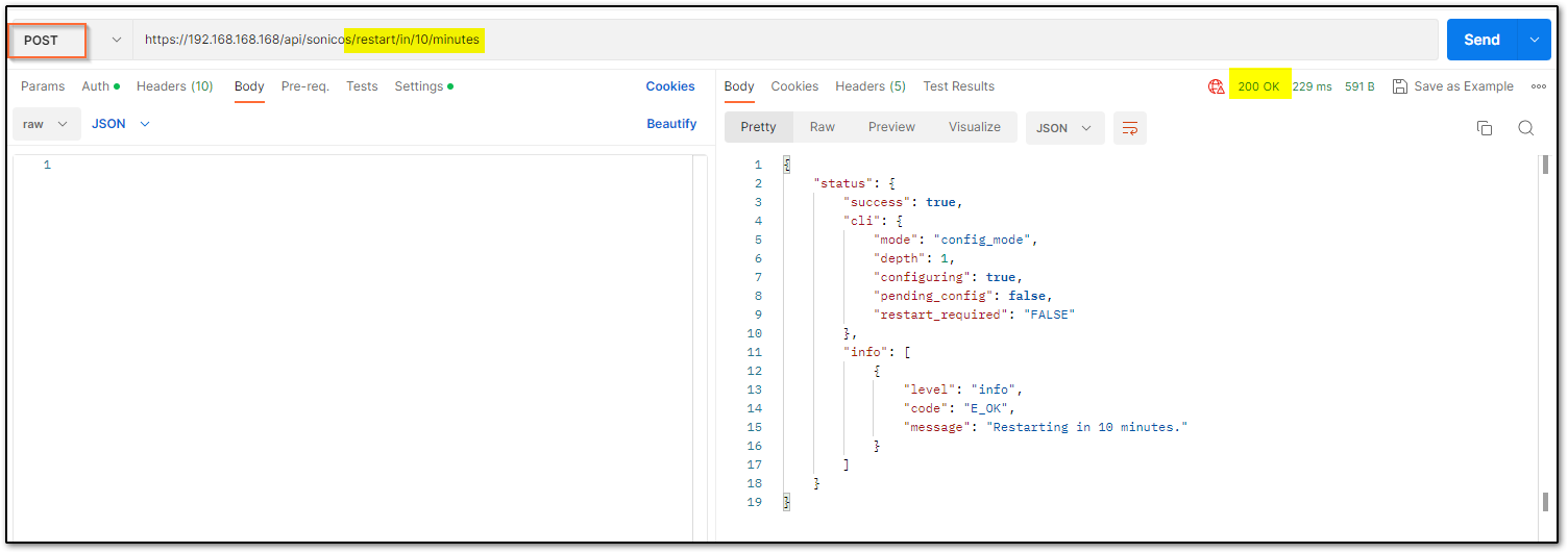
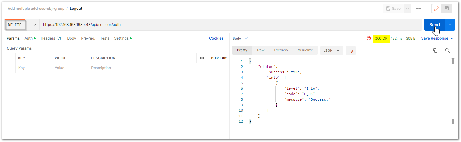
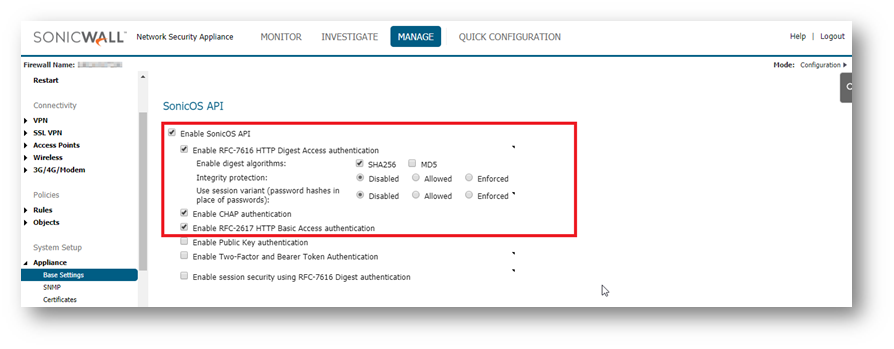
 TIP: You are free to choose Swagger, Postman, Git bash, or any application that allows API calls, if you are using a Linux based operating system you can execute cURL from the terminal. For this article I am using Git bash on Windows.