In H1 2022, malicious objects were blocked at least once on 31.8% of ICS computers globally.Percentage of ICS computers on which malicious objects were blocked
For the first time in five years of observations, the lowest percentage in the first half of the year was observed in March. During the period from January to March, the percentage of attacked ICS computers decreased by 1.7 p.p.Percentage of ICS computers on which malicious objects were blocked, January – June 2020, 2021, and 2022
Among regions, the highest percentage of ICS computers on which malicious objects were blocked was observed in Africa (41.5%). The lowest percentage (12.8%) was recorded in Northern Europe.Percentage of ICS computers on which malicious objects were blocked, in global regions
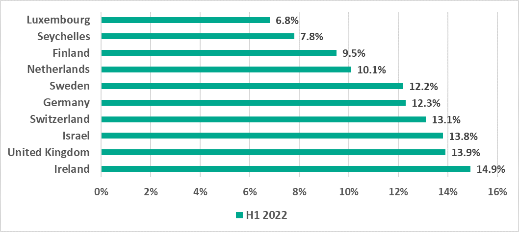
Among countries, the highest percentage of ICS computers on which malicious objects were blocked was recorded in Ethiopia (54.8%) and the lowest (6.8%) in Luxembourg.15 countries and territories with the highest percentage of ICS computers on which malicious objects were blocked, H1 202210 countries and territories with the lowest percentage of ICS computers on which malicious objects were blocked, H1 2022
Threat sources
The main sources of threats to computers in the operational technology infrastructure of organizations are internet (16.5%), removable media (3.5%), and email (7.0%).Percentage of ICS computers on which malicious objects from different sources were blocked
Regions
Among global regions, Africa ranked highest based on the percentage of ICS computers on which malware was blocked when removable media was connected.Regions ranked by percentage of ICS computers on which malware was blocked when removable media was connected, H1 2022
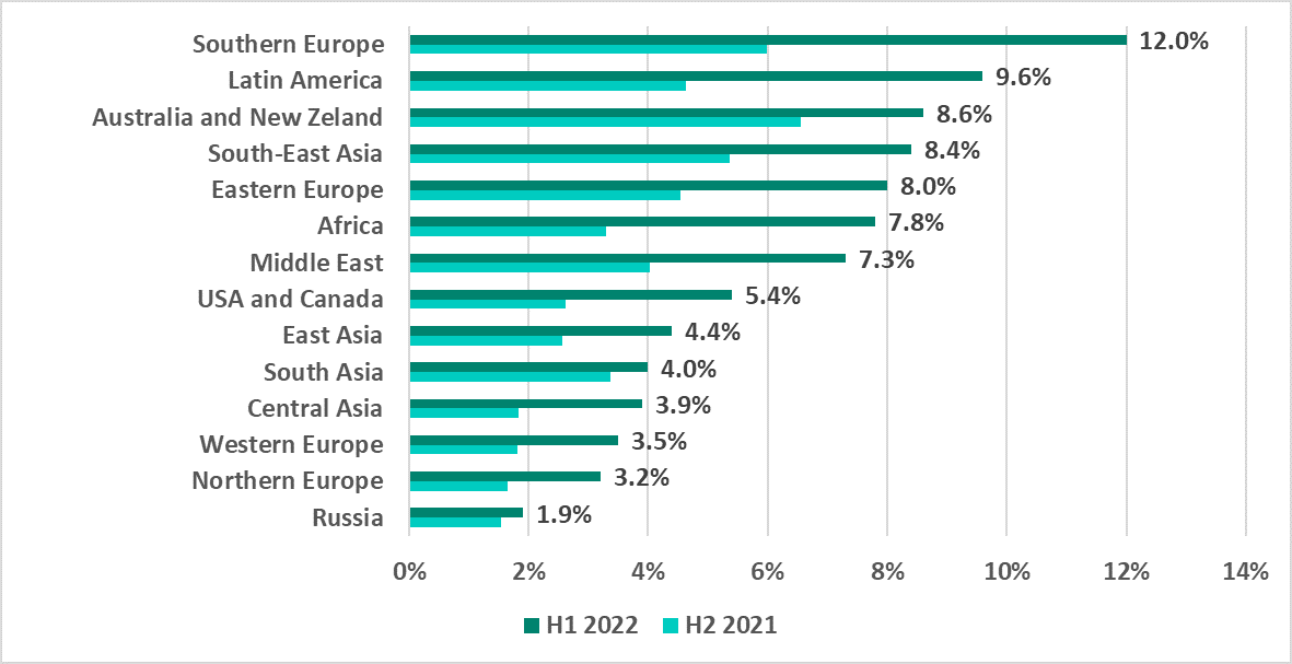
Southern Europe leads the ranking of regions by percentage of ICS computers on which malicious email attachments and phishing links were blocked.Regions ranked by percentage of ICS computers on which malicious email attachments and phishing links were blocked, H1 2022
Industry specifics
In the Building Automation industry, the percentage of ICS computers on which malicious email attachments and phishing links were blocked (14.4%) was twice the average value for the entire world (7%).Percentage of ICS computers on which malicious email attachments and phishing links were blocked, in selected industries
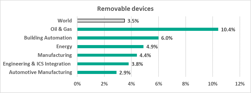
In the Oil and Gas industry, the percentage of ICS computers on which threats were blocked when removable media was connected (10.4%) was 3 times the average percentage for the entire world (3.5%).Percentage of ICS computers on which threats were blocked when removable media was connected
In the Oil and Gas industry, the percentage of ICS computers on which malware was blocked in network folders (1.2%) was twice the world average (0.6%).Percentage of ICS computers on which threats were blocked in network folders
Diversity of malware
Malware of different types from 7,219 families was blocked on ICS computers in H1 2022.Percentage of ICS computers on which the activity of malicious objects from different categories was prevented
Ransomware
In H1 2022, ransomware was blocked on 0.65% of ICS computers. This is the highest percentage for any six-month reporting period since 2020.Percentage of ICS computers on which ransomware was blocked
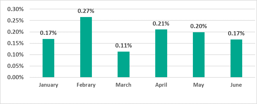
The highest percentage of ICS computers on which ransomware was blocked was recorded in February (0.27%) and the lowest in March (0.11%). The percentage observed in February was the highest in 2.5 years of observations.Percentage of ICS computers on which ransomware was blocked, January – June 2022
East Asia (0.95%) and the Middle East (0.89%) lead the ransomware-based ranking of regions. In the Middle East, the percentage of ICS computers on which ransomware was blocked per six-month reporting period has increased by a factor of 2.5 since 2020.Regions ranked by percentage of ICS computers on which ransomware was blocked, H1 2022
Building Automation leads the ranking of industries based on the percentage of ICS computers attacked by ransomware (1%).Percentage of ICS computers on which ransomware was blocked, in selected regions, H1 2022
Malicious documents
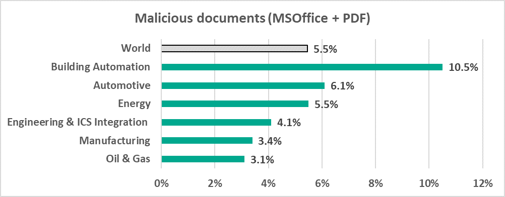
Malicious documents (MSOffice+PDF) were blocked on 5.5% of ICS computers. This is 2.2 times the percentage recorded in H2 2021. Threat actors distribute malicious documents via phishing emails and actively use such emails as the vector of initial computer infections.Percentage of ICS computers on which malicious documents (MSOffice+PDF) were blocked
In the Building Automation industry, the percentage of ICS computers on which malicious office documents were blocked (10.5%) is almost twice the global average.Percentage of ICS computers on which malicious office documents (MSOffice+PDF) were blocked, in selected industries
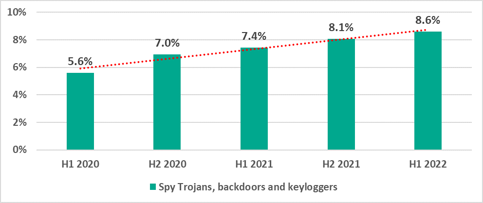
Spyware
Spyware was blocked on 6% of ICS computers. This percentage has been growing since 2020.Percentage of ICS computers on which spyware was blocked
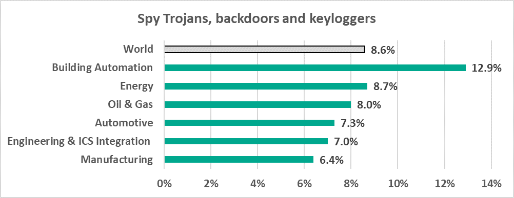
Building Automation leads the ranking of industries based on the percentage of ICS computers on which spyware was blocked (12.9%).Percentage of ICS computers on which spyware was blocked, in selected industries
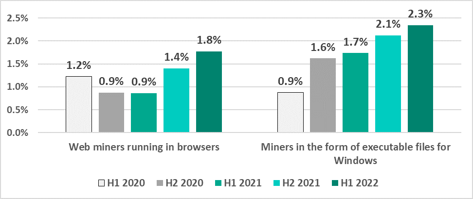
Malware for covert cryptocurrency mining
The percentage of ICS computers on which malicious cryptocurrency miners were blocked continued to rise gradually.Percentage of ICS computers on which malicious cryptocurrency miners were blocked
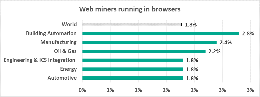
Building Automation also leads the ranking of selected industries by percentage of ICS computers on which malicious cryptocurrency miners were blocked.Percentage of ICS computers on which malicious cryptocurrency miners were blocked, in selected industries
A critical remote code-execution vulnerability (CVE-2021-44228) has been publicly disclosed in Log4j, an open-source logging utility that’s used widely in applications, including many utilized by large enterprise organizations.
The vulnerability allows threat actors to exfiltrate information from, and execute malicious code on, systems running applications that utilize the library by manipulating log messages. There already are reports of servers performing internet-wide scans in attempts to locate vulnerable servers, and our threat intelligence teams are seeing attempts to exploit this vulnerability at alarming volumes. Log4j is incorporated into many popular frameworks and many Java applications, making the impact widespread.
Akamai Guardicore Segmentation is well positioned to address this vulnerability in different ways. It’s highly recommended that organizations update Log4j to its latest version- 2.16.0. Due to the rapidly escalating nature of this vulnerability, Akamai teams will continue to develop and deploy mitigation measures in order to support our customers.
As a follow up to Akamai’s recent post we wanted to provide more detail on how organizations can leverage Akamai Guardicore Segmentation features to help address log4j exposure.
Log4j vulnerability: scope and impact
Log4j is a Java-based open-source logging library. On December 9, 2021, a critical vulnerability involving unauthenticated remote code execution (CVE-2021-44228) in Log4j was reported, causing concern due to how commonly Log4j is used. In addition to being used directly in a large multitude of applications, Log4j is also incorporated into a host of popular frameworks, including Apache Struts2, Apache Solr, Apache Druid, and Apache Flink.
Although Akamai first observed exploit attempts on the Log4j vulnerability on December 9th, following the widespread publication of the incident, we are now seeing evidence suggesting it could have been around for months. Since widespread publication of the vulnerability, we have seen multiple variants seeking to exploit this vulnerability, at a sustained volume of attack traffic at around 2M exploit requests per hour. The speed at which the variants are evolving is unprecedented.
A compromised machine would allow a threat actor to remotely provide a set of commands which Log4j executes. An attacker would have the ability to run arbitrary commands inside a server. This can allow an attacker to compromise a vulnerable system – including those that might be secured deep inside of a network with no direct access to the internet.
Akamai’s security teams have been monitoring attackers attempting to use Log4j in recent days. Other than the increase in attempted exploitation, Akamai researchers are also seeing attackers using a multitude of tools and attack techniques to get vulnerable components to log malicious content, in order to get remote code execution. This is indicative of threat actors’ ability to exploit a new vulnerability, and the worse the vulnerability is, the quicker they will act.
Mitigating Log4j abuse using Akamai Guardicore Segmentation
Customers using Akamai Guardicore Segmentation can leverage its deep, process level visibility to identify vulnerable applications and potential security risks in the environment. They can then use it to enact precise control over network traffic in order to stop attempted attacks on vulnerable systems, without disruptions to normal business operations.
Guardicore Hunt customers have their environments monitored and investigated continuously by a dedicated team of security researchers. Alerts on security risks and suggested mitigation steps are immediately sent.
If you’d like to hear more about Akamai Guardicore Segmentation, read more or contact us.
What’s under threat: identify vulnerable Java processes and Log4j abuse
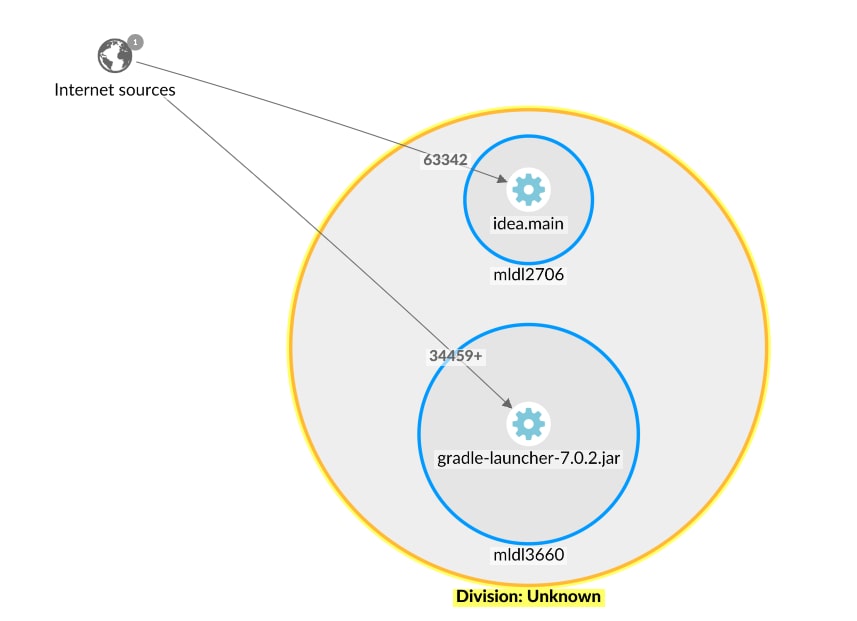
In order to protect against potential Log4j abuse, it is necessary to first identify potentially exploitable processes. This requires deep visibility into network traffic at the process level, which is provided by the Reveal and Insight features of Akamai Guardicore Segmentation. Precise visibility into internet connections and traffic at the process level allows us to see clearly what mitigation steps need to be taken, and visibility tools with historical data are pivotal in helping to prevent disruption to business operations.
Identify internet connected Java applications: using Reveal Explore Map, create a map for the previous week, and filter by java applications- such as tomcat, elastic, logstash- and by applications that have connections to/from the internet. Using this map, you can now see which assets are under potential threat. While this won’t yet identify Log4j applications, this can give you an idea of which machines to prioritize in your mitigation process.
Create a historical map to analyze normal communication patterns: using Reveal Explore Map, create a historical map of previous weeks (excluding the time since Log4j was reported) to view and learn normal communication patterns. Use this information to identify legitimate communications, and respond without disrupting the business. For example, a historical map might indicate what network connections exist under normal circumstances, those could be allowed, while other connections blocked or alerted on. Additionally, compare and contrast with a more recent map to identify anomalies.
Identify applications vulnerable to Log4j abuse: in the query section below, use Query 1 with Insight queries to identify assets that are running Java applications which have Log4j jar files in their directories. This query should return all Log4j packages in your environment, allowing you to assess and address any mitigation steps needed. To better prioritize exposed machines, cross reference the information with the Reveal Explore Map described previously.
Note that this query identifies Log4j packages that exist in the Java process current working directory or sub-directories.
Detect potential exploitation attempts in Linux logs: run an Insight query using YARA signature rule (Query 2, provided below in the query section) to search for known Log4j IoCs in the logs of linux machines. This can help you identify whether you’ve been attacked.
Note, a negative result does not necessarily mean that no attack exists, as this is only one of many indicators.
Stopping the attack: using Guardicore Segmentation to block malicious IoCs and attack vectors
It is imperative to be able to take action, once vulnerable applications have been identified. While patching is underway, Akamai Guardicore Segmentation offers a multitude of options for alerting on, stopping and preventing potential attacks. Critically, a solution with detailed and precise control over network communication and traffic is required to be able to surgically block or isolate attack vectors, with minimal to no disruption to normal business functions.
Automatically block IoC’s with Threat Intelligence Firewall (TIFW) and DNS Security: Akamai security teams are working around the clock to identify IPs and Domains used for Log4j exploitation. Customers who have these features turned on can expect a constantly updated list of IoCs to be blocked, preventing Log4j being used to download malicious payloads. Note that TIFW can be set to alert or block, please ensure it’s configured correctly. DNS Security is available from V41 onwards. The IoCs are also available on the Guardicore Threat Intel Repository and Guardicore Reputation Service.
Fully quarantine compromised servers: if compromised machines are identified during your investigation, use Akamai Guardicore Segmentation to isolate attacked/vulnerable servers from the rest of your network. Leverage built-in templates to easily enable deployment of segmentation policy to mitigate attacks.
Block inbound and outbound traffic to vulnerable assets: as a precautionary measure, you may also choose to block traffic to all machines identified with an unpatched version of Log4j, until patching is completed. Using a historical map of network traffic can help you limit the impact on business operations.
Create block rules for outgoing traffic from Java applications to the internet: if necessary, all internet-connected Java applications revealed in previous steps can be blocked from accessing the internet, as an additional precaution, until patching is complete.
Search queries
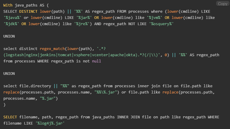
Query 1: To Identify assets that are running Java applications, which also have a Log4j jar file under their directories, run the following Insight query:
Query 2: To detect potential exploitation attempts, run an Insight query using YARA signature rules (our thanks to Florian Roth who published the original rule):
SELECT path, count FROM yara WHERE path LIKE '/var/log/%%' AND sigrule = "rule EXPL_Log4j_CallBackDomain_IOCs_Dec21_1 {
$sa1 = {22 2E 6C 6F 67 34 6A 2E 63 6F 72 65 2E 6E 65 74 2E 4A 6E 64 69 4D 61 6E 61 67 65 72 2E 6C 6F 6F 6B 75 70 28 4A 6E 64 69 4D 61 6E 61 67 65 72 22}
To satisfy the increasing demand for embedded network surveillance solutions on NAS, QNAP unveiled a value-added application ‘Surveillance Station’ on its All-in-One Turbo NAS Series. The Surveillance Station enables users to configure and connect many IP cameras at the same time and manage functions including live audio & video monitoring, recording, and playback. Installation and configuration can be easily carried out remotely in a web browser in a few steps. Various recording modes are provided: continuous recording, motion-detection recording, and scheduled recording. Users can flexibly define the recording settings according their security plans. The Surveillance Station supports a large number of IP camera brands. You can find a list of supported cameras at: https://www.qnap.com/compatibility.
Contents
Plan your home/office network topology
Set up the IP Cameras
Configure the Surveillance Station on the QNAP NAS
Configure Alarm Recording on the QNAP NAS
Play Video Files from the Surveillance Station
Plan Your Home/Office Network Topology
Write down your plan of the home/office network before starting to set up the surveillance system. Consider the following when doing so:
The IP address of the NAS
The IP address of the cameras
The IP address of your router and the wireless SSID
Your computer, the NAS, and the IP cameras should be installed to the same router in LAN. Assign fixed IP addresses for the NAS and the IP cameras. For example:
The LAN IP of the router: 192.168.1.100
Camera 1 IP: 192.168.1.10 (fixed IP)
Camera 2 IP: 192.168.1.20 (fixed IP)
NAS IP: 192.168.1.60 (fixed IP)
Set up the IP Cameras
Configure the IP address for both IP cameras using the following steps. You can download a camera IP Finder from official website of your camera’s vendor. The name of the IP finder may differ between vendors. IP Finder is a utility that helps you search for the IP address of the camera. CONNECT the IP camera to your home/office network with a network cable and run the IP Finder. Set the IP address of the cameras so that they are on the same LAN as the computer. You will then be able to login to the configuration page of the camera with a web browser. Enter the IP address of the first camera as 192.168.1.10. The default gateway should be set as the LAN IP of the router (192.168.1.100 in our example).
Note: The default IP and ID of administrator may differ based on what camera model is used.
ENTER the web configuration page of the IP camera. You will then be able to view the monitoring image.
GO to ‘Network/ Network’ and check the IP settings of the camera.
NEXT, if you are using a Wireless IP CAM, please go to “Network/Wireless” and configure the wireless setting of your camera. Please ensure the camera’s settings are completed.
Repeat the above steps to set up the second camera. To summarize, so far you have finished the following settings:
Camera 1 IP: 192.168.1.10
Camera 2 IP: 192.168.1.20
Note: If you forget the camera settings, please press the reset button at the back of the camera for 5-10 seconds. The camera will be restored to default settings. You can then set the IP address and login to the camera’s configuration page with using the default login name and password. The reset function may differ by the brand of the camera. Please refer to the camera’s user manual in advance.
Configure the Surveillance Station on the QNAP NAS
Go to “Control Panel” > “System Settings” >”Network” > “TCP/IP” and press the “Edit” button to specify a fixed IP to the NAS: 192.168.1.60. The default gateway should be the same as the LAN IP of your router, which is 192.168.1.100 in our example.
Install Surveillance Station
Auto installation: Go to “App Center” > “Surveillance” > “Surveillance Station” and click “Add to QTS” to start installation.
Manual installation: Download the Surveillance Station QPKG from the App Center on the QNAP website. Then you can install it by clicking the “Install Manually” button and by selecting the location of the Surveillance Station QPKG to start installing.
Please note: To ensure proper operations of Surveillance Station, we recommend rebooting the Turbo NAS after its installation is completed.
In the Surveillance Station, please go to “Settings” and select “Camera 1” then click “” to add the camera configuration, e.g. name, model, IP address, recording setting and recording schedule.
In our demonstration we will assign the following IPs to each camera: Camera 1 IP: 192.168.1.10 Camera 2 IP: 192.168.1.20
Note: Before applying the settings, you may click “Test” on the right to ensure the connection to the IP camera is successful.
You can enable or change the recording option of the camera in next page. Click “next” to move to the next page.
On this page, you will see the “Schedule Settings.” In the table, 0~23 represents the time period. For example, 0 means 00:00~01:00, 1 means 01:00~02:00. You can set a continuous recording in any period that you want.
Then you will see the “Confirm Settings” on the next page.
After you have added the network cameras to the NAS, go to the “Monitor” page. The first time you access this page by browser, you have to install the ActiveX control (QMon.cab) in order to view the images of Camera 1 and Camera 2.
Note: You can use the Surveillance Station in Chrome, Firefox or IE. The browser will prompt you to install the “ActiveX control” (QMon.cab) before using Monitor or Playback functions. Please follow the on-screen instructions to complete the installation.
Note: When you click on the monitoring screen of a camera, the frame will become orange. You can use the s configuration page. In Surveillance Station 5, there is a new feature called “Instant Playback”. You can click the floating button to play recording and find recent event.
Configure Alarm Recording on the QNAP NAS
The Surveillance Station supports alarm recording by schedule. To use this function, go to “Camera Settings” > “Alarm Settings” in the Surveillance Station. You could select ‘Traditional Mode’ to do basic configurations or ‘Advanced Mode’ to define advanced alarm events.
Traditional Mode : You may define criteria enabling alarm recording then click ‘Apply’ to save the changes.
Advanced Mode : You may select the event on the left side and add an action on the right side by clicking “Add”.
Then you may choose the action type you need for this event.
The event “Motion Detection” has a corresponding action “Recording”.
Play Video Files from the Surveillance Station
You have to click or to enter the playback page and follow the steps below to play the video files on the remote Surveillance Station.
1. Drag and drop camera(s) from the server/camera tree to the respective playback window(s) to select the channel(s) for playback.
2. Select playback date from.You can examine each channel to know the time range when the files were recorded for each IP camera. The blue cells indicate regular recording files and the red cells indicate alarm recording files. If it is blank, it means no files are recorded at that time.
3. Clickto start the playback. You can control the speed and playback direction by dragging the button to right or left on the shuttle bar.
4. Specify the time to play back the recording files at that moment. You can view the preview image on the timeline bar to search the moment you want to play.
5. Clickto control all the playback windows to play back the recording files. When this function is enabled, the playback options (play, pause, stop, previous/next frame, previous/next file, speed adjustment) will be applied to all the playback windows.
The Recovery Mode User Interface (UI) is a special interface for UniFi OS Consoles (UDMP, UNVR, etc.) and gateways used to recover from various failure modes (indicated on the LCM screen of that device). From the Recovery Mode, you can perform the following actions:
Reset to Factory Defaults: Completely reset the device. Note this will also wipe out any stored backup files.
Reboot: Restart the device and re-load the existing configuration.
Power-off: Initiate a software shutdown on the device, after which you can safely remove the power cable.
Check Filesystems: Check the integrity of the file system.
Firmware Update: Upload a previously downloaded firmware image (.bin) file in order to upgrade the firmware.
You should only resort to using recovery mode if you are prompted by the LCM screen found on your device.
Performing a Device Recovery
Download the most recent firmware for your device. You can find information on our latest releases here.
Completely power-off the UniFi device and unplug it from its power source.
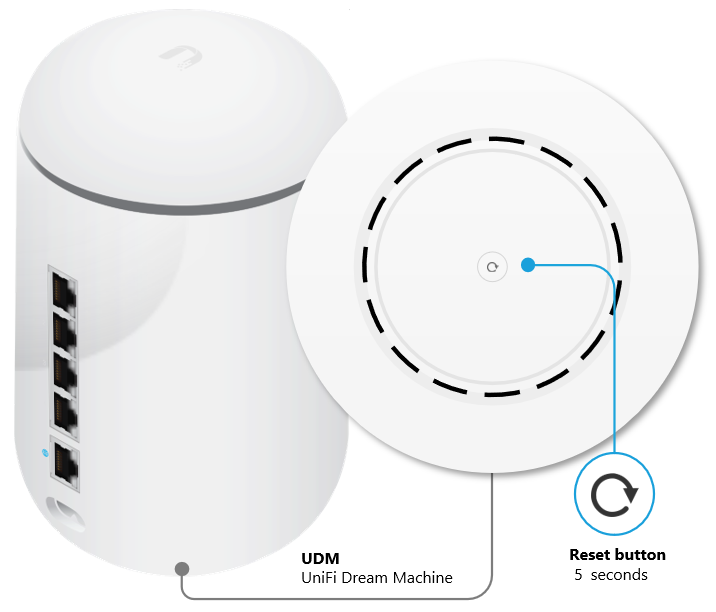
Press and hold the reset button and then power on the device by connecting it to the power source once again.
Keep the reset button pressed for about 5 seconds. After some time the display (in supported models) will indicate that the gateway is in Recovery Mode.
Connect an Ethernet cable from your computer to the first LAN port (port 1) on the UniFi gateway.
Note: Port 1 is always the first one. Either the top port, or the top left corner one, depending on the layout of your device’s ports.
Configure a static IP address on your computer in the 192.168.1.0/24 range (for example 192.168.1.11). Windows ClientmacOS clientNote: If a wireless adapter is enabled and connected to another network it could conflict with the connection to the UniFi device. Disable the wireless adapter if necessary.
Open a compatible web browser navigate to http://192.168.1.30 to access the Recovery Mode UI.
Note: The Recovery Mode UI is accessible via HTTP only and not HTTPS. It is possible that your browser will automatically try to redirect your session to HTTPS. Make sure to navigate to the http://192.168.1.30 address and use a different browser if necessary.
Select Firmware Update > Choose and browse your computer for the previously download firmware (.bin) image file.
Wait for the upgrade process to complete and reboot the device afterwards.
We do not recommend using SSH unless instructed by one of our Support Engineers as part of advanced troubleshooting. Inexperienced users risk making changes that may degrade network performance, or even worse, completely break your deployment. Proceed with caution.
Requirements
1. You are connected to the same local network as the device/console you plan to connect with via SSH. This may consist of using a laptop connected to the same WiFi network, or hardwired directly to the device.
2. SSH is enabled. UniFi Network devices and UniFi OS Consoles have independent SSH settings.
UniFi OS Consoles – Following setup, SSH is automatically disabled. It must be enabled in your UniFi OS System Settings.
UniFi Network Devices – Following setup, SSH is automatically enabled. The credentials consist of a random string of characters.
3. The device you are using has a command line interface (CLI) capable of establishing a Secure Shell (SSH) connection. Linux and macOS devices can use their native terminal. Windows OS requires PowerShell or PuTTY.
Establishing an SSH Connection
The format of the command used to establish an SSH connection is as follows:
ssh <username>@<ip-address>
The <username> for UniFi OS Consoles (UDM Pro / UNVR / Cloud Key) and UniFi Gateways (UXG Pro) is always ‘root’. For example, a Dream Machine Pro (gateway) with an IP address of 192.168.1.1 can be accessed as follows:
ssh root@192.168.1.1
Note: The UXG will use <username> = ‘root’, but the <password> will be the shared password set in your UniFi Network Application.
Default Credentials
Prior to setup/adoption, devices have a set of default credentials.
We recommend that most users enable automatic updates. Doing so allows you to specify when your UniFi deployment automatically checks for and installs updates.
UniFi OS Console and application update preferences can be configured in your UniFi OS Settings. Please note, though, that self-hosted UniFi Network applications do not offer automatic updating.
UniFi Network device update preferences are set in your Network application’s System Settings. Devices managed by other UniFi applications are automatically updated within their respective applications.
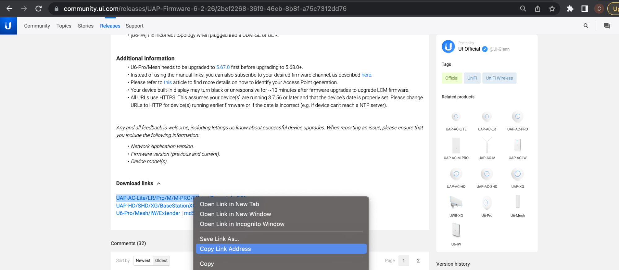
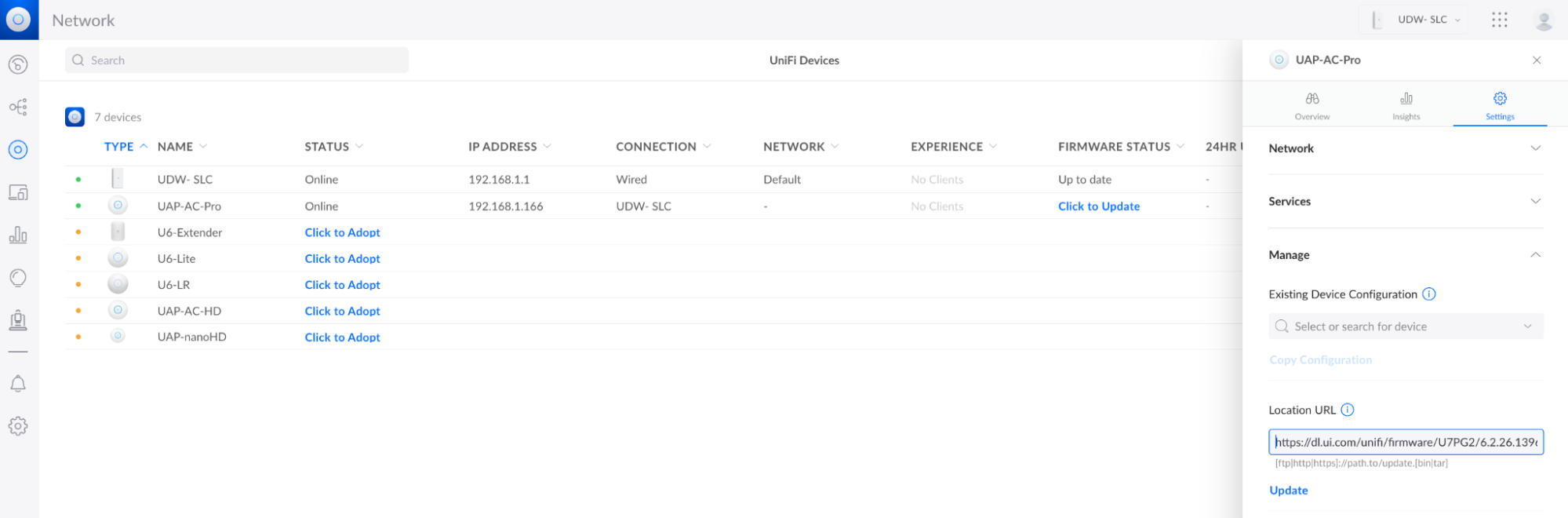
Manually Update UniFi Devices via Web Application
Updating via the Device Property Panel
Use Case: You want to try Early Access firmware releases for specific devices, or you want to return to an official release after trying an EA release.
2. Paste the link in the address bar found in the Settings tab of the device’s properties panel.
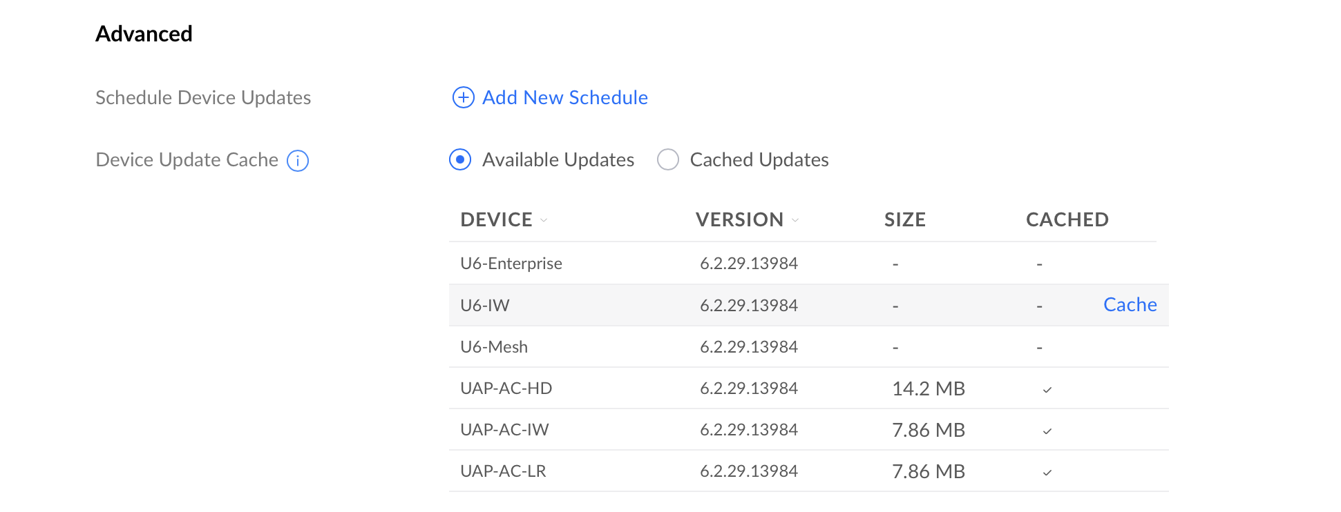
Updating via Your Network Cache
Use Case: You prefer to download and store updates in your Network application so they can be used by other devices, as opposed to downloading multiple, device-specific files from the internet. This is an ideal solution for reducing bandwidth within high-volume networks that host a large number of similar UniFi devices. It is also suitable for the advanced users who disable internet access on their UniFi device’s management network.
Device updates can be cached in your Network application’s System Settings. Once an update is cached, you can open to your UniFi Devices page and click Update Available.
Note: The Cache link will appear when you hover your cursor over an update.
Updating via SSH
Note: SSH updating is not a typical or recommended method. It is only prescribed to work around specific scenarios, such as when:
Prior traditional update attempts have failed. A successful SSH update will help verify if initial failures resulted from incorrect network configuration. For more details, see Troubleshooting Device Updates.
Your UniFi Network device is not being discovered or cannot be adopted because it has been preloaded with outdated firmware.
Your UniFI OS Console cannot be set up because it has been preloaded with an outdated version of UniFi OS.
Run the following command:upgrade paste_download_link_here Exupgrade https://dl.ui.com/unifi/firmware/UAL6/5.60.1.12923/BZ.mt7621_5.60.1+12923.210416.1641.bin
Use the following SCP command to copy the file into the /tmp folder of your device. This requires a compatible SCP application (e.g., Terminal on macOS and Linux, PuTTY/PowerShell on Windows).scp /folder_path/firmwarefile.bin <user>@<IP of device>:/tmp/fwupdate.binExscp /Users/alexpro/Desktop/BZ.mt7621_5.60.1+12923.210416.1641.bin Alex@192.168.1.219:/tmp/fwupdate.bin
Run the following command:ubnt-upgrade paste_download_link_here Exubnt-upgrade https://fw-download.ubnt.com/data/udm/7675-udmpro-1.12.22-36b5213eaa2446aca8486f0b51e64cd3.bin
Use the following SCP command to copy the file into the /mnt/data folder of your device. This requires a compatible SCP application (e.g., Terminal on macOS and Linux, PuTTY/PowerShell on Windows).scp /folder_path/firmwarefile.bin <user>@<IP of device>:/mnt/data/fwupdate.binExscp /Users/alexpro/Desktop/7675-udmpro-1.12.22-36b5213eaa2446aca8486f0b51e64cd3.bin Alex@192.168.1.219:/mnt/data/fwupdate.bin
Run the following command:ubnt-systool fwupdate paste_download_link_here Exubnt-systool fwupdate https://fw-download.ubnt.com/data/unifi-dream/dd49-UDR-2.4.10-cd3afa000ebf4a4fb15374481539961c.bin
UCK G2, UCK G2 Plus, UDM SE, UDR, UDW, UNVR, UNVR Pro (No Internet)
Use the following SCP command to copy the file into the /tmp folder of your device. This requires a compatible SCP application (e.g., Terminal on macOS and Linux, PuTTY/PowerShell on Windows).scp /folder_path/firmwarefile.bin <user>@<IP of device>:/tmp/fwupdate.binExscp /Users/alexpro/Desktop/dd49-UDR-2.4.10-cd3afa000ebf4a4fb15374481539961c.bin
Use the following SCP command to copy the file into the /home/<user> folder of your USG. This requires a compatible SCP application (e.g., Terminal on macOS and Linux, PuTTY/PowerShell on Windows).scp /folder_path/upgrade.tar <user>@<IP of device>:/home/<user>/upgrade.tarExscp /Users/alexpro/Desktop/upgrade.tar Alex@192.168.1.1:/home/Alex/upgrade.tar
Store the new application version on your device using the download link:curl -o “/tmp/unifi_sysvinit_all.deb” <network application link.deb>Excurl -o “/tmp/unifi_sysvinit_all.deb” https://dl.ui.com/unifi/6.2.26-a79cb15f05/unifi_sysvinit_all.deb
Once downloaded, install the new version:apt-get install -y /tmp/unifi_sysvinit_all.deb
Following installation, remove the downloaded file:rm /tmp/unifi_sysvinit_all.deb
Updating Devices in a Broken State
In rare occurrences, a device may stop functioning. UniFi APs may be updated using our TFTP Recovery. This should only be used if your AP completely stops functioning as a last resort prior to submitting an RMA. UniFi OS Consoles and gateways my be updated using Recovery Mode. This should only be used if prompted on your device’s LCM screen.
It may be necessary to provide support files to our team when troubleshooting issues. These contain detailed logs and information about what is happening with your UniFi system. Although sensitive information is generally removed, we do not recommend sharing these publicly.
There are two support files to be aware of:
UniFi OS Support File: This contains logs related to your UniFi OS Console, the installed applications, your adopted UniFi devices, and the client devices connected. Navigating to unifi.ui.com (or signing in locally via IP address) > select your UniFi OS Console > Console Settings > Download Support File. Note that it will have a *.tgz extension.
UniFi Network Support File: This only contains information about your UniFi Network application, your adopted UniFi Network devices, and the connected clients. This should only be used if you are self-hosting the UniFi Network application on a Windows, macOS or Linux machine. Navigate to your UniFi Network Application > Settings > System > Download Network Support File. Note that it will have a *.supp extension.
Advanced
If the UOS Console or UniFi applications are inaccessible and you are not able to download the support file, you can download the logs by following these instructions. Please note, our support engineer will provide detailed information on which of the following will be required for troubleshooting.
1. SSH into the machine: ssh root@192.168.1.1
Note: If you need to change your SSH password, do so in the UniFi OS Settings, by navigating to unifi.ui.com (or signing in locally via IP address) > select your UniFi OS Console > Settings > System.
2. Create ZIP files for the logs. The commands’ format will be: tar -zcvf <file name> <folders path>.
UniFi OS logs: tar -zcvf unifi-core-logs.tar.gz /data/unifi-core/logs/
UniFi local portal (ULP) logs: tar -zcvf ulp-go-logs.tar.gz /data/ulp-go/log/
UniFi Network logs:
For UniFi Dream Machine consoles:tar -zcvf unifi-logs.tar.gz /data/unifi/logs/
For UniFi Cloud Key Gen2 consoles:tar -zcvf unifi-logs.tar.gz /usr/lib/unifi/logs
UniFi Protect logs:
Without external disks: tar -zcvf unifi-protect-logs.tar.gz /data/unifi-protect/logs/
With external disks: tar -zcvf unifi-protect-logs.tar.gz /srv/unifi-protect/logs/
UniFi Talk logs:
tar -zcvf unifi-talk-logs.tar.gz /var/log/unifi-talk/
tar -zcvf unifi-talk-base-logs.tar.gz /var/log/unifi-base/
tar -zcvf unifi-talk-freeswitch-logs.tar.gz /var/log/freeswitch/
UniFi Connect logs: tar -zcvf unifi-connect-logs.tar.gz /data/unifi-connect/log/
System logs:
ubnt-systool support /tmp/system
tar zcvf system.tar.gz /tmp/system
3. Open a new terminal window and run the SCP command to copy the logs from the UniFi OS Console and onto your computer (or system).
Note: The period (.) in the path variable means it will be copied onto the currently opened directory in the terminal. And the asterisk (*) stands for “all”. So the following command will copy everything with the extension tar.gz (i.e. all the logs you prepared in Step 2).
scp root@192.168.1.1:/root/\*.gz .
4. Close both terminal windows to close the sessions.
If other logs are needed, our support agent will guide you and provide the necessary commands.
This article explains what Minimum RSSI is and how to configure it in the UniFi Network application. We only recommend using this if you are familiar with basic RF theory as misconfiguration may result in performance degradation of your network.
Received Signal Strength Indication (RSSI) is a value indicating the perceived signal level of a wireless client from the AP’s perspective. The Minimum RSSI value is set individually on each AP and indicates the minimum signal level required for a client to remain connected.
The main purpose of this is to assist with a client’s roaming between two nearby APs. It prevents a device getting “stuck” connected to the initial AP at a weaker signal strength as opposed to roaming to a new AP that may be more optimal. Once the signal drops below the Minimum RSSI value set, the initial AP will kick the client so that it can reconnect to the new AP.
Once an AP kicks a client (by sending a de-authentication packet), it is up to the client to find a better AP to connect to. It may connect back to the same AP, especially if it is the only one within range. Since the signal strength still does not meet the Minimum RSSI, it will again be booted. Improper tuning can thus result in network instability. For this reason, it is important to realize that there is no one size fits all and you should carefully test your configuration to avoid introducing connectivity problems.
How to determine and configure Minimum RSSI
Minimum RSSI is can be enabled within the UniFi Network Application by selecting an AP in UniFi Devices and then navigating to Settings in the side-panel of the selected device. Once enabled, this can be manually set for your 2G and 5G radios independently.
You can view the Signal Strength for your current wireless clients by clicking on a device in the Client Devices tab. The signal is measured in units of dbm (decibels per milliwatt). You will notice that this is a negative number because the power is less than 1 mW:
dbm = 10 log P1/1mW
0 dBm = 1 mW
-10 dBm = 0.1 mW
-20 dBm = 0.01 mW, and so forth
A value close to 0 indicates high signal quality, whereas a larger negative value indicates poor signal quality. Remember, you need to granularly select the appropriate value for each AP and avoid using a single value everywhere.
Other Considerations
There are many factors that can affect the a client’s RSSI at the AP side including distance, building materials, objects, interference, etc. As much as we would love to give a recommendation, it really isn’t this simple. It’s safe to say -80dBm would be a starting point for standard home or office configurations, but there are too many environmental variables so you should have caution at all times.
The best method to determine appropriate Minimum RSSI values is to perform a site survey. This can be done by testing the signal strength of various wireless clients at different distances. Each device will have different antenna configurations and will thus perform differently in the same geographic location. You want to connect to an SSID, make it specific to that AP (an override on that SSID), and then roam to what you would consider the outer edge of the desired coverage area. Mark the client’s RSSI, and then take a couple more points. The more data you gather, the better idea you’ll get for the minimum RSSI value to use.
HDDs are not required for normal operation, however they expand the functionality by enabling things such as video recording from UniFi Protect, and call recordings and voicemails from UniFi Talk.
We strongly recommend using the UniFi 8TB HDD for UniFi OS Consoles with a 3.5” HDD bay (UDM Pro, UDM SE, UNVR, and UNVR-Pro). These are specialized, industrial-grade drives that can support continuous read and write operations required by a video surveillance system.
Cloud Keys (UCK-G2-PLUS) require a 2.5” HDD for which we strongly recommend continuing to use the drive shipped natively with your equipment. If it will be replaced, the Toshiba 2.5″ 5400RPM 1TB HDD (MQ01ABD100V) appears most stable according to internal testing.
Incorrect drives will result in premature failure which can degrade your entire network’s performance, as well as prevent remote management.
Third-party Drives
If you insist on using a third-party drive, it should meet the following criteria:
It fits inside the HDD tray
3.5” for Dream Machines and Network Video Recorders
2.5” for the UCK Gen2 Plus
It is a surveillance-grade drive designed for continuous load
These are generally 7200RPM, CMR Drives. SMR drives are not recommended and may lead to performance issues, loss of video footage, or even system crashes.
It offers at least 1 TB of storage. No maximum HDD capacity has been established.
If you’re using multiple HDDs with your UniFi OS Console, they must all be the same size.
The total usable storage capacity will be affected based on whether either the redundancy level is set to One Disk (RAID1 / RAID5) or Half of Disks (RAID10).
Incompatible HDDs
Some hard drives require an additional 12V external power supply. These hard drives are not supported by the UCK Gen2 Plus or the UNVR.
The following is a list of 3.5” drives that are confirmed to be incompatible with our UniFi OS Consoles:
Vendor
Series
Model
Capacity
Notes
Seagate
SkyHawk
ST10000VX0004
10TB
Does not fit the drive tray.
Seagate
Ultrathin
ST500LT032
500GB
Does not have bottom screws.
Western Digital
UltraSlim
WD5000MPCK
500GB
Does not have bottom screws and connectors do not fit the tray.
Any
Any
SMR Drives
Any
Drives fit the tray but cause issues.
If you have questions about a particular hard drive or need help choosing a hard drive, please reach out to the Ubiquiti Community for insights and recommendations.
The Internet of Things (IoT) is here, and we’re using it for everything from getting instant answers to random trivia questions to screening visitors at the door. According to Gartner, we were expected to use more than 25 billion internet-connected devices by the end of 2021. But as our digital lives have become more convenient, we might not yet have considered the risks involved with using IoT devices.
How can you keep yourself secure in today’s IoT world, where hackers aim to outsmart your smart home? First we’ll look at how hackers infiltrate the IoT, and then we’ll look at what you can do right now to make sure the IoT is working for you – not against you.
How hackers are infiltrating the Internet of Things
While we’ve become comfortable asking voice assistants to give us the weather forecast while we prep our dinners, hackers have been figuring out how to commandeer our IoT devices for cyber attacks. Here are just a few examples of how cyber criminals are already infiltrating the IoT.
Gaining access to and control of your camera
Have you ever seen someone with a sticker covering the camera on their laptop or smartphone? There’s a reason for that. Hackers have been known to gain access to these cameras and spy on people. This has become an even more serious problem in recent years, as people have been relying on videoconferencing to safely connect with friends and family, participate in virtual learning, and attend telehealth appointments during the pandemic. Cameras now often come with an indicator light that lets you know whether they’re being used. It’s a helpful protective measure, but not a failsafe one.
Using voice assistants to obtain sensitive information
According to Statista, 132 million Americans used a digital voice assistant once a month in 2021. Like any IoT gadget, however, they can be vulnerable to attack. According to Ars Technica, academic researchers have discovered that the Amazon Echo can be forced to take commands from itself, which opens the door to major mischief in a smart home. Once an attacker has compromised an Echo, they can use it to unlock doors, make phone calls and unauthorized purchases, and control any smart home appliances that the Echo manages.
Many bad actors prefer the quiet approach, however, slipping in undetected and stealing information. They can piggyback on a voice assistant’s privileged access to a victim’s online accounts or other IoT gadgets and make off with any sensitive information they desire. With the victim being none the wiser, the attackers can use that information to commit identity fraud or stage even more ambitious cyber crimes.
Hacking your network and launching a ransomware attack
Any device that is connected to the internet, whether it’s a smart security system or even a smart fridge, can be used in a cyber attack. Bad actors know that most people aren’t keeping their IoT gadgets’ software up to date in the same way they do their computers and smartphones, so they take advantage of that false sense of security. Once cyber criminals have gained access to an IoT device, they can go after other devices on the same network. (This is because most home networks are designed to trust devices that are already connected to them.) When these malicious actors are ready, they can launch a ransomware attack that brings your entire digital life to a halt – unless you agree to fork over a hefty sum in bitcoin, that is.
Using bots to launch a DDOS attack
Although most people never notice it, hackers can and do infect IoT devices with malware en masse, gaining control over them in the process. Having turned these zombie IoT devices into bots, the hackers then collectively use them to stage what’s called a botnet attack on their target of choice. This form of assault is especially popular for launching distributed denial of service (DDOS) attacks, in which all the bots in a botnet collectively flood a target with network requests until it buckles and goes offline.
How you can keep your Internet of Things gadgets safe from hackers
So how can you protect your IoT devices from these determined hackers? Fortunately, you can take back control by becoming just a little more cyber smart. Here are a few ways to keep your IoT gadgets safe from hackers:
Never use the default settings on your IoT devices. Although IoT devices are designed to be plug-and-play so you can start enjoying them right away, their default settings are often not nearly as secure as they should be. With that in mind, set up a unique username and strong password combination before you start using any new IoT technology. While you’re at it, see if there’s an option to encrypt the traffic to and from your IoT device. If there is, turn it on.
Keep your IoT software up to date. Chances are, you regularly install the latest software updates on your computer and phone. Hackers are counting on you to leave your IoT gadgets unpatched, running outdated software with vulnerabilities they can exploit, so be sure to keep the software on your IoT devices up to date as well.
Practice good password hygiene. We all slip into bad password habits from time to time – it’s only human – but they put our IoT security at risk. With this in mind, avoid re-using passwords and be sure to set unique, strong passwords on each of your IoT devices. Update those passwords from time to time, too. Don’t store your passwords in a browser, and don’t share them via email. A password manager can help you securely store and share your passwords, so hackers never have a chance to snatch them.
Use secure, password-protected WiFi. Cyber criminals are notorious for sneaking onto open, insecure WiFi networks. Once they’re connected, they can spy on any internet activity that happens over those networks, steal login credentials, and launch cyber attacks if they feel like it. For this reason, make sure that you and your IoT devices only use secure, password-protected WiFi.
Use multi-factor authentication as an extra layer of protection. Multi-factor authentication (MFA), gives you extra security on top of all the other measures we mentioned above. It asks you to provide one more credential, or factor, in addition to a password to confirm you are who you say you are. If you have MFA enabled and a hacker tries to log in as you, you’ll get a notification that a login attempt is in progress. Whenever you have the option to enable MFA on any account or technology, take advantage of it.
Protect your Internet of Things devices with smart password security
The IoT is making our lives incredibly convenient, but that convenience can be a little too seductive at times. It’s easy to forget that smart home devices, harmless-looking and helpful as they are, can be targeted in cyber attacks just like our computers and phones. Hackers are counting on you to leave your IoT gadgets unprotected so they can use them to launch damaging attacks. By following these smart IoT security tips, you can have the best of both worlds, enjoying your smart life and better peace of mind at the same time.
Learn how LastPass Premium helps you strengthen your password security.


 to specify a fixed IP to the NAS: 192.168.1.60. The default gateway should be the same as the LAN IP of your router, which is 192.168.1.100 in our example.

 ” to add the camera configuration, e.g. name, model, IP address, recording setting and recording schedule.


 to play recording and find recent event.


 or
or  to enter the playback page and follow the steps below to play the video files on the remote Surveillance Station.
 .You can examine each channel to know the time range when the files were recorded for each IP camera. The blue cells indicate regular recording files and the red cells indicate alarm recording files. If it is blank, it means no files are recorded at that time.
 to start the playback. You can control the speed and playback direction by dragging the button
  to right or left on the shuttle bar.

 to control all the playback windows to play back the recording files. When this function is enabled, the playback options (play, pause, stop, previous/next frame, previous/next file, speed adjustment) will be applied to all the playback windows.
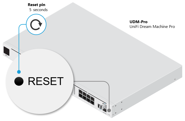