The SonicWall Capture Labs threat research team became aware of an XML External Entity Reference vulnerability affecting Adobe Commerce and Magento Open Source. It is identified as CVE-2024-34102 and given a critical CVSSv3 score of 9.8. Labeled as an Improper Restriction of XML External Entity Reference (‘XXE’) vulnerability and categorized as CWE-611, this vulnerability allows an attacker unauthorized access to private files, such as those containing passwords. Successful exploitation could lead to arbitrary code execution, security feature bypass, and privilege escalation.
A proof of concept is publicly available on GitHub. Adobe Commerce versions 2.4.7, 2.4.6-p5, 2.4.5-p7, 2.4.4-p8, and earlier and Magento Open-Source versions 2.4.7, 2.4.6-p5, 2.4.5-p7, 2.4.4-p8, and earlier are vulnerable. Although Magento Open Source is popular mainly for dev environments, according to Shodan and FOFA, up to 50k exposed Adobe Commerce with Magento template are running.
Technical Overview
Magento (Adobe Commerce) is a built-in PHP platform that helps programmers create eCommerce websites and sell online. It is an HTTP PHP server application. Such applications usually have two global entry points: the User Interface and the API. Magento uses REST API, GraphQL, and SOAP.
Attackers can leverage this vulnerability to gain unauthorized admin access to REST API, GraphQL API, or SOAP API, leading to the disclosure of confidential data, denial of service, server-side request forgery (SSRF), port scanning from the perspective of the machine where the parser is located, and complete compromise of affected systems. This vulnerability poses a significant risk due to its ability to exfiltrate sensitive files, such as app/etc/env.php, containing cryptographic keys used for authentication, as shown in Figure 1. This key is generated during Magento 2 installation process. Unauthenticated actors can utilize this key to forge administrator tokens and manipulate Magento’s APIs as privileged users.
Figure 1: app/etc/env.php
The vulnerability is due to improper handling of nested deserialization in Adobe Commerce and Magento. This allows attackers to exploit XML External Entities (XXE) during deserialization, potentially allowing remote code execution. Unauthorized attackers can craft malicious JSON payloads that represent objects with unintended properties or behaviors when deserialized by the application.
Triggering the Vulnerability
XML External Entities (XXE) attack technique takes advantage of XML’s feature of dynamically building documents during processing. An XML message can provide data explicitly or point to a URI where the data exists. In the attack technique, external entities may replace the entity value with malicious data, alternate referrals, or compromise the security of the data the server/XML application has access to.
In the example below, the attacker takes advantage of an XML Parser’s local server access privileges to compromise local data:
The sample application expects XML input with a parameter called “username.” This parameter is later embedded in the application’s output.
The application typically invokes an XML parser to parse the XML input.
The XML parser expands the entity “test” into its full text from the entity definition provided in the URL. Here, the actual attack takes place.
The application embeds the input (parameter “username,” which contains the file) in the web service response.
The web service echoes back the data.
Attackers may also use External Entities to have the web services server download malicious code or content to the server for use in secondary or follow-on attacks. Other examples wherein sensitive files can be disclosed are shown in Figure 2.
Figure 2: Disclosing targeted files.
Exploiting the Vulnerability
A crafted POST request to a vulnerable Adobe instance with an enabled Magento template is the necessary and sufficient condition to exploit the issue. An attacker only needs to be able to access the instance remotely, which could be over the Internet or a local network. A working PoC with a crafted POST query aids in exploiting this vulnerability. Figure 4 shows a demonstration of exploitation leveraging the publicly available PoC.
Exploiting CVE-2024-34102, steps are enumerated below, which will exfiltrate the contents of the system’s password file from the target server.
Create a DTD file (dtd.xml) on the attacker’s machine. This file includes entities that will read and encode the system’s password file, then send it to your endpoint.
Host the dtd.xml file on the attacker’s machine, accessible via HTTP on a random port.
Send the malicious payload via a sample curl request to the vulnerable Magento instance, as shown in Figure 3. The payload includes a specially crafted XML payload referencing the DTD file hosted on the attacker’s machine.
The XML parser in Magento will process the DTD file, triggering the exfiltration of the system’s password file as shown in Figure 4.
Lastly, observe your endpoint to capture and decode the exfiltrated data.
Figure 3: CVE-2024-34102 attack request
00:00
00:15
Figure 4: CVE-2024-34102 Exploitation
Out of the 50k exposed Magento instances in the wild, multiple events were observed wherein attackers leveraged this vulnerability, as only 25% of instances have been updated since the vulnerability was exploited in the wild. According to Sansec analysis, CVE-2024-34102 can be chained with other vulnerabilities, such as the PHP filter chains exploit (CVE-2024-2961), leading to remote code execution (RCE).
SonicWall Protections
To ensure SonicWall customers are prepared for any exploitation that may occur due to this vulnerability, the following signatures have been released:
IPS: 4462 – Adobe Commerce XXE Injection
Remediation Recommendations
Considering the severe consequences of this vulnerability and the trend of nefarious activists trying to leverage the exploit in the wild, users are strongly encouraged to upgrade their instances, according to Adobe advisory, to address the vulnerability.
By: Shannon Murphy, Greg Young March 20, 2024 Read time: 2 min (589 words)
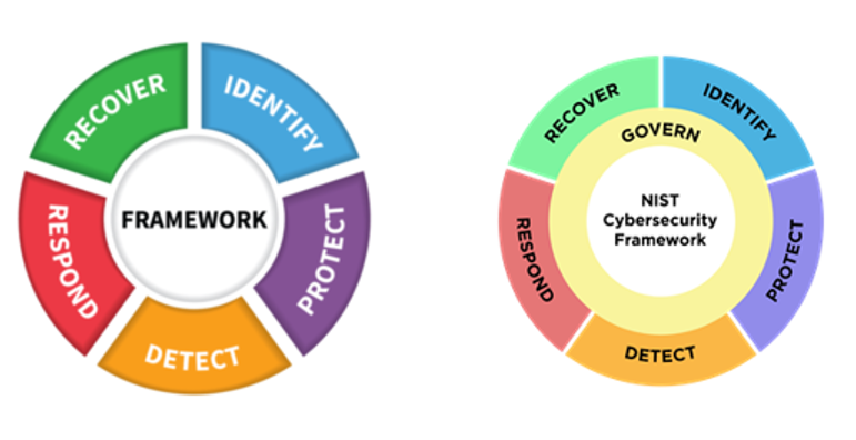
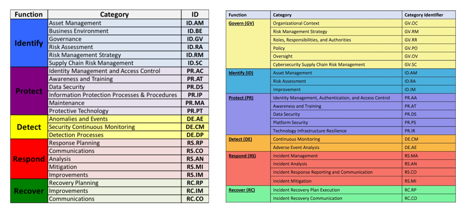
On February 26, 2024, the National Institute of Standards and Technology (NIST) released the official 2.0 version of the Cyber Security Framework (CSF).
What is the NIST CSF?
The NIST CSF is a series of guidelines and best practices to reduce cyber risk and improve security posture. The framework is divided into pillars or “functions” and each function is subdivided into “categories” which outline specific outcomes.
As titled, it is a framework. Although it was published by a standards body, it is not a technical standard.
https://www.nist.gov/cyberframework
What Is the CSF Really Used For?
Unlike some very prescriptive NIST standards (for example, crypto standards like FIPS-140-2), the CSF framework is similar to the ISO 27001 certification guidance. It aims to set out general requirements to inventory security risk, design and implement compensating controls, and adopt an overarching process to ensure continuous improvement to meet shifting security needs.
It’s a high-level map for security leaders to identify categories of protection that are not being serviced well. Think of the CSF as a series of buckets with labels. You metaphorically put all the actions, technology deployments, and processes you do in cybersecurity into these buckets, and then look for buckets with too little activity in them or have too much activity — or repetitive activity — and not enough of other requirements in them.
The CSF hierarchy is that Functions contain many Categories — or in other words, there are big buckets that contain smaller buckets.
What Is New in CSF 2.0?
The most noteworthy change is the introduction of Governance as a sixth pillar in the CSF Framework. This shift sees governance being given significantly more importance from just a mention within the previous five Categories to now being its owna separate Function.
According to NIST the Govern function refers to how an organization’s, “cybersecurity risk management strategy, expectations, and policy are established, communicated, and monitored.” This is a positive and needed evolution, as when governance is weak, it often isn’t restricted to a single function (e.g. IAM) and can be systemic.
Governance aligns to a broader paradigm shift where we see cybersecurity becoming highly relevant within the business context as an operational risk. The Govern expectation is cybersecurity is integrated into the broader enterprise risk management strategy and requires dedicated accountability and oversight.
There are some other reassignments and minor changes in the remaining five Categories. CSF version 1.0 was published in 2014, and 1.1 in 2018. A lot has changed in security since then. The 2.0 update acknowledges that a review has been conducted.
As a framework, the CISO domain has not radically changed. Yes, the technology has radically evolved, but the greatest evolution in the CISO role really has been around governance: greater interaction with C-suite and board, while some activities have been handed off to operations.
So How Will This Impact Me in the Short Term?
The update to the NIST CSF provides a fresh opportunity to security leaders to start or reopen conversations with business leaders on evolving needs.
The greatest impact will be to auditors and consultants who will need to make formatting changes to their templates and work products to align with version 2.0.
CISOs and security leaders will have to make some similar changes to how they track and report compliance.
But overall, the greatest impact (aside from some extra billable cybersecurity consulting fees) will be a boost of relevance to the CSF that could attract new adherents both through security leaders choosing to look at themselves through the CSF lens and management asking the same of CISOs.
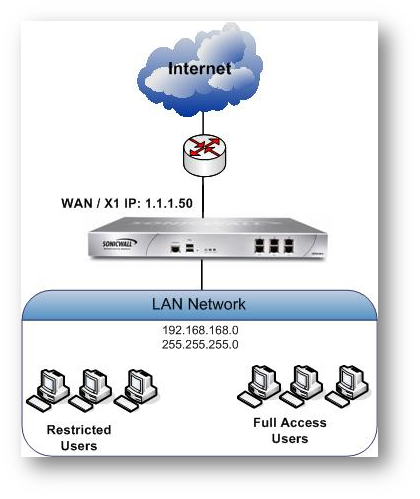
This article explains about how to integrate Content Filtering Service with LDAP (With Single Sign On) by using SonicOS 7.0.1 or older.
Restricted user group on the active directory is imported to SonicWall and give restricted web access to those users in that group.
Where in the Full Access User group has full access or partial access to websites.
Resolution
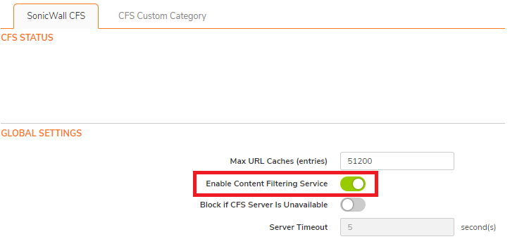
Enable Content Filtering Service from Policy | Security Services | Content Filter
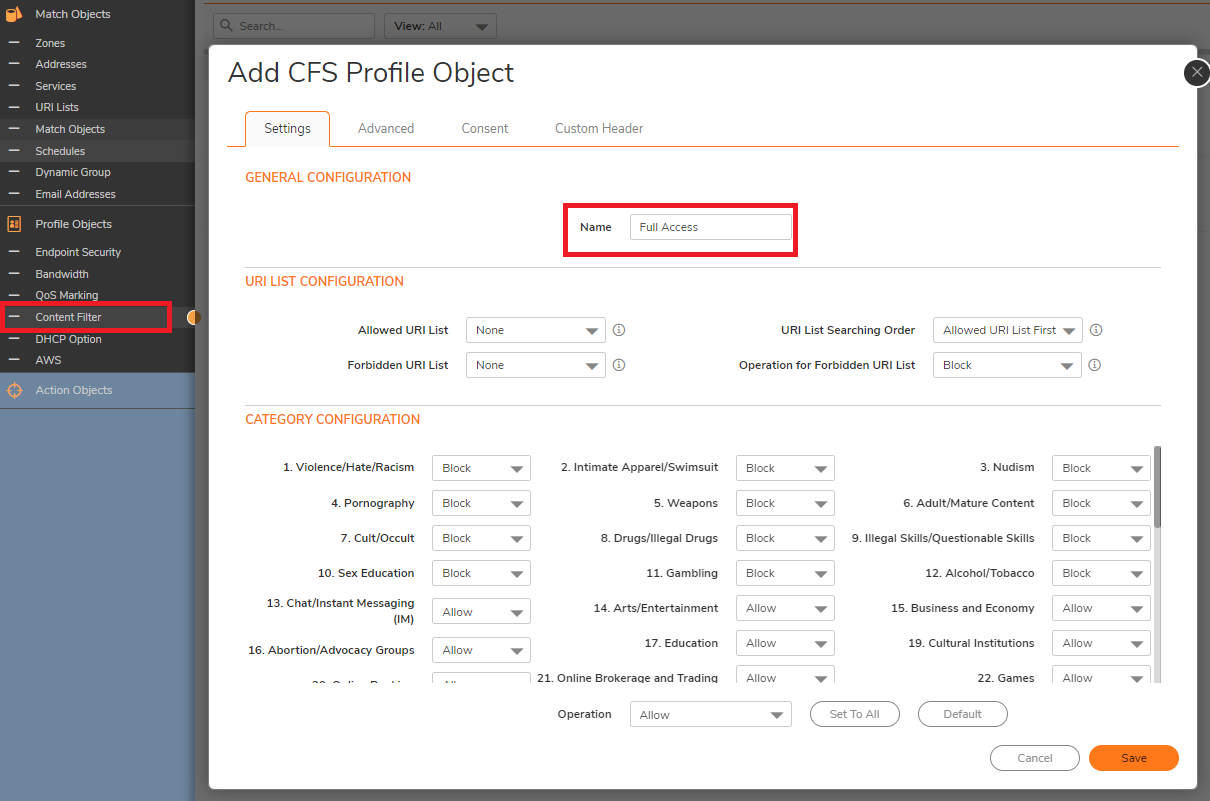
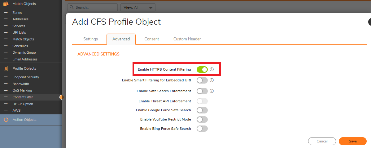
Navigate to Profile Objects| Content Filter and access the Profile Objects tab. Create the new Content Filter Profile and Allow/Block for each category according with your need.
Make sure to Enable HTTPS content Filtering. This option is disabled by default.
4. Create another Content Filter Profile as Restricted Access CFS Policy for Restricted User Group.Click on Add, Add a Policy for Restricted Group with most of the categories enabled (Depends on what should be Blocked)
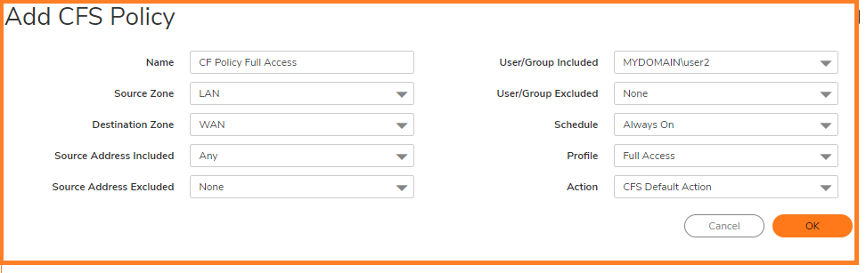
5. Creating a Full Access CFS Policy for Full Access User Group.Add second Policy for the Full Access Group with certain category enabled or all categories enabled (Depends on what should be allowed).
Configuring LDAP on SonicWall
For more information about how to enable LDAP on Sonicwall, please reach below link.
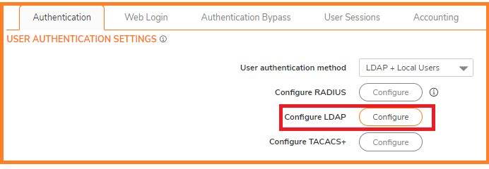
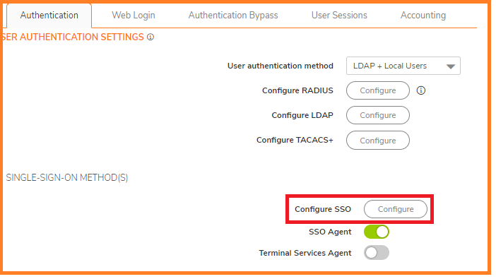
Navigate to Users | Settings page, in the Authentication method for login drop-down list, select LDAP + Local Users and click Configure.
On the Settings tab of the LDAP Configuration window, configure the following fields.
Name or IP address: IP address of the LDAP serverPort Number: 389 (Default LDAP Port)Server timeout (seconds): 10 Seconds (Default)Overall operation timeout (minutes): 5(Default)Select Give login name/location in tree
On the Login/Bind, Give login name/loction in three. Set the admin user and password to access on your LDAP server.
On the Schema tab, configure the following fields: LDAP Schema:Microsoft Active Directory.
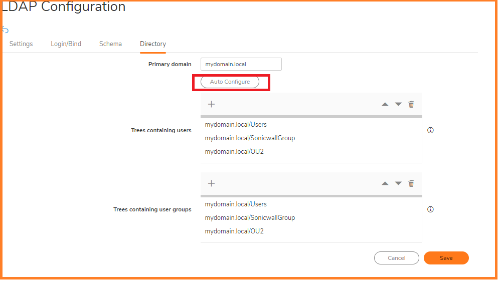
On the Directory tab, configure the following fields.
Primary domain:The user domain used by your LDAP implementation.
User tree for login to server:The location of where the tree is that the user specified in the settings tab.
Click Auto-configure. (This will populate the Trees containing users and Trees containing user groups fields by scanning through the directories in search of all trees that contain user objects.)
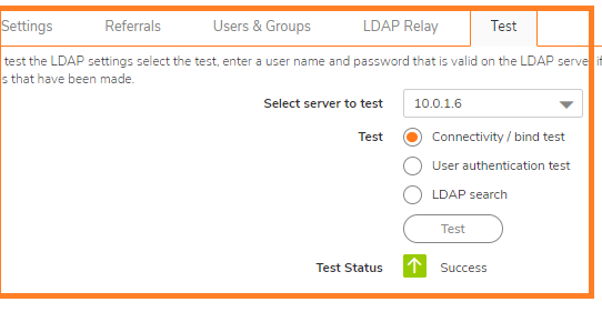
On the LDAP Test tab, Test LDAP connectivity to make sure that the communication is successful.
Importing Groups from LDAP to the SonicWall unit
Navigate to Users | Local Groups.
Click Import from LDAP
Click Configure for the Group that is imported from LDAP.
Go to CFS Policy tab , Select the appropriate CFS Policy from the drop down and Click OK.
Configuring Single Sign-On Method on SonicWall
For more information about how to enable SSO Agent and Enable SSO on Sonicwall, please reach below link.
In the Single-sign-on method , select SonicWall SSO Agent and Configure
Click Configure button. The SSO configuration page is displayed.
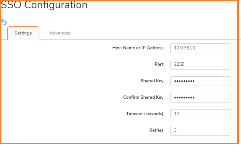
Under the Settings tab, Click Add button to add the IP address of the work station that has SSO agent running.
Click on the ADD button: settings window is displayed
In the HostName or IP Address field, enter the name or IP Address of the workstation on which SonicWall SSO Agent is installed
In Port Number, enter the port number of the workstation on which SonicWall SSO Agent is installed. The default port is 2258
In the Shared Key field, enter the shared key that you created or generated in the SonicWall SSO Agent. The shared key must match exactly. Re-enter the shared key in the Confirm Shared Key field. Click Apply.
Once the SSO Agent is successfully added, under the Authentication Agent Settings a green light is shown for status.
Click Test tab. The Test Authentication Agent Settings page displays.
Select the Check agent connectivity radio button then click the Test button. This will test communication with the authentication agent. If the SonicWall security appliance can connect to the agent, you will see the message Agent is ready.
Select the Check user radio button, enter the IP address of a workstation in the Workstation IP address field, then click Test. This will test if the agent is property configured to identify the user logged into a workstation.
NOTE: Performing tests on this page applies any changes that have been made. TIP: If you receive the messages Agent is not responding or Configuration error, check your settings and perform these tests again.
When you are finished, click OK.
Enabling CFS for the LAN Zone and applying Imported LDAP Group
CAUTION: It is not recommended to do this change on a Production Environment because this changes are instant and can affect all the computers on the LAN. So it is best to schedule a downtime before proceeding further.
Navigate to Network | Zones, click Configure Button for LAN Zone.
Check the box Enforce Content Filtering Service, select the Default CFS Policy from the drop down.
How to TEST
Log out from the windows domain computer and log in back with a user from either the full access or restricted access groups and check whether the policy is getting enforced correctly for the user.
This article helps answer frequently asked questions regarding SonicOS 7.1.1.
Q. What is SonicOS 7.1.1? A. SonicOS 7.1.1 is the feature release available on all Gen 7 firewalls which brings in new capabilities around security, content filtering, integrations and virtual platforms.
Q. Will we be able to manage SonicOS 7.1 from NSM 2.3.5? A. NSM 2.3.5 will not support SonicOS 7.1. The support for SonicOS 7.1 will be available from NSM 2.4.0, which will be released early next year (2024). Please read the following article on NSM Compatibility with SonicOS 7.1.
Q. What are the new features available on SonicOS 7.1.1? A. The major features implemented in SonicOS 7.1.1 are DNS Filtering, reputation-based content filtering, Wi-Fi 6 access-point management, Network Access Control (NAC) integration with Aruba ClearPass, NSv bootstrapping, auto-update firmware and some other enhancements with storage and user interface (UI) for ease of use.
Q. How can existing firewall customers running SonicOS 7 upgrade/migrate to SonicOS 7.1.1? A. You can upgrade the firewall to SonicOS 7.1 on box without using a migration tool.
Q. How can existing firewall customers running SonicOS6.5 and previous versions upgrade to SonicOS 7.1.1? A. Users will be required to make use of our Secure Upgrade Program to upgrade their existing hardware models to Gen 7. They will then need to migrate their settings to the new firewall running 7.1.1 OS Learn more about the Secure Upgrade Program
Q. Are there any new features in 7.1.1 that will require new licenses? A. The DNS Filtering feature is a licensed feature that will be available as an a la carte license for Gen 7 firewalls without the APSS bundle.
Q. Do I need any additional licensing if I already have the APSS license available on my current Gen 7 firewall? A. No.
Q. Can I perform a firmware/OS upgrade on my existing NSv NGFW running SonicOS 7.1.1? A. The downgrade of firmware from SonicOS 7.1 to SonicOS 7.0 is not supported. Please refer to this article when upgrading your firewall: How can I upgrade SonicOS Firmware?
Q. Is there any change in behavior with regard to Policy Mode with 7.1.1? A. There is no change in behavior with regard to Policy Mode in SonicOS 7.1.1. The NSv 270, 470 and 870 will continue to support both Global and Policy Mode. The NSsp15700 will continue to support only Policy Mode.
Q. What is CFS 5.0? How does it differ from CFS 4.0? A. Content Filtering Service 5.0 brings category extension with CFS 4.0. SonicOS 7.0.1 supported 64 categories and that has been increased to 89. Content Filtering 5.0 brings in performance improvements along with reputation-based blocking.
Q. What is upgrade behavior when a user upgrades from SonicOS 7.0.1 to SonicOS 7.1.1 with regard to CFS policies? A. There will be no impact on the existing CFS policies, however as CFS 5.0 brings in reputation-based blocking, users will be required to configure the CFS policies with the new reputation parameter in CFS 5.0. Please refer to this upgrade article.
Q. Can we downgrade the firewall from SonicOS 7.1 to SonicOS 7.0? A. The downgrade of firmware from SonicOS 7.1 to SonicOS 7.0 is not supported. Please refer to this article when upgrading your firewall.
Q. What is DNS Filtering? How is it different from the current DNS capabilities in SonicOS 7.0.1? A. DNS Filtering inspects the DNS traffic in real time and provides the ability to block threats and access to malicious websites. DNS Filtering blocks threats before they can reach your network. The DNS security capabilities on 7.0.1 include DNS Tunnel Detection and DNS Sinkholes. Please read DNS Security to understand them in detail.
Q. What is the upgrade behavior when users upgrade from SonicOS 7.0.1 to SonicOS 7.1.1 with regard to DNS proxy and sink-holing? A. The upgrade from SonicOS 7.0.1 to SonicOS 7.1.1 would have no impact on the behavior that was there previous to the SonicOS 7.1 upgrade.
Q. What does the NAC integration feature do? A. SonicWall Next-Generation Firewalls (NGFWs) provide Restful threat API which integrates with Aruba ClearPass as network access control (NAC). ClearPass can pass the security context vectors using the restful API which is included with SonicWall NGFWs. ClearPass can pass security context vectors including Source IP, Source MAC, User ID, User Role, Domain, Device Category, Device Family, Device Name, OS Type, Hostname and Health Posture to SonicWall NGFWs to enforce real-time rules based on Device Type, OS and Device Health Posture at every point of control. When an alert is generated on a client machine, it can be shared by ClearPass to SonicWall NGFWs which would trigger a range of predetermined, policy-based actions from quarantine to blocking.
Q. Does this NAC integration feature work with any NAC providers? A. No, this NAC integration only works with Aruba ClearPass.
Q. Which access point models can I integrate with firewalls running SonicOS 7.1.1? A. With the launch of SonicOS 7.1.1, users will now also be able to integrate and manage Wi-Fi 6 APs like 621, 641 and 681.
Q. How can I automate NSv deployment using the bootstrapping feature? Which platforms support this feature? Bootstrapping helps with NSv automated deployments. Token-based registration will help ease the bootstrapping process. KVM already supported bootstrapping in SonicOS 7.0.1. With the launch of 7.1.1, other platforms like VMWare, Hyper-V, AWS and Azure will also support bootstrapping features.
Q. How is the bootstrapping process different between private cloud and public cloud? A. The bootstrapping process is not different between private cloud and public cloud. SonicOS supports bootstrapping on AWS, Azure, VMware, KVM and Hyper-V.
Q. What are the new parameters that will be stored in secondary storage modules with the launch of 7.1.1? A. TSR , exp, PCAP, threat logs and appflow logs will be stored in the secondary storage module as part of SonicOS 7.1.1
Q. Will the new features available in SonicOS 7.1.1 be available in the Capture Threat Assessment (CTA) report? A. During the launch, the new features in SonicOS 7.1.1 will not be included in the CTA report.
Q. Are the new features available on NSM? A. Yes. The upcoming NSM version 2.4 is planned to support the new features on SonicOS 7.1.1.
Q. Can I manage SonicOS 7.1.1 on the previous versions of NSM (prior to 2.4)? A. You can upgrade the SonicOS version to 7.1.1, but the new features which are part of 7.1.1 will not be available on NSM versions prior to 2.4
Q. What are the best practices to be followed on SonicOS 7.1.1? A. Please follow the best practices when upgrading the firewall from SonicOS 7.0.1 to SonicOS 7.1 documented here.
The migration tool is not required for the configuration migration from SonicOS 7.0 to SonicOS 7.1. Any customer migrating from Gen 6 to SonicOS 7.1 would need to upgrade to SonicOS 7.0.1 using the migration tool and then migrate to SonicOS 7.1.
DNS Filtering is the first line of defense and works independent of Content Filtering Services (CFS). Please follow the admin guides for seamless configuration with best practices.
Q. What is the new website for URL rating and reputation lookup with CFS 5.0? A. https://cfssupportapi.global.sonicwall.com/
Q. How can I check the URL rating on the firewall UI? A. Device –> Diagnostics –> URL Rating Request Tool
Q. What is the performance impact of enabling the new SonicOS 7.1 features on an existing firewall? A. We do not expect there to be any impact on the performance of an existing firewall because of new features.
Q. Can DNS proxy 4to4 and 4to6 features work alongside DNS filtering? Can this be accomplished by adding an additional DNS proxy-only rule alongside a DNS filtering rule for X0 Interface? If so, what will take precedence/priority? A. DNS rules give the choice of either proxy or filtering on a single rule. When proxy is enabled, Client 4to4 or 4to6 DNS queries can be proxied. When DNS filtering is enabled, only Client 4to4 Requests DNS queries will be proxied and filtered. —While DNS proxies will process both DNS TCP and DNS UDP, DNS filtering is only for DNS UDP. —Both proxy or filtering DNS rules can be stacked, the most specific match will be applied, and the lookup precedence/priority is top-down. —To have DNS proxy 4to6 alongside DNS filtering, the proxy rule must explicitly have source zone and address of the 4to6 Clients for the traffic to hit the rule and the policy to be applied
Q. Can DNS Filtering be applied on custom zones or is it restricted to default zones, LAN, DMZ and WLAN? A. DNS Filtering can be applied to LAN, DMZ and WLAN zones as well as custom zones with Trusted, Public and Wireless Security Types.
Q. How long does a cache entry last before we request a category for a specific domain again? A. The cache entry of a domain would depend on the TTL of the domain.
Q. Are there plans to support DNS over TLS and DNS over HTTPS? A. Yes. DNS over TLS and DNS over HTTPS will be available in a future release.
Q. Will the DNS Filtering license be included with any existing bundle or does the customer need to buy it separately? A. DNS Filtering will be available with APSS and there will be a la carte SKUs for EPSS, TPSS and HW only.
Q. What happens to the WNM managed access-point when the firewall is upgraded to SonicOS 7.1?
A. Please note that if you have 600 series access points on the network connected to a WLAN zone of a firewall with 7.0.x managed by WNM, after the update to 7.1 the access points will be acquired by the firewall. All WNM settings will not be available. Please “Disable SonicPoint/SonicWave management” on the WLAN zone for seamless management.
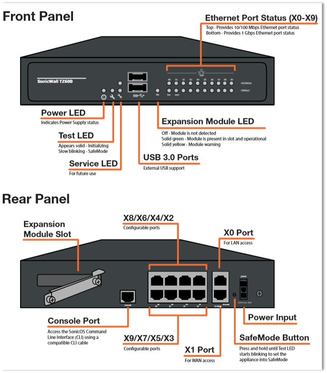
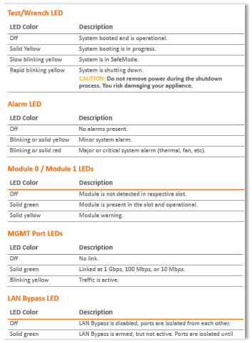
NOTE: In the SonicWall TZ Series appliances there are two Service LEDs, which are reserved to reflect “Services” in the future, however in current SonicOS versions, they are used to reflect presence of the Alarms.
The Test and Alarm LEDs illuminate yellow or red. These LEDs can blink, flash, heartbeat or show a solid light.
Blink is a repetitive rapid on/off cycle (on second, off second).
A flash is a single slow on/off cycle.
Heartbeat is a double flash, repetitive on/off cycle (on 1/15th second, off 1/6th second, on 1/15th second, off second).
LABEL
STATE
MEANING
PWR/PWR1/PWR2
BlueYellowOff
Power is On.Power Supply Not Functioning Correctly.No AC Cable plugged in or On/Off switch at the back of the product is on 0.
What is the minimum recommended length of twisted pair copper cable that I should use with my SonicWall firewalls’ HA ports for high availability?
Resolution
Question:
What is the minimum recommended length of twisted pair copper cable that I should use with my SonicWall firewalls’ HA ports for high availability?
Answer:
At present, there is no officially published minimum length for a twisted pair cable from IEEE or ANSI, though there is information about maximum lengths for twisted pair cable.
However, sometimes customers want to use a cable that is only several inches in length for this. The reason why is because it looks neat and tidy, and it’s one less cable that has to be strung through a rackmount cable channel. However, using such a small cable often causes problems. Customers have reported issues where the firewalls appear to lock up, and they can neither be managed, nor can they pass traffic.
The reason why this occurs, is because the extremely short HA cable causes problems with the transmissions of the HA heartbeats. In an HA pair, when the idle unit does not receive heartbeats for the configured interval and time threshold, it will go active. However, if the other unit in the HA pair is still active, both units’ interfaces will be competing for the addressing, which means there is an IP conflict between all of each firewall’s interfaces. This will prevent the devices from being managed, and it will also prevent them from passing traffic.
With regards to cable length, the following needs to be considered: — 1.) Crosstalk
Crosstalk is when a signal sent on one circuit interferes with another signal sent on a separate but adjacent circuit. This is usually caused by circuits being close together. With ethernet cabling, this effect is reduced by twisting the circuit pairs. This reduces the circuits’ ability to interfere with one another while traveling the length of the copper media. With an extremely short cable, there is usually not enough twisted pair to prevent crosstalk interference.
2.) Return Loss
Return loss is essentially the loss of a signal’s power which is returned or reflected by a discontinuity in the cabling (ie: a point in the transmission line where the signal cannot conduct fully to the next leg of the pathway). It is desirable to have a high level of return loss (ie: the loss of reflectivity). Low return loss can be caused by problems at the termination point of the cable, or by a device which is in line with the transmission pathway. A shorter cable presents a potential for lower return loss, because there is less wire to degrade the reflection of signals.
3.) Cable Quality
The quality of cabling will vary from vendor to vendor, depending upon how accurate the equipment is which is used in the manufacturing process. Some vendors do not twist their cabling as effeciently as others do, and some have lower-quality crimps than others. Cables which are crimped by individuals often suffer greatly by comparison to manufactured cables, as one can only be so precise with a hand-crimping tool. The most common problem with custom cables is a loss of twisting near the termination point of the cable. Most vendors who make cables less than half of 1 meter in length do not have those cables certified by any standards body.
For high availability, SonicWall support recommends using a patch or crossover (NSA units have MDIx autosensing capabilities on their interfaces) cable which is no shorter than 1 meter in length (about three feet). There are many posted discussions on this topic available to read online, however, this post from a Fluke Networks employee at forucms.bicsi.org sums up these discussions very well.
http://forums.bicsi.org/Topic2210-4-1.aspx#bm2215 —- “If you are talking specifically about patch cords, then 0.5 m is the implied minimum length in ANSI/TIA/EIA-568-B.2-1 for a certified patch cord. That’s because the math for the limit lines really does not work below this. Infact, getting a certified patch cord of 0.5 is going to be tricky. Many vendors only offer a certified patch cord of 1.0 m or longer.”
Dirk Schrader Published: November 14, 2023 Updated: November 24, 2023
In the wake of escalating cyber-attacks and data breaches, the ubiquitous advice of “don’t share your password” is no longer enough. Passwords remain the primary keys to our most important digital assets, so following password security best practices is more critical than ever. Whether you’re securing email, networks, or individual user accounts, following password best practices can help protect your sensitive information from cyber threats.
Read this guide to explore password best practices that should be implemented in every organization — and learn how to protect vulnerable information while adhering to better security strategies.
The Secrets of Strong Passwords
A strong password is your first line of defense when it comes to protecting your accounts and networks. Implement these standard password creation best practices when thinking about a new password:
Complexity: Ensure your passwords contain a mix of uppercase and lowercase letters, numbers, and special characters. It should be noted that composition rules, such as lowercase, symbols, etc. are no longer recommended by NIST — so use at your own discretion.
Length: Longer passwords are generally stronger — and usually, length trumps complexity. Aim for at least 6-8 characters.
Unpredictability: Avoid using common phrases or patterns. Avoid using easily guessable information like birthdays or names. Instead, create unique strings that are difficult for hackers to guess.
Combining these factors makes passwords harder to guess. For instance, if a password is 8 characters long and includes uppercase letters, lowercase letters, numbers and special characters, the total possible combinations would be (26 + 26 + 10 + 30)^8. This astronomical number of possibilities makes it exceedingly difficult for an attacker to guess the password.
Of course, given NIST’s updated guidance on passwords, the best approach to effective password security is using a password manager — this solution will not only help create and store your passwords, but it will automatically reject common, easy-to-guess passwords (those included in password dumps). Password managers greatly increase security against the following attack types.
Password-Guessing Attacks
Understanding the techniques that adversaries use to guess user passwords is essential for password security. Here are some of the key attacks to know about:
Brute-Force Attack
In a brute-force attack, an attacker systematically tries every possible combination of characters until the correct password is found. This method is time-consuming but can be effective if the password is weak.
Strong passwords help thwart brute force attacks because they increase the number of possible combinations an attacker must try, making it unlikely they can guess the password within a reasonable timeframe.
Dictionary Attack
A dictionary attack is a type of brute-force attack in which an adversary uses a list of common words, phrases and commonly used passwords to try to gain access.
Unique passwords are essential to thwarting dictionary attacks because attackers rely on common words and phrases. Using a password that isn’t a dictionary word or a known pattern significantly reduces the likelihood of being guessed. For example, the string “Xc78dW34aa12!” is not in the dictionary or on the list of commonly used passwords, making it much more secure than something generic like “password.”
Dictionary Attack with Character Variations
In some dictionary attacks, adversaries also use standard words but also try common character substitutions, such as replacing ‘a’ with ‘@’ or ‘e’ with ‘3’. For example, in addition to trying to log on using the word “password”, they might also try the variant “p@ssw0rd”.
Choosing complex and unpredictable passwords is necessary to thwart these attacks. By using unique combinations and avoiding easily guessable patterns, you make it challenging for attackers to guess your password.
How Password Managers Enhance Security
Password managers are indispensable for securely storing and organizing your passwords. These tools offer several key benefits:
Security: Password managers store passwords and enter them for you, eliminating the need for users to remember them all. All users need to remember is the master password for their password manager tool. Therefore, users can use long, complex passwords as recommended by best practices without worrying about forgetting their passwords or resorting to insecure practices like writing passwords down or reusing the same password for multiple sites or applications.
Password generation: Password managers can generate a strong and unique password for user accounts, eliminating the need for individuals to come up with them.
Encryption: Password managers encrypt password vaults, ensuring the safety of data — even if it is compromised.
Convenience: Password managers enable users to easily access passwords across multiple devices.
When selecting a password manager, it’s important to consider your organization’s specific needs, such as support for the platforms you use, price, ease of use and vendor breach history. Conduct research and read reviews to identify the one that best aligns with your organization’s requirements. Some noteworthy options include Netwrix Password Secure, LastPass, Dashlane, 1Password and Bitwarden.
How Multifactor Authentication (MFA) Adds an Extra Layer of Security
Multifactor authentication strengthens security by requiring two or more forms of verification before granting access. Specifically, you need to provide at least two of the following authentication factors:
Something you know: The classic example is your password.
Something you have: Usually this is a physical device like a smartphone or security token.
Something you are: This is biometric data like a fingerprint or facial recognition.
MFA renders a stolen password worthless, so implement it wherever possible.
Password Expiration Management
Password expiration policies play a crucial role in maintaining strong password security. Using a password manager that creates strong passwords also has an influence on password expiration. If you do not use a password manager yet, implement a strategy to check all passwords within your organization; with a rise in data breaches, password lists (like the known rockyou.txt and its variations) used in brute-force attacks are constantly growing. The website haveibeenpawned.com offers a service to check whether a certain password has been exposed. Here’s what users should know about password security best practices related to password expiration:
Follow policy guidelines: Adhere to your organization’s password expiration policy. This includes changing your password when prompted and selecting a new, strong password that meets the policy’s requirements.
Set reminders: If your organization doesn’t enforce password expiration via notifications, set your own reminders to change your password when it’s due. Regularly check your email or system notifications for prompts.
Avoid obvious patterns: When changing your password, refrain from using variations of the previous one or predictable patterns like “Password1,” “Password2” and so on.
Report suspicious activity: If you notice any suspicious account activity or unauthorized password change requests, report them immediately to your organization’s IT support service or helpdesk.
Be cautious with password reset emails: Best practice for good password security means being aware of scams. If you receive an unexpected email prompting you to reset your password, verify its authenticity. Phishing emails often impersonate legitimate organizations to steal your login credentials.
Password Security and Compliance
Compliance standards require password security and password management best practices as a means to safeguard data, maintain privacy and prevent unauthorized access. Here are a few of the laws that require password security:
HIPAA (Health Insurance Portability and Accountability Act): HIPAA mandates that healthcare organizations implement safeguards to protect electronic protected health information (ePHI), which includes secure password practices.
PCI DSS (Payment Card Industry Data Security Standard): PCI DSS requires organizations that handle payment card data on their website to implement strong access controls, including password security, to protect cardholder data.
GDPR (General Data Protection Regulation): GDPR requires organizations that store or process the data of EU residents to implement appropriate security measures to protect personal data. Password security is a fundamental aspect of data protection under GDPR.
FERPA (Family Educational Rights and Privacy Act): FERPA governs the privacy of student education records. It includes requirements for securing access to these records, which involves password security.
Organizations subject to these compliance standards need to implement robust password policies and password security best practices. Failure to do so can result in steep fines and other penalties.
There are also voluntary frameworks that help organizations establish strong password policies. Two of the most well known are the following:
NIST Cybersecurity Framework: The National Institute of Standards and Technology (NIST) provides guidelines and recommendations, including password best practices, to enhance cybersecurity.
ISO 27001: ISO 27001 is an international standard for information security management systems (ISMSs). It includes requirements related to password management as part of its broader security framework.
Password Best Practices in Action
Now, let’s put these password security best practices into action with an example:
Suppose your name is John Doe and your birthday is December 10, 1985. Instead of using “JohnDoe121085” as your password (which is easily guessable), follow these good password practices:
Create a long, unique (and unguessable) password, such as: “M3an85DJ121!”
If you are looking to strengthen your security, follow these password best practices:
Remove hints or knowledge-based authentication: NIST recommends not using knowledge-based authentication (KBA), such as questions like “What town were you born in?” but instead, using something more secure, like two-factor authentication.
Encrypt passwords: Protect passwords with encryption both when they are stored and when they are transmitted over networks. This makes them useless to any hacker who manages to steal them.
Avoid clear text and reversible forms: Users and applications should never store passwords in clear text or any form that could easily be transformed into clear text. Ensure your password management routine does not use clear text (like in an XLS file).
Choose unique passwords for different accounts: Don’t use the same, or even variations, of the same passwords for different accounts. Try to come up with unique passwords for different accounts.
Use a password management: This can help select new passwords that meet security requirements, send reminders of upcoming password expiration, and help update passwords through a user-friendly interface.
Enforce strong password policies: Implement and enforce strong password policies that include minimum length and complexity requirements, along with a password history rule to prevent the reuse of previous passwords.
Update passwords when needed: You should be checking and – if the results indicate so – updating your passwords to minimize the risk of unauthorized access, especially after data breaches.
Monitor for suspicious activity: Continuously monitor your accounts for suspicious activity, including multiple failed login attempts, and implement account lockouts and alerts to mitigate threats.
Educate users: Conduct or partake in regular security awareness training to learn about password best practices, phishing threats, and the importance of maintaining strong, unique passwords for each account.
Implement password expiration policies: Enforce password expiration policies that require password changes at defined circumstances to enhance security.
How Netwrix Can Help
Adhering to password best practices is vital to safeguarding sensitive information and preventing unauthorized access.
Netwrix Password Secure provides advanced capabilities for monitoring password policies, detecting and responding to suspicious activity and ensuring compliance with industry regulations. With features such as real-time alerts, comprehensive reporting and a user-friendly interface, it empowers organizations to proactively identify and address password-related risks, enforce strong password policies, and maintain strong security across their IT environment.
Conclusion
In a world where cyber threats are constantly evolving, adhering to password management best practices is essential to safeguard your digital presence. First and foremost, create a strong and unique password for each system or application — remember that using a password manager makes it much easier to adhere to this critical best practice. In addition, implement multifactor authentication whenever possible to thwart any attacker who manages to steal your password. By following the guidelines, you can enjoy a safer online experience and protect your valuable digital assets.
Dirk Schrader is a Resident CISO (EMEA) and VP of Security Research at Netwrix. A 25-year veteran in IT security with certifications as CISSP (ISC²) and CISM (ISACA), he works to advance cyber resilience as a modern approach to tackling cyber threats. Dirk has worked on cybersecurity projects around the globe, starting in technical and support roles at the beginning of his career and then moving into sales, marketing and product management positions at both large multinational corporations and small startups. He has published numerous articles about the need to address change and vulnerability management to achieve cyber resilience.
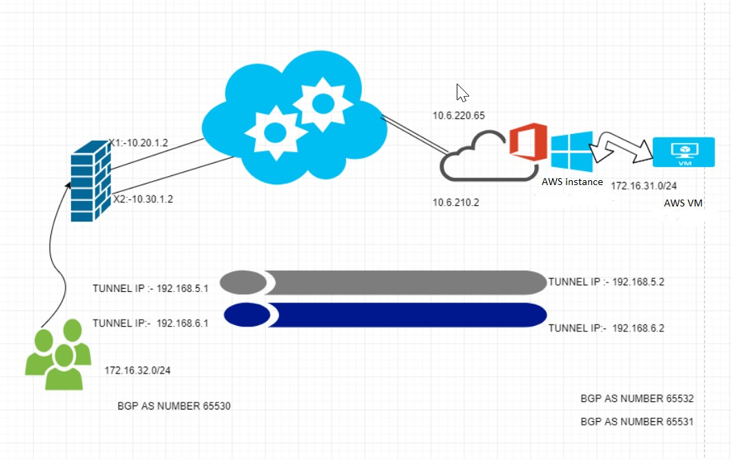
This article details how to configure a Site-to-Site VPN between AWS and SonicWall using Tunnel interface and Applying a Route map to influence the incoming and outgoing traffic.
Below is the Schema used for the VPN tunnel configuration between SonicWall and AWS.
Configuring the VPN Policy
Configuring the Tunnel Interface
Configuring the BGP routing
Configuring the Route-map
IP Addresses used in this article
Site A (NSA 6650)
AWS
WAN IP
X1: 10.20.1.2X2: 10.30.1.2
10.6.220.6510.6.210.2
Tunnel IP
192.168.5.1192.168.6.1
192.168.5.2192.168.6.2
Local Network
172.16.32.0/24
172.16.31.0/24
Peer Network(VPN)
172.16.31.0/24
172.16.32.0/24
BGP AS NUMBER
AS 65530
AS 65532//65531
Cause
A route map can utilize access-lists, prefix-lists, as-path access lists, and community lists to create an effective route policy.
Resolution
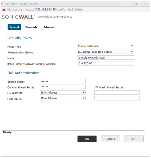
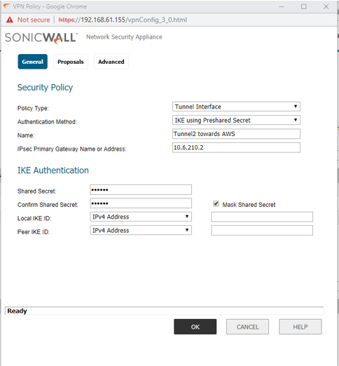
STEP 1: Go to Manage | VPN | Base Settings and click on Add. The VPN Policy window is displayed.
General tab:
Policy type: Tunnel Interface
Auth method: IKE using Preshared Secret
Local/Peer IKE ID: IPv4 Address
Note: When configuring a Numbered Tunnel Interface VPN, do not select “Allow Advance Routing” in the VPN Policy Advance tab. This option is use for Unnumbered Tunnel Interface with Advance Routing only.
NOTE: The Proposals tab must be identical on the Tunnel Interface VPNs for both appliances and should Bind with X1 and X2.
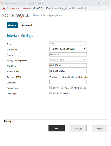
STEP 2: Configuring the Tunnel Interface.
Go to Manage |Network | Interfaces, under Add Interface field, select VPN Tunnel Interface to create the VPN tunnel interfaces on both appliances.
STEP 3: Configure BGP using CLI.
Config terminal
config# routing / Enter to Routing Module
(config-routing)# bgp / Enter to BGP module
ARS BGP> configure terminal / Enter configure mode
ARS BGP(config)> router bgp 65530/ Set up AS number on SonicWALL
ARS BGP(config-router)> neighbor 192.168.5.2 remote-as 65532 / Configure neighbor connection
ARS BGP(config-router)> neighbor 192.168.6.2 remote-as 65531 / Configure neighbor connection
ARS BGP(config-router)> neighbor 192.168.5.2 soft-reconfiguration inbound
ARS BGP(config-router)> neighbor 192.168.6.2 soft-reconfiguration inbound
ARS BGP(config-router)> network 172.16.32.0/24/ Advertise your network
STEP 4: Configure BGP using CLI and Sending the outgoing traffic via Tunnel 1 and receiving the incoming traffic via Tunnel 1.
ARS BGP(config-router)> neighbor 192.168.5.2 route-map to31 in
ARS BGP(config-router)> neighbor 192.168.6.2 route-map to32 out
SonicOS API provides an alternative to the SonicOS Command Line Interface (CLI) for configuring selected functions. SonicOS API is disabled by default in SonicOS.
To use the SonicOS API, you must enable it, either through the SonicOS Management Interface or from the CLI. SonicOS API is supported on all platforms on GEN7 and running SonicOS 6.5.4 and higher for GEN6.
Resolution
Resolution for SonicOS 7.X
This release includes significant user interface changes and many new features that are different from the SonicOS 6.5 and earlier firmware. The below resolution is for customers using SonicOS 7.X firmware.
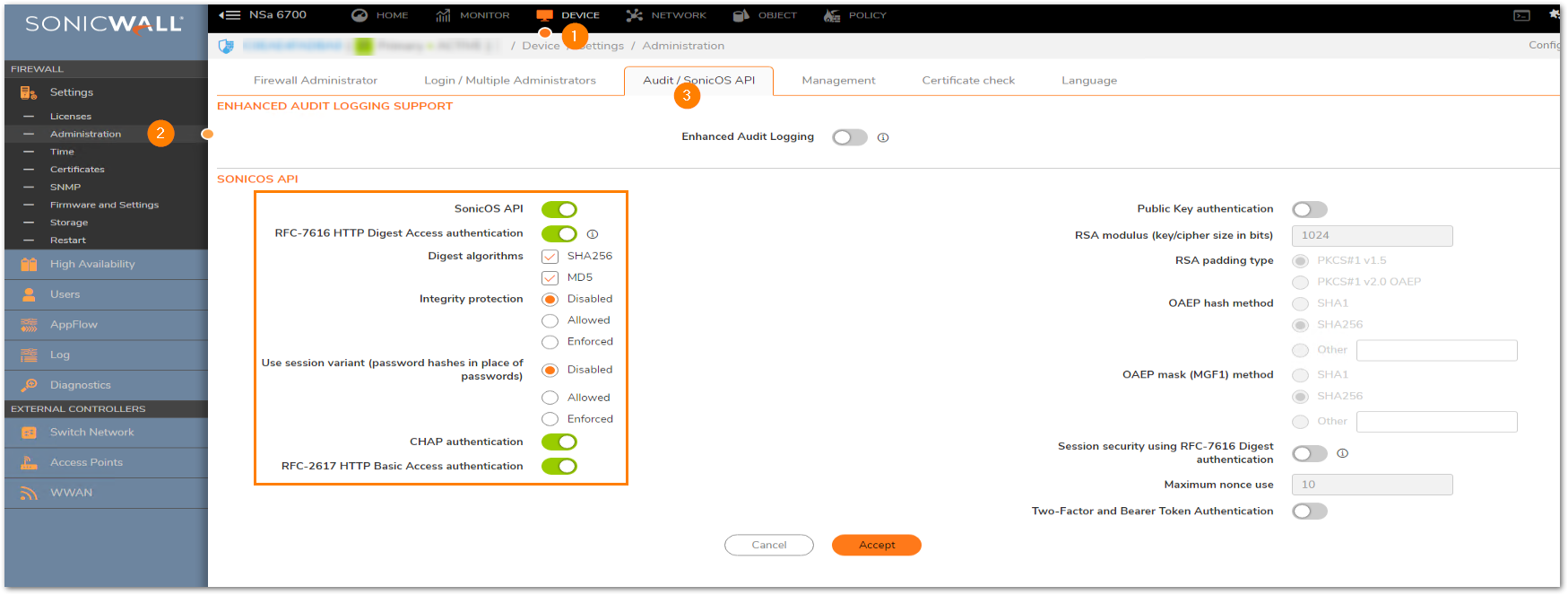
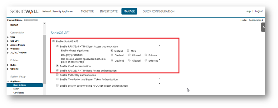
ENABLING THE API MODULE ON THE FIREWALL UI.Login to the SonicWall management UI. Navigate to Device | Settings | Administration | Audit/SonicOS API section. Enable the option ‘Enable SonicOS API’ and ‘Enable RFC-2617 HTTP Basic Access authentication’ options.
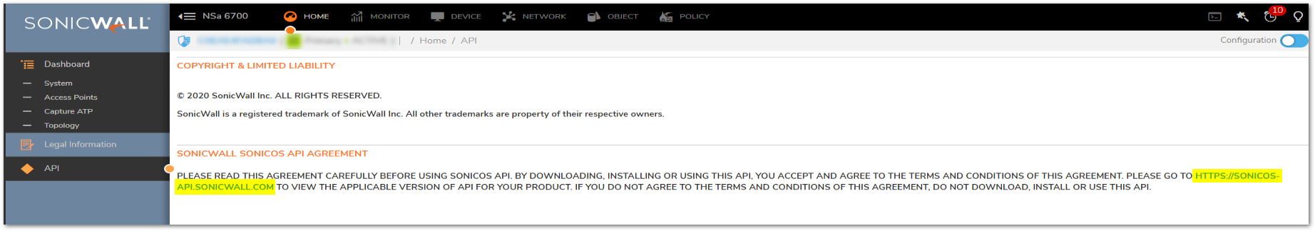
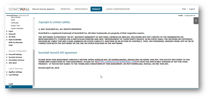
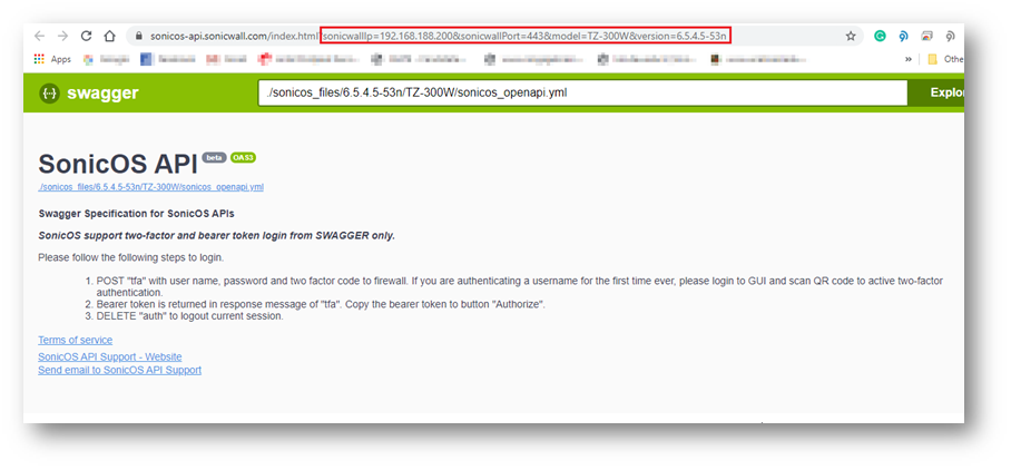
LIST OF APPLICABLE APIS:Navigate to MANAGE | API and click on the link https://SonicOS-api.sonicwall.com. Swagger will prepopulate your SonicWalls’s IP, MGMT Port, and Firmware so it can give you a list of applicable APIs.
LOGIN TO THE FIREWALL USING POSTMANThe following 3 steps need to be performed for every API request in Gen7 devices.
NOTE: https://IP-address:port/– Replace this with your SonicWall’s Public or private IP address with the right management port number (If the management port is 443, you can directly use https:// followed by the IP address without the port number too).
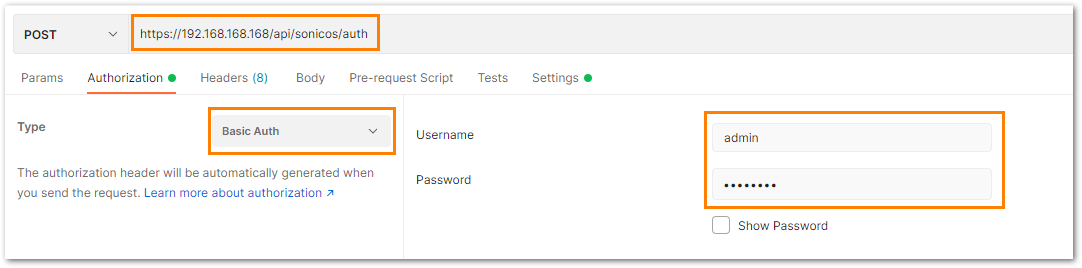
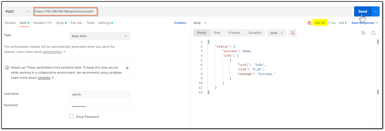
a) The HTTP method should be POST and we need to use the URL: https://192.168.168.168/api/sonicos/auth Under the authorization tab, select Basic Auth and mention the correct admin credentials.
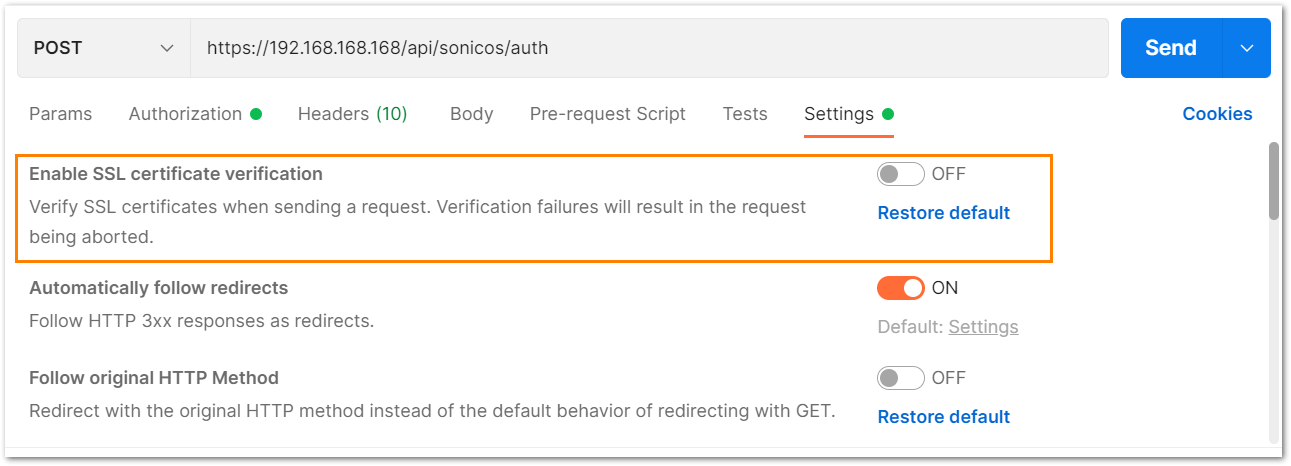
b) Under the settings tab, turn OFF the Enable SSL certificate verification if the firewall uses a self-signed certificate for management.
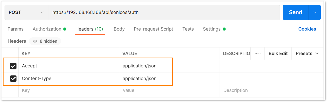
c) Under the headers tab, include application/Json as the value for keys Accept and Content-type.
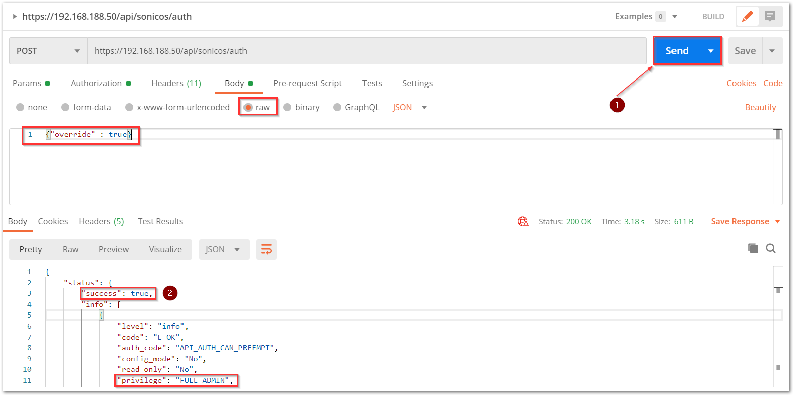
d) The Gen 7 devices are token-driven. Use the {“override” : true} under the body to override any older tokens. This is used only during login. After this, click on the Send button and then you can see the response in the section below. The response should contain a message: “success”.
e) After this, click on the Send button and then you can see the response in the section below. The response should contain a message: “success”.
cURL code: curl --location --request POST 'https://192.168.168.168/api/sonicos/auth' \--header 'Accept: application/Json' \--header 'Content-Type: application/Json' \--header 'Authorization: Basic YWRtaW46cGFzc3dvcmQ= --data-raw '{"override" : true}' Command Output should contain a string: “success”: true
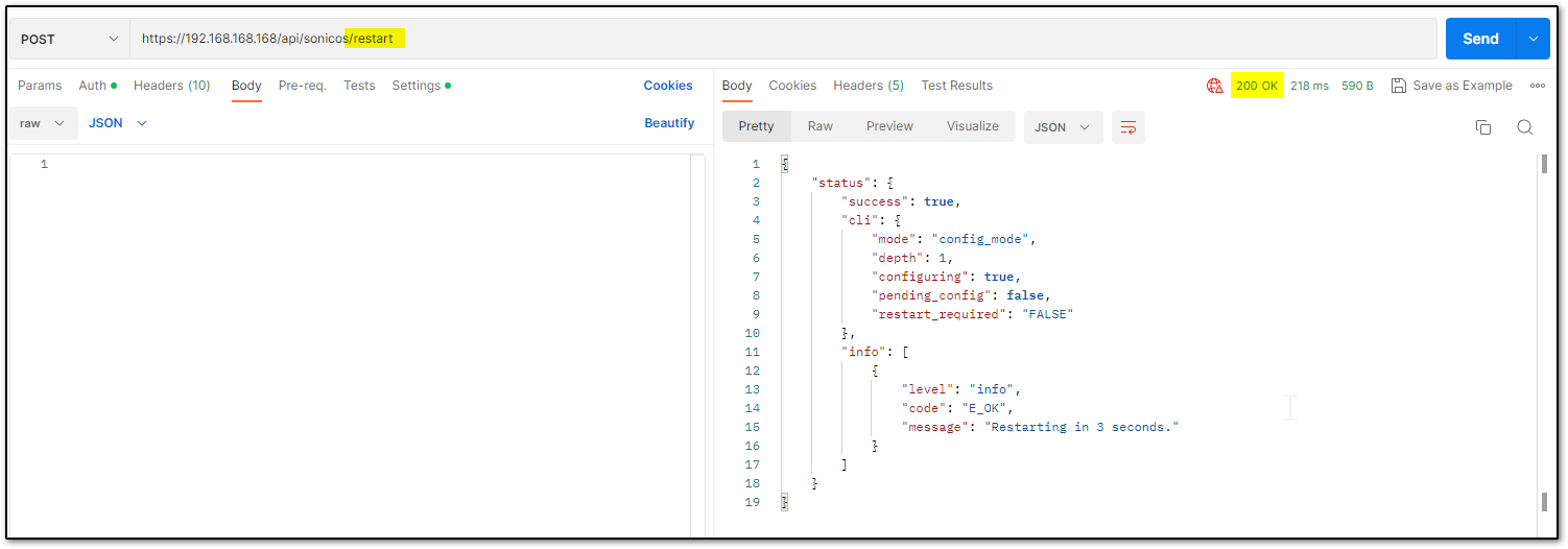
Restart command Restart can be pushed in 2 ways: now or later. There is nothing in the body of the API call as you will notice in the screenshot below.
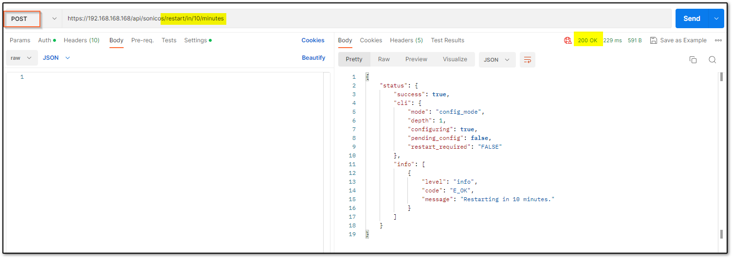
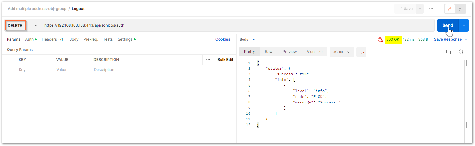
Restart in ___ minutes/hours/days/ If the plan is to restart after some time, you can schedule that. Please ensure you log out after the command since there is a waiting period. You can make other configurational changes, but it should be noted that you ‘commit’ the changes as a restart can clear off the pending configuration if not saved.
You may change the URL to suit your requirement. The number that you use should be an unsigned integer (UINT32) with values ranging from 0 to 4,294,967,295. For example, it can be made ../restart/in/2/days ../restart/in/24/hours
This release includes significant user interface changes and many new features that are different from the SonicOS 6.2 and earlier firmware. The below resolution is for customers using SonicOS 6.5 firmware.
Enabling the API Module on the firewall UI Login to the SonicWall management UI. Navigate to MANAGE | Appliance | Base Settings and scroll down to SonicOS API section. Enable the option ‘Enable SonicOS API’ and ‘Enable RFC-2617 HTTP Basic Access authentication’ options.
List of applicable APIs Navigate to MANAGE | API and click on the link https://SonicOS-api.sonicwall.com. Swagger will prepopulate your SonicWalls’s IP, MGMT Port, Firmware so it can give you a list of applicable APIs. TIP: You are free to choose Swagger, Postman, Git bash, or any application that allows API calls, if you are using a Linux based operating system you can execute cURL from the terminal. For this article I am using Git bash on Windows.
LOGIN TO THE FIREWALL USING POSTMANThe following 3 steps need to be performed for every API request in Gen7 devices.
NOTE: https://IP-address:port/– Replace this with your SonicWall’s Public or private IP address with the right management port number (If the management port is 443, you can directly use https:// followed by the IP address without the port number too).
a) The HTTP method should be POST and we need to use the URL: https://192.168.168.168/api/sonicos/auth Under the authorization tab, select Basic Auth and mention the correct admin credentials.
b) Under the settings tab, turn OFF the Enable SSL certificate verification if the firewall is using a self-signed certificate for management.
c) Under the headers tab, include application/Json as the value for keys Accept and Content-type.
d) The Gen 7 devices are token-driven. Use the {“override” : true} under the body to override any older tokens. This is used only during login. After this, click on the Send button and then you can see the response in the section below. The response should contain a message: “success”.
e) After this, click on the Send button and then you can see the response in the section below. The response should contain a message: “success”.
cURL code: curl --location --request POST 'https://192.168.168.168/api/sonicos/auth' \--header 'Accept: application/Json' \--header 'Content-Type: application/Json' \--header 'Authorization: Basic YWRtaW46cGFzc3dvcmQ= --data-raw '{"override" : true}' Command Output should contain a string: “success”: true
Restart command Restart can be pushed in 2 ways: now or later. There is nothing in the body of the API call as you will notice in the screenshot below.
Restart in ___ minutes/hours/days/ If the plan is to restart after some time, you can schedule that. Please ensure you log out after the command, if there is a waiting period. You can make other configurational changes, but it should be noted that you ‘commit’ the changes as a restart can clear off the pending configuration if not saved.
You may change the URL to suit your requirement. The number that you use should be an unsigned integer (UINT32) with values ranging from 0 to 4,294,967,295. For example, it can be made ../restart/in/2/days ../restart/in/24/hours
If you want to improve your network security and performance, learning how to set up a VLAN properly is all you need. Virtual LANs are powerful networking tools that allow you to segment your network into logical groups and isolate traffic between them.
In this post, we will go through the steps required to set up a VLAN in your network. We will configure two switches along with their interfaces and VLANs, respectively.
So, let’s dive in and learn how to set up VLANs and take your network to the next level.
Table of Contents
What is a VLAN?
Preparing for VLAN configuration
Our Lab
Network Diagram
How to set up a VLAN on a Switch?
Let’s connect to the Switch
Configure VLANs
Assign switch ports to VLANs
Configure trunk ports
Extra Configuration to Consider
What is a VLAN?
Before we go deep into learning how to set up a VLAN and provide examples, let’s understand the foundations of VLANs (or Virtual Local Area Networks).
In a nutshell, VLANs are logical groupings of devices that rely on Layer 2 addresses (MAC) for communication. VLANs are implemented to segment a physical network (or large Layer two broadcast domains) into multiple smaller logical networks (isolated broadcast domains).
Each VLAN behaves as a separate network with its own broadcast domain. VLANs help prevent broadcast storms (extreme amounts of broadcast traffic). They also help control traffic and overall improve network security and performance.
Preparing for VLAN configuration
Although VLANs are usually left for Layer 2 switches, in reality, any device (including routers and L3 switches) with switching capabilities and support of VLAN configuration should be an excellent fit for VLANs. In addition, VLANs are supported by different vendors, and since each vendor has a different OS and code, the way the VLANs are configured may slightly change.
Furthermore, you can also use specific software such as network diagramming and simulation to help you create network diagrams and test your configuration.
Our Lab
We will configure a popular Cisco (IOS-based) switch for demonstration purposes. We will use Boson NetSim (a network simulator for Cisco networking hardware and software) to run Cisco IOS simulated commands. This simulation is like you were configuring an actual Cisco switch or router.
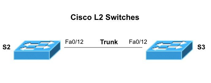
Network Diagram
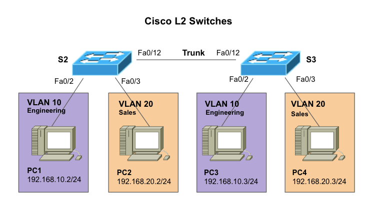
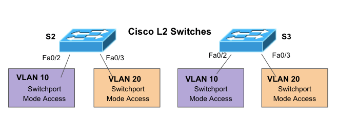
To further illustrate how to set up a VLAN, we will work on the following network diagram. We will configure two VLANs in two different switches. We will then configure each port on the switches connected to a PC. We will then proceed to configure the trunk port, which is vital for VLAN traffic.
Network diagram details
S2 and S3 (Switch 2 and Switch 3) – Two Cisco L2 Switches connecting PCs at different VLANs (VLAN 10 and VLAN 20) via Fast Ethernet interfaces.
VLANs 10 and VLAN20. These VLANs configured in L2 switches (S2 and S3) create a logical grouping of PCs within the network. In addition, each VLAN gets a name, VLAN 10 (Engineering) and VLAN 20 (Sales).
PCs. PC1, PC2, PC3, and PC4 are each connected to a specific L2 switch.
How to set up a VLAN on a Switch?
So now that you know the VLAN configuration we will be using, including the number of switches, VLAN ID, VLAN name, and the devices or ports that will be part of the configuration, let’s start setting up the VLANs.
Note:VLAN configuration is just a piece of the puzzle. Switches also need proper interface configuration, authentication, access, etc. To learn how to correctly connect and configure everything else, follow the step-by-step guide on how to configure a Cisco Switch.
a. Let’s connect to the switch
Inspect your hardware and find the console port. This port is usually located on the back of your Cisco switch. You can connect to the switch’s “console port” using a console cable (or rollover). Connect one end of the console cable to the switch’s console port and the other to your computer’s serial port.
Note: Obviously, not all modern computers have serial ports. Some modern switches come with a Mini USB port or AUX port to help with this. But if your hardware doesn’t have these ports, you can also connect to the switch port using special cables like an RJ-45 rollover cable, a Serial DB9-to-RJ-45 console cable, or a serial-to-USB adapter.
Depending on your switch’s model, you can configure it via Command Line Interface (CLI) or Graphical User Interface (GUI). We will connect to the most popular user interface: The IOS-based CLI.
To connect to your switch’s IOS-based CLI, you must use a terminal emulator on your computer, such as PuTTY or SecureCRT.
You’ll need to configure the terminal emulator to use the correct serial port and set the baud rate to 9600. Learn how to properly set these parameters in the Cisco switching configuration guide.
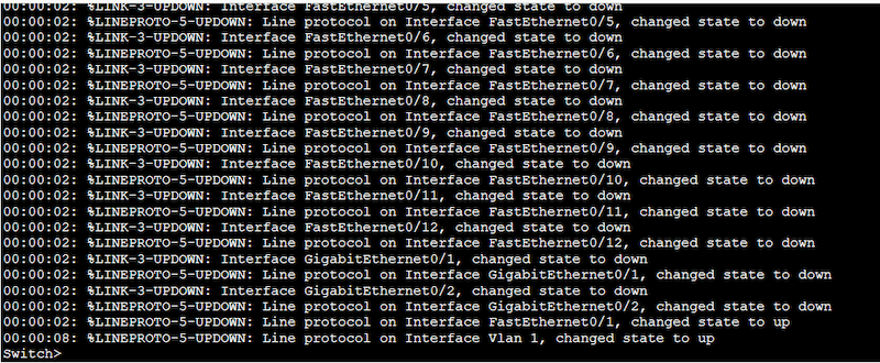
In the terminal emulator, press Enter to activate the console session. The Cisco switch should display a prompt asking for a username and password.
Enter your username and password to log in to the switch.
b. Configure VLANs
According to our previously shown network diagram, we will need two VLANs; VLAN 10 and VLAN 20.
To configure Layer 2 switches, you need to enter the privileged EXEC mode by typing “enable” and entering the password (if necessary).
Enter the configuration mode by typing “configure terminal.”
Create the VLAN with “vlan <vlan ID>” (e.g., “vlan 10”).
Name the VLAN by typing “name <vlan name>” (e.g., “name Sales”).
Repeat these two steps for each VLAN you want to create.
Configuration on Switch 2 (S2)
S2# configure terminal
S2(config)# vlan 10
S2(config-vlan)# name Engineering
S2(config-vlan)# end
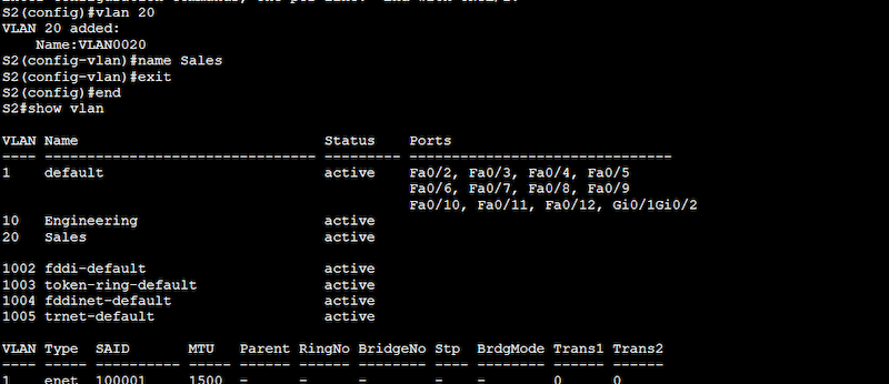
S2# configure terminal
S2(config)# vlan 20
S2(config-vlan)# name Sales
S2(config-vlan)# end
Use the “show vlan” command to see the configured VLANs. From the output below, you’ll notice that the two new VLANs 10 (Engineering) and 20 (Sales) are indeed configured and active but not yet assigned to any port.
Configuration on Switch 3 (S3)
S3# configure terminal
S3(config)# vlan 10
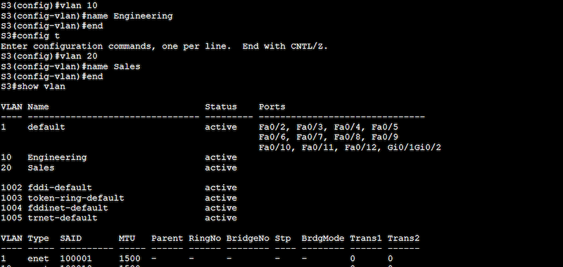
S3(config-vlan)# name Engineering
S3(config-vlan)# end
S3# configure terminal
S3(config)# vlan 20
S3(config-vlan)# name Sales
S3(config-vlan)# end
Note: From the output above, you might have noticed VLAN 1 (default), which is currently active and is assigned to all the ports in the switch. This VLAN, also known as native VLAN, is the default VLAN on most Cisco switches. It is used for untagged traffic on a trunk port. This means that all traffic that is not explicitly tagged with VLAN information will be sent to this default VLAN.
Now, let’s remove those VLAN 1 tags from interfaces Fa0/2 and Fa0/3. Or in simple words let’s assign the ports to our newly created VLANs.
c. Assign switch ports to VLANs
In the previous section, we created our VLANs; now, we must assign the appropriate switch ports to the correct VLANs. The proper steps to assign switch ports to VLANs are as follows:
Enter configuration mode. Remember to run these commands under the configuration mode (configure terminal).
Assign ports to the VLANs by typing “interface <interface ID>” (e.g., “interface GigabitEthernet0/1”).
Configure the port as an access port by typing “switchport mode access”
Assign the port to a VLAN by typing “switchport access vlan <vlan ID>” (e.g., “switchport access vlan 10”).
Repeat these steps for each port you want to assign to a VLAN.
Let’s refer to a section of our network diagram
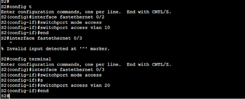
Configuration on Switch 2 (S2)
S2(config)# interface fastethernet 0/2
S2(config-if)# switchport mode access
S2(config-if)# switchport access vlan 10
S2(config)# interface fastethernet 0/3
S2(config-if)# switchport mode access
S2(config-if)# switchport access vlan 20
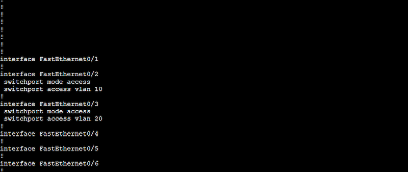
Use the “show running-configuration” to see the new configuration taking effect on the interfaces.
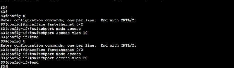
Configuration on Switch 3 (S3)
S3(config)# interface fastethernet 0/2
S3(config-if)# switchport mode access
S3(config-if)# switchport access vlan 10
S3(config)# interface fastethernet 0/3
S3(config-if)# switchport mode access
S3(config-if)# switchport access vlan 20
A “show running-configuration” can show you our configuration results.
d. Configure trunk ports
Trunk ports are a type of switch port mode (just like access) that perform essential tasks like carrying traffic for multiple VLANs between switches, tagging VLAN traffic, supporting VLAN management, increasing bandwidth efficiency, and allowing inter-VLAN routing.
If we didn’t configure trunk ports between our switches, the PCs couldn’t talk to each other on different switches, even if they were on the same VLAN.
Here’s a step by step to configuring trunk ports
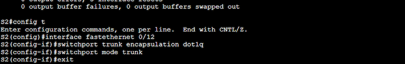
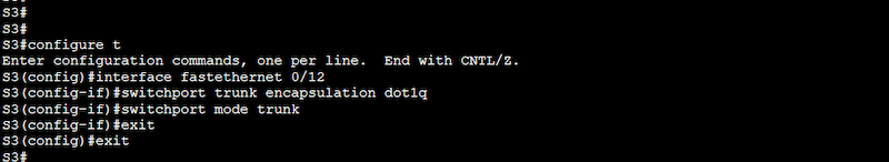
Configure a trunk port to carry traffic between VLANs by typing “interface <interface ID>” (e.g., “interface FastEthernet0/12”).
Set the trunk encapsulation method (dot1q). The IEEE 802.1Q (dot1q) trunk encapsulation method is the standard tagging Ethernet frames with VLAN information.
Configure the port as a trunk port by typing “switchport mode trunk”.
Repeat the steps for each trunk port you want to configure.
Note (on redundant trunk links): To keep our article simple, we will configure one trunk link. However, keep in mind that any good network design (including trunk links) would need redundancy. One trunk link between switches is not an optimal redundant solution for networks on production. To add redundancy, we recommend using EtherChannel to bundle physical links together and configure the logical link as a trunk port. You can also use Spanning Tree Protocol (STP) by using the “spanning-tree portfast trunk” command.
Note: You can use different types of trunk encapsulation such as dot1q and ISL, just make sure both ends match the type of encapsulation.
Extra Configuration to Consider
Once you finish with VLAN and trunk configuration, remember to test VLAN connectivity between PCs, you can do this by configuring the proper IP addressing and doing a simple ping. Below are other key configurations related to your new VLANs that you might want to consider.
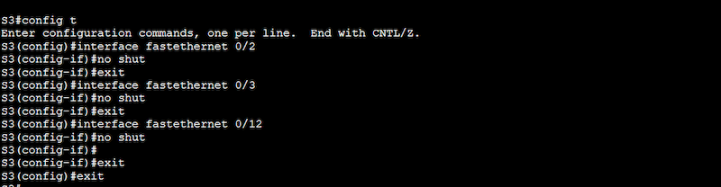
a. Ensure all your interfaces are up and running
To ensure that your interfaces are not administratively down, issue a “no shutdown” (or ‘no shut’) command on all those newly configured interfaces. Additionally, you can also use the “show interfaces” to see the status of all the interfaces.
b. (Optional) enable inter-VLAN
VLANs, as discussed earlier, separate broadcast domains (Layer 2) — they do not know how to route IP traffic because Layer 2 devices like switches can’t accept IP address configuration on their interfaces. To allow inter-VLAN communication (PCs on one VLAN communicate with PCs on another VLAN), you would need to use a Layer 3 device (a router or L3 switch) to route traffic.
There are three ways to implement inter-VLAN routing: an L3 router with multiple Ethernet interfaces, an L3 router with one router interface using subinterfaces (known as Router-On-a-Stick), and an L3 switch with SVI.
We will show a step-by-step on how to configure Router-On-a-Stick for inter-VLAN communications.
Connect the router to one switch via a trunk port.
Configure subinterfaces on the router for each VLAN (10 and 20 in our example). To configure subinterfaces, use the “interface” command followed by the VLAN number with a period and a subinterface number (e.g., “interface FastEthernet0/0.10” for VLAN 10). For example, to configure subinterfaces for VLANs 10 and 20, you would use the following commands:
> router(config-subif)# ip address 192.168.20.1 255.255.255.0
Configure a default route on the router using the “ip route” command. This is a default route to the Internet through a gateway at IP address 192.168.1.1. For example:
> router(config)# ip route 0.0.0.0 0.0.0.0 192.168.1.1
c. Configure DHCP Server
To automatically assign IP addresses to devices inside the VLANs, you will need to configure a DHCP server. Follow these steps:
The DHCP server should also be connected to the VLAN.
Configure the DHCP server to provide IP addresses to devices in the VLAN.
Configure the router to forward DHCP requests to the DHCP server by typing “ip helper-address <ip address>” (e.g., “ip helper-address 192.168.10.2”).
Final Words
By following the steps outlined in this post, you can easily set up a VLAN on your switch and effectively segment your network. Keep in mind to thoroughly test your VLAN configuration and consider additional configuration options to optimize your network for your specific needs.
With proper setup and configuration, VLANs can greatly enhance your network’s capabilities and 10x increase its performance and security.


 On the Settings tab of the LDAP Configuration window, configure the following fields.
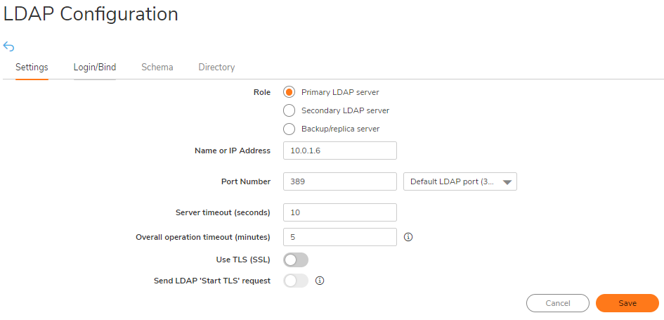
 NOTE: Performing tests on this page applies any changes that have been made.
 CAUTION: It is not recommended to do this change on a Production Environment because this changes are instant and can affect all the computers on the LAN. So it is best to schedule a downtime before proceeding further.