Windows services are often useful since they are background applications that don’t require any attention from the end-user. The service launches upon startup, without any intervention from the user. The service is a direct replacement for running the Network application manually (via the icon or a scheduled task), so there is no need to run the UniFi Network application if it is being run as a Windows service.
This article describes how to set up the UniFi Network application to run as a Windows service, and how to update it when it’s running this way.NOTES & REQUIREMENTS:
Applicable to the latest UniFi application versions for Windows.
This article applies to UniFi applications that are installed on Windows Desktop (Windows 10) and not Windows Server versions.
It is recommended to only install the x64 version of Java 8 for the UniFi Cloud Access Portal to work properly.
Make sure to allow the ports used by the UniFi application through the Windows Firewall. See the UniFi – Ports Used article for more information.
How to set up the UniFi Network application as a Windows Service
ATTENTION: It is recommended to only install the x64 version of Java 8 for the UniFi Cloud Access Portal to work properly. However, older versions of the Network application may require both x64 and x86 Java to be installed on a Windows x64 system.
1. Close any instances of the UniFi Network application on the computer. If the UniFi Network application was just installed, make sure to open the application manually at least once, or let it run at the end of the wizard. Once you see the message UniFi Network application (a.b.c) started, the application may be closed.CLI:Open an administrative Windows Command Prompt (CMD) window.
2. Change the directory to the location of UniFi installation.
cd "%UserProfile%\Ubiquiti UniFi\"
Click to copy
3. Once in the root of the UniFi folder, run the following command to install the UniFi Network application service:
java -jar lib\ace.jar installsvc
Click to copy
4. Wait for the installation to complete, indicated by the Complete Installation log message.
5. Start the service with the command below:
java -jar lib\ace.jar startsvc
Click to copy
6. Open a browser and navigate to the application’s IP address or https://localhost:8443.
How to upgrade a UniFi Network application that is running as a Windows Service
1. Create a backup of your Network application.CLI:Open an administrative Windows Command Prompt (CMD) window.
2. Change the directory to the location of UniFi installation.
cd "%UserProfile%\Ubiquiti UniFi\"
Click to copy
3. Once in the root of the UniFi folder, issue the following to uninstall the Network application service:
java -jar lib\ace.jar uninstallsvc
Click to copy
4. Wait for the service uninstall process to complete.
5. Launch the Network application and update it through the Settings section. Alternatively, download the latest installation file from the Downloads section.
6. Repeat the steps from the section above after the new Network application version is installed.
This article describes how to perform advanced configurations on the UniFi Security Gateway (USG and USG-PRO-4) using the config.gateway.json file. This article is not applicable to the UniFi Dream Machine models. The UDM line does not support configurations done outside of the UniFi Network application.NOTES & REQUIREMENTS:
Ubiquiti Support cannot assist in the creation of the config.gateway.json file nor will assistance be provided for command line configuration. If assistance is required, feel free to visit our Community to create a topic and ask for help with your desired configuration.
This article covers advanced configuration, and should only be used by advanced users.
The config.gateway.json is a file that sits in the UniFi Network application filesystem and allows custom changes to the USG that aren’t available in the web GUI. Some possible customizations will be: configuring site-to-site VPNs with hostnames, policy routing certain traffic out WAN2, or even adding multiple IP addresses on an interface. These features don’t exist in the UniFi Network application yet, so the config.gateway.json file will supplement those features until they’re available in the GUI.
When making customizations via the config.gateway.json file, it is best to enter only the customizations that can’t be performed via the Network application. If the formatting is incorrect, a provisioning loop will be triggered on the USG, and a reboot will take place once the USG comes out of the provisioning loop. At this point the config.gateway.json file could be corrected or removed to correct this.WARNING:Some users may find they can get away with using the full config, but this is not recommended as it will most likely cause issues down the road. A provisioning loop might take place when a setting is changed in the Network application that conflicts with a setting in the config.gateway.json file.
Creating the config.gateway.json File
By default, the config.gateway.json file doesn’t exist, it has to be created in order to use it.
1. Create a new file using a text editor such as TextEdit or Notepad++.
2. The structure of a json file is just as important as the words themselves. Incorrect placement of brackets, indentations, line breaks or any other structural element will make the json file invalid. It is recommended to run the text through a json validator in order to verify it has the correct syntax. The JSON Formatter website is one example of the many options of json validators you’ll find online.
3. Once the contents of the file has been validated, save it by naming it config.gateway.json and placing it under the <unifi_base>/data/sites/site_IDdirectory stored on the Network application. User Tip:Depending on your operating system, placing the file under this directory might be as simple as drag and drop, or using a FTP server might be necessary. The config.gateway.json file must have unifi:unifi as the owner and group permissions. You can check to verify with ls -l <unifi_base>/data/sites/site_ID. To change it, once you’re in the site directory, use the command: chown unifi:unifi config.gateway.json
The location <unifi_base> will vary from one operating system to another. See this article for more information. The site_ID can be seen in the URL of your browser when on the Network application. The original site is named “default”, and every site that is created will be assigned a random string. For example, this is what would be seen in the URL bar when inside the dashboard page of a site:
In the above case, the random string ceb1m27d is the folder name that shall be used under <unifi_base>/data/sites/. Therefore, theconfig.gateway.json should be placed inside <unifi_base>/data/sites/ceb1m27d/.User Tips:
On Cloud Key install the path for the .json file is: /srv/unifi/data/sites/[site name/default]/
On an Ubuntu install the path for the .json file is: /usr/lib/unifi/data/sites/[site name/default]/
Editing the config.gateway.json File
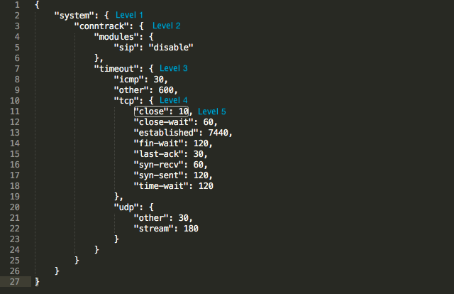
Before customizing firewall or NAT rules, take note of the rule numbers used in the UniFi Network application under Settings > Routing & Firewall > Firewall. Default firewall rules start at either 3001 or 6001, and NAT rules will also start at 6001 (which don’t overlap with firewall rules). The custom rules created in the config.gateway.json cannot have duplicate rule numbers with the existing rules in the USG, or there will be a provisioning loop. It is recommended to put custom rules before the existing ruleset, as the lower number will win between two matching rules.NOTE: When editing thiscustom json file, it is not necessary to include everything. You must only include the complete “path” to the items you have edited, anything outside of the path can be omitted. Think of each node in the json file as a folder that is nested within other folders (except for the level 1 folder which is our main section). The folder path that takes you from level 1 all the way down to the item you will be configuring must be present in the json file. See this example where we want to edit “close”, which has the following path: system > conntrack > timeout > tcp > close.
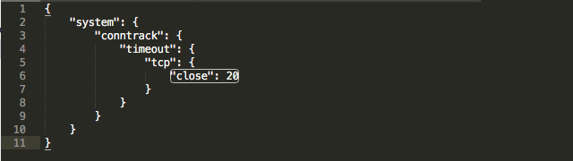
Notice that in level 3 “modules” is also present along with “timeout”, but we will not include it in the json file because it is not part of the path to “close”. Same with the other items in level 5 under “tcp”. They do not need to appear in the config.gateway.json file because they are not part of the path. A successful change then, in the configuration of “close” from 10 to 20 would look like this:
The following is an example of how a DNAT rule is created for DNS configured using EdgeOS formatting:
1. Connect to the USG via SSH, and issue the following commands:
configure
set service nat rule 1 type destination
set service nat rule 1 inbound-interface eth0
set service nat rule 1 protocol tcp_udp
set service nat rule 1 destination port 53
set service nat rule 1 inside-address address 10.0.0.1
set service nat rule 1 inside-address port 53
commit;save;exit
2. Next is displaying the config. The following command displays the entire config in a JSON format:
mca-ctrl -t dump-cfg
The config can also be exported if preferred. The following example exports the output to the config.txt:
mca-ctrl -t dump-cfg > config.txt
3. Find the appropriate section with the custom changes in the config output, for our example above it would be the following:
4. Above is the custom rule, but it’s missing all the closing brackets (}) at the end to make it correct. If you look at the config output from the start, there is a certain format that is required for the file to be read correctly. Each node in a section must be separated by a comma (,), and it section must begin with an opening bracket ({) and finish with a closing one (}). Follow the existing format carefully. If the above rule is the only change in the config.gateway.json, you would edit it to look like so:
5. If there are multiple sections to add, say Firewall, Service, VPN, the closing bracket for that section would be followed by a comma (},), before starting the next section. You can see these formatting details in the example below.
The DNAT rule # ranges are from 1-4999, and the Source/Masquerade rule numbers are from 5000-9999. If you wanted to add a port forward (DNAT) in the config.gateway.json for WAN2 in a multiWAN (load-balance) setup, this is what the config.gateway.json would look like with only this particular NAT rule:
And if we were to add a VPN with hostnames to the file, the config.gateway.json would look like the one below. Notice the opening and closing brackets, as well as the bracket with comma before starting with the "vpn" section:
It’s recommended to validate the code once finished creating the config.gateway.json. There are a number of free options out there, jsonlint.com is used by the Ubiquiti support team quite often.
After adding the config.gateway.json to the UniFi Network site of your choosing, you can test it by running a “force provision” to the USG in UniFi Devices > select the USG > Config > Manage Device > Force provision. This will take a while to provision (30 seconds to 3 minutes), and if it stays in provisioning longer than that, there may be a formatting error in the config.gateway.json, and you are experiencing the provisioning loop that was mentioned earlier. You can check server.log in the application and search for commit error. You can usually find what went wrong with the provisioning of the newly customized configuration in the log files. Find information about that here.User Tip:An easy way to test the validity of the json file is: python -m json.tool config.gateway.json
Deleting Changes or Reverting to Previous State
To remove a certain advanced configuration, just delete the section pertinent to that configuration in the config.gateway.json file. To completely remove all advanced configurations created in the config.gateway.json file, delete the file or rename it. This will void all manual changes. The USG will be provisioned with the current config contained within the UniFi Network application.
A best practice when editing an already working config.gateway.json file is to create a backup. If you need to add additional changes to the config.gateway.json file, rename the current file to config.gateway.json.old, essentially creating a backup, and copy all the existing and new changes into a new file named config.gateway.json. This way, if there happens to be any mistakes resulting in a “commit” error or provisioning loop, you can delete config.gateway.json, and try again starting from config.gateway.json.old.
This article describes what the system.properties file is used for and how to edit it.NOTES & REQUIREMENTS:This article includes some advanced configurations that should only be performed by advanced users. Advanced configurations are not supported by our Support team. The Community is the best place to find experts to guide you with advanced configurations.
The system.propertiesfile, found within <unifi.base> in the data folder, is the file inside the UniFi server installation directory, which defines system-wide parameters for the UniFi Network application. Here are just a few notable examples of supported configuration changes for UniFi Network application made in the system.properties file:
Manual override of the Application IP Interface (the address to which Devices send inform packets).
Advanced Database adjustments.
Port Assignments, for purposes of the UniFi Network application communicating with Managed Devices, redirecting Guest Portal traffic, etc.
WARNING:Before editing the system.properties file, remember to create a backup of your system and download it to a safe place. It is also necessary to stop the application before performing any change in the file to avoid errors after changes are made.
Thesystem.properties file can be edited directly via any text editor. Keep in mind that lines preceded by hash-tags (#) exist as comments and are non-operational. Make edits at the bottom of the file. After changing this file, you’ll need to manually trigger provisioning on each site in order to make these effective.NOTE:The system.properties file is created when UniFi Network runs successfully. If you cannot find the file within the <unifi_base>, create it by running the UniFi Network application .
Manually Specify the IP Interface for UniFi Network Application Communication
If a UniFi OS Console (or device hosting the application) has multiple IP interfaces, the following configuration can manually set the exact IP interface that adopted APs should communicate to the Network application:
system_ip=a.b.c.d # the IP devices should be talking to for inform
Advanced Database Configuration
Below are advanced database configurations that most users will never need. Note: We do not perform tests on these configurations, they are enabled for the convenience of database experts. One possible usage scenario is where few people run their application on a NAS, which has a smaller footprint than a normal server, hence there’s a need to reduce the required resources.
The configuration below is used to facilitate UniFi Network application installation. Again, most users will never need to set this. When the is_default is set to true, the application will start with factory default configuration. For normal, everyday users, an uninstallation and then fresh re-installation is recommended over this.
is_default=true
From the UniFi Network application you can configure the autobackup frequency, amount of backups to store, time of backup, etc. At the time of writing this, you cannot change the storage location via the application. We do have a variable in the system.properties if you wish to change the storage location. Currently, the default points to:
1. For Cloud Key: /data/autobackup (where SD card is mounted as /data by default) 2. For software installs: {data.dir}/backup/autobackup
autobackup.dir=/some/path
The UAP-AC-EDU is recommended to be managed from a local application. The current communication from the EDU mobile app relays from app to Network application to EDU. If the mobile device is remote to the EDU, then you just need to open the appropriate ports. If the UniFi Network application is remote to the EDUs, then you need to add the following line to system.properties.
stream.playback.url.type=inform
(5.5.15+/5.6.7+) We’ve added HSTS support to the application. Do note that it is default disabled. This should only be enabled if you know what you’re doing with it. This will only ever be a system.properties value so it can be easily disabled in case of issues. If you run into issues, you likely will need to clear your browser’s cache after disabling this and restarting the service. To enable HSTS support add the following:
unifi.https.hsts=true
unifi.https.hsts.max_age=31536000
unifi.https.hsts.preload=false
unifi.https.hsts.subdomain=false
NOTE: Currently no characters after the custom line(s) are allowed. This includes spaces, pound/sharp signs/comments, etc.
SMTP Related Settings
By default, SMTPS validates certificates and will reject self-signed or untrusted certificates. If your mail server uses an untrusted certificate, you must disable certificate verification with the following: smtp.checkserveridentity=false
Starting with UniFi Network version 6.1, STARTTLS is opportunistically enabled by default; e.g. will be used if the server announces support for it, and will require a trusted certificate. If using a self-signed or untrusted certificate, you must disable STARTTLS by setting the following: smtp.starttls_enabled=false
This only controls whether STARTTLS will be used if the server supports it. To force its use, see: starttls_required
With UniFi Network version 6.1 and newer, STARTTLS is opportunistically enabled by default, but only required if using port 587. This behavior can be overridden by setting smtp.starttls_required=true to force the use of STARTTLS on ports other than 587, or to make STARTTLS optional on port 587, set it to false.
If smtp.starttls_enabled=false is set, the starttls_required value has no impact.
User Tips & Notes
If receiving error, it’s possible there are hash tags (#) present in front of commands. Hash tags indicate comments, and will make commands not work until hash tag is removed.
If you want to reduce the logging frequency on your RPi UniFi Network application, see this Community thread. ATTENTION:Without logs, it is impossible to receive appropriate support. Use this tip under your own discretion. See how to extract logs in our UniFi – How to View Log Files article.
If you cannot find the system.properties file, it might not have been created yet. This file is created once the UniFi app runs successfully. If you need to change port numbers because of a port clash, it doesn’t count as a successful launch and does not create the file, so you can’t alter the port numbers to avoid the clash.
This article shows what UDP and TCP ports are used by the UniFi Network application by default. The information applies to both Network applications hosted on UniFi OS Consoles, such as UniFi Cloud Key (UCK-G2, UCK-G2-PLUS, and UC-CK) or UniFi Dream Machine (UDM or UDM-Pro), as well as self-hosted Network applications.
Note: Make sure to always update your Network application to the latest version.
Port used for device and application communication.
TCP
443
Port used for application GUI/API as seen in a web browser.Applications hosted on a UniFi OS Console
TCP
8443
Port used for application GUI/API as seen in a web browser.Applications hosted on Windows/macOS/Linux
TCP
8880
Port used for HTTP portal redirection.
TCP
8843
Port used for HTTPS portal redirection.
TCP
6789
Port used for UniFi mobile speed test.
TCP
27117
Port used for local-bound database communication.
UDP
5656-5699
Ports used by AP-EDU broadcasting.
UDP
10001
Port used for device discovery.
UDP
1900
Port used for “Make application discoverable on L2 network” in the UniFi Network settings.
Note: Although TCP 22 is not one of the ports UniFi Network operates on by default, it is worth mentioning in this article since it is the port used when UniFi devices or the Network application is accessed via SSH.
Ingress Ports required for L3 management over the internet
Note: These ports need to be open at the gateway/firewall as well as on the UniFi Network application host. This would be achieved by creating port forwards on the gateway/firewall where the application is hosted.
Protocol
Port number
Usage
UDP
3478
Port used for STUN.
TCP
8080
Port used for device and application communication.
TCP
443
Port used for application GUI/API as seen in a web browser.Applications hosted on a UniFi OS Console
TCP
8443
Port used for application GUI/API as seen in a web browser.Applications hosted on Windows/macOS/Linux
TCP
8843
Port used for HTTPS portal redirection.
TCP
6789
Port used for UniFi mobile speed test.
Egress Ports required for UniFi Remote Access
Note: In most cases, these ports will be open and unrestricted by default.
Protocol
Port number
Usage
UDP
3478
Port used for STUN.
TCP/UDP
443
Port used for Remote Access service.
TCP
8883
Port used for Remote Access service.
Changing Default Ports
Changing default port assignments can only be done on self-hosted Network applications (Windows/macOS/Linux). This can be accomplished as follows:
1. Close any instances of the UniFi Network application.
2. Modify the system.properties file, which can be found in the directory <unifi_base>/data/system.properties.
For example, if port 8081 was in use and port 8089 was open, you could change it by modifying unifi.shutdown.port=8081 to unifi.shutdown.port=8089
3. Restart the UniFi Network application.
Note: Make sure there are no leading or trailing spaces, comments, or other characters like hash tags (#) on any custom lines. Otherwise, UniFi Network will ignore the customizations.
This article describes the different statuses a UniFi Access Point might be ascribed by the UniFi Network application within the UniFiDevices section.
Device Status
Description
Connected
The UAP is physically wired to the network by ethernet cable. The UAP is in a connected state, able to service WLAN stations. Currently, no updates/changes to configuration are being run on the UAP.
Connected (Wireless)
The UAP is wirelessly uplinked to a physically wired AP.
Connected (100 FDX)
The UAP is physically wired to the network at 100 Mbps in full-duplex mode. This will appear when a UAP is connected but not at the ideal connection rate. FDX stands for Full Duplex. It may appear as 10/100/1000, HDX or FDX.
Connected (Disabled)
The UAP has been disabled in the UniFi Network application. Properties > Manage Device > Disable this Device. It will be excluded from the dashboard status, and its LED and WLAN will be turned off.
Connected (Limited)
This will appear when a UAP is connected and can reach the UniFi Network application, but is unable to reach either the gateway or the custom IP defined for the uplink connectivity monitor. In this state downlink UAPs (wireless UAPs) will become Isolated.
Provisioning
The UAP is in a connected state, however it is applying updates/changes to the configuration, and will shortly reboot (temporarily disconnecting WLAN stations), and return back online.
Restarting
After clicking on the Restart button in the Actions column, the device will restart.
Adopting
Device is adopting normally.
Pending Adoption
The UAP has been detected by the UniFi Network application, but is not adopted yet. Click on the Adopt button to do so.
Pending Adoption (Update Required)
Devices with firmware that are too old for UniFi Network application will see this when attempting to adopt. Clicking Update will upgrade the Device to the latest stable firmware release and adopt the Device to the application.
Heartbeat Missed
The UniFi Network application did not receive a reply at the dynamically scheduled interval. This will appear before “Disconnected,” usually about 30-45 seconds after missing the interval. This is usually seen when configuring a wireless uplink, if state does not change to connected after a while something went wrong. See this article for wireless uplink instructions.
Disconnected
The adopted UAP is now in a disconnected state, meaning the UniFi Network application does not have connectivity to the access point (check cables, network settings, and changes to topology).
Isolated
The adopted UAP is unable to reach the gateway and is awaiting a nearby, wired UAP, which is already managed by the UniFi Network application in order to establish “wireless uplink.” See this article for wireless uplink instructions.
Managed by Other
A UAP is located on the same network as the UniFi Network application, but is already bound to another UniFi Network application. Providing the username/password to the UAP will unbind the UAP from the existing Network application and begin adoption in current application. See this article: UniFi – Advanced Adoption of a “Managed By Other” Device.
Upgrading
The UAP is upgrading and should not be disconnected. This should be accompanied by the AP’s LED flashing. (See what the different LED combinations mean in this article).
directory for Linux is mentioned below as it is the consistent folder location on the officially supported distros. It is the same whether you install the UniFi Network application on your own installation of Debian or Ubuntu, or a UniFi Cloud Key. Depending on the platform being used, and how it is configured, there will be other locations, but no matter what, on the supported distros, /usr/lib/unifi/logs will always contain the files.
There are three locations where you can view log files related to UniFi devices and the Network application: /var/log/messages, server.log, and mongod.log. See below what you will find in each.
1. UniFi Dream Machines
/var/log/messages
2. UniFi AP: contains info local to UniFi Access Points, like 802.11 info
/var/log/messages
3. UniFi Switch: contains info local to the switch, like port link state changes, spanning tree events, etc.
/var/log/messages
4. UniFi Security Gateway: contains USG’s general logging.
/var/log/messages
5. UniFi Network application:
Contains information about the Network application, communication with UAPs, etc:
server.log
Contains information about UniFi software local to Network application installed on a PC.
mongod.log
How to View Log Files: UniFi APs and Switches
To view log files under UAP and USW:
1. Connect to UAP or USW via SSH. 2. Type:
cat /var/log/messages
3. View output.
To view the live logs, with output updating in your SSH session as new logs are appended, run the following instead of the above cat command.
tail -f /var/log/messages
How to View Log Files: UniFi Security Gateways
To view log files under a USG:
1. Connect to the USG via SSH. 2. In the EdgeOS CLI, the log can be viewed by running the following commands:
General Logging
show log
IPsec VPN Logging
show vpn log
FreeRADIUS Logging
sudo cat /var/log/freeradius/radius.log
DNSmasq Logging
sudo cat /var/log/dnsmasq.log
IPS/IDS Engine Logging
sudo cat /var/log/suricata/suricata.log
3. View live logging.
To view the live logs, with output updating in your SSH session as new logs are appended, run the following instead of the cat command above.
tail -f /var/log/messages
User Tip:If a user would like to only get the last number of lines the tail utility can be used. The command below will output the last 10 lines of the radius.log file.
sudo tail -n 10 /var/log/freeradius/radius.log
NOTE:Firewall logs aren’t in the UI yet. Please see this Community post for more details.
How to Download Encrypted Log Files from the Network Application
The Network application also allows users to download log files to share with Ubiquiti support, but these logs are encrypted (for security reasons), so as the user, you wouldn’t be able to view the logs. For viewing, we continue to suggest all the options described above. It is important to note that this support file does not include device logs.
In the Network application, go to Settings > System Settings > Maintenance > Support information, and click Download Logs.
For Network applications not hosted on UniFi OS Consoles, you can find the logs in the following locations:
New Microsoft Graph APIs released today in public preview allow developers and IT professionals to manage Windows 10 updates and expedite Windows 10 security updates in enterprise environments.
Microsoft Graph is an API platform that helps developers create apps capable of accessing Microsoft 365, Windows 10, and Enterprise Mobility + Security data.
Access to deployment service update management capabilities
“By connecting deployment service capabilities with Microsoft Graph, app developers can easily build rich update management tools and extend these experiences with contextual user data (such as leveraging a user’s calendar data when scheduling an update),” Microsoft Principal Program Manager David Mebane explained.
The deployment service Mebane refers to is the Windows Update for Business deployment service, a cloud service announced by Microsoft in March and providing control over the approval, scheduling, monitoring, and safeguarding of Windows Update controls.
With its release, Microsoft has expanded Windows Update device management features available to IT pros, making it possible to:• Schedule update deployments to begin on a specific date (ex: deploy 20H2 to these devices on March 14, 2021) • Stage deployments over a period of days or weeks using rich expressions (ex: deploy 20H2 to 500 devices per day, beginning on March 14, 2021) • Bypass pre-configured Windows Update for Business policies to immediately deploy a security update across your organization when emergencies arise • Ensure coverage of hardware and software in your organization through deployments that are tailored to your unique device population through automatic piloting • Leverage Microsoft ML to automatically identify and pause deployments to devices that are likely to be impacted by a safeguard hold • Manage driver and firmware updates just like feature updates and quality updates
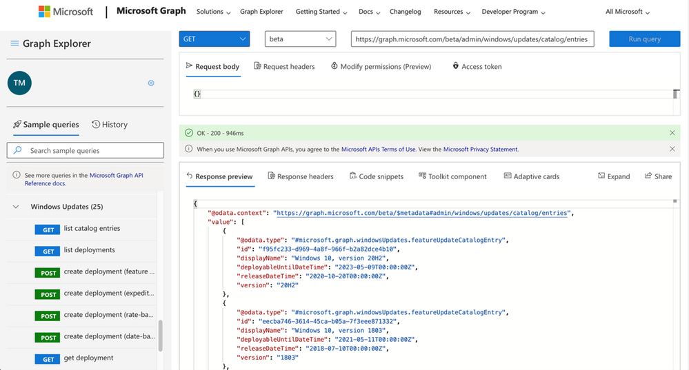
The Microsoft Graph API released today in public preview further extend these fine-grained controls, allowing customers to interact with the deployment service via apps that can help them:• Approve and schedule specific feature updates to be delivered from Windows Update on a specific date – including skipping or not taking feature updates. • Stage deployments over a period of days or weeks using rich expressions (ex: deploy 20H2 to 500 devices per day, beginning on May 11, 2021) • Bypass pre-configured Windows Update for Business policies to immediately deploy a security update across your organization. • Deliver safer update results by leveraging automatic pilots for any deployment.
Deployment service interaction via Microsoft Graph Explorer (Microsoft)
Available starting today
Customers with supported Windows or Microsoft 365 subscriptions can access the deployment services through the new APIs starting today.
To start using the new Microsoft Graph APIs today, you need one of the following subscriptions:
Windows 10 Enterprise E3 or E5 (included in Microsoft 365 F3, E3, or E5)
Windows 10 Education A3 or A5 (included in Microsoft 365 A3 or A5)
Windows Virtual Desktop Access E3 or E5
Microsoft 365 Business Premium
Devices compatible with the deployment service must be Azure AD joined or Hybrid AD joined, and run Pro, Enterprise, Education, or Pro Education editions of Windows 10, version 1709 or later.
Further information on enrolling devices for management, managing feature updates, and expediting security updates is available here.
Microsoft says that Windows devices need to be online for at least eight hours to get the latest updates and have them correctly installed after they’re released through Windows Update.
The amount of time devices running Windows are powered on and connected to Windows Update is tracked by Microsoft as ‘Update Connectivity.’
This measurement correlates the systems’ lack of enough connected time with why they’re not up to date while also making it easier to understand why some devices are unlikely to get recently released updates successfully.
According to David Guyer, a Microsoft Program Manager for Windows Updates in MEM, Windows devices need at least 8 hours online to get the latest updates and successfully install them.
“One of the most impactful things we explored was how much time a device needs to be powered on and connected to Windows Update to be able to successfully install quality and feature updates,” said Guyer.
“What we found is that devices that don’t meet a certain amount of connected time are very unlikely to successfully update. Specifically, data shows that devices need a minimum of two continuous connected hours, and six total connected hours after an update is released to reliably update.
“This allows for a successful download and background installations that are able to restart or resume once a device is active and connected.”
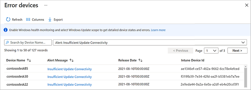
You can track devices with insufficient Update Connectivity via Microsoft Intune by navigating to Devices > Monitor and selecting either the Feature update failures or the Windows Expedited update failures report.
Insufficient Update Connectivity alerts can also be found via the Summary report in Intune by going to Reports > Windows updates > Reports > Windows Expedited update report.
Microsoft Intune Update Connectivity alerts (Microsoft)
When looking at Windows 10 devices that are not fully updated and not meeting minimum connectivity requirements, Microsoft saw that:
Approximately 50% of devices not on a serviced build of Windows 10 do not meet the minimum Update Connectivity measurement.
Approximately 25% of Windows 10 devices on a serviced build but have security updates that are more than 60 days out of date have less than the minimum Update Connectivity.
“When troubleshooting update issues, we have found it is best to select devices that have sufficient Update Connectivity,” Guyer added.
“If a device has insufficient Update Connectivity, then investigating other update issues is complicated because the low Update Connectivity can create new issues that go away once there’s enough connectivity.”
In related news, Microsoft began testing a smarter delivery method for Windows update improvements dubbed ‘Update Stack Package,’ which would deliver improvements to the update experience outside of major OS updates before monthly or feature Windows updates.
The company also redesigned cumulative updates in Windows 11 to allow security and quality updates to install faster as they are approximately 40% smaller than their Windows 10 counterparts.
Last year, Redmond released new APIs for managing Windows Update that enable devs and IT professionals to expedite Windows 10 security updates in enterprise environments.
Microsoft this week revealed that it had fended off a record number of distributed denial-of-service (DDoS) attacks aimed at its customers in 2021, three of which surpassed 2.4 terabit per second (Tbps).
One of the DDoS attacks took place in November, targeting an unnamed Azure customer in Asia and lasted a total of 15 minutes. It hit a peak throughput of 3.47 Tbps and a packet rate of 340 million packets per second (pps), making it the largest attack ever reported in history.
“This was a distributed attack originating from approximately 10,000 sources and from multiple countries across the globe, including the United States, China, South Korea, Russia, Thailand, India, Vietnam, Iran, Indonesia, and Taiwan,” Alethea Toh, product manager of Azure Networking, said.
DDoS attacks occur when several compromised devices are employed as a conduit to overwhelm a targeted server, service, or network with a flood of internet traffic with the goal of overloading the systems and disrupting its regular services.
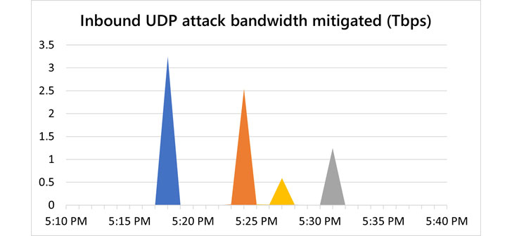
Then in December, Microsoft said it blocked two more attacks that surpassed 2.5 Tbps, both of which were aimed at customers in Asia. The first of the attacks was a 3.25 Tbps UDP attack, while the other intrusion was a 2.55 Tbps UDP flood that lingered for just a little over five minutes.
The report comes more than three months after the tech giant disclosed it acted to blunt a 2.4 Tbps DDoS attack in August 2021 targeting a European customer. Other previous record-breaking attacks include a 2.5 Tbps DDoS attack absorbed by Google in September 2017 and a volumetric strike aimed at Amazon Web Services in February 2020.
Microsoft said it observed a rise in attacks that lasted longer than an hour in the second half of 2021, whereas the proportion of short-lived attacks that were 30 minutes or less dropped from 74% to 57%. That said, the longer duration assaults are experienced as a sequence of multiple short, repeated burst attacks.
The company also said it mitigated an average of 1,955 attacks per day, with a maximum of 4,296 attacks recorded in a single day on August 10, 2021. For the entirety of H2 2021, no fewer than 359,713 unique attacks against its infrastructure were blocked, a 43% increase from the first half of 2021.
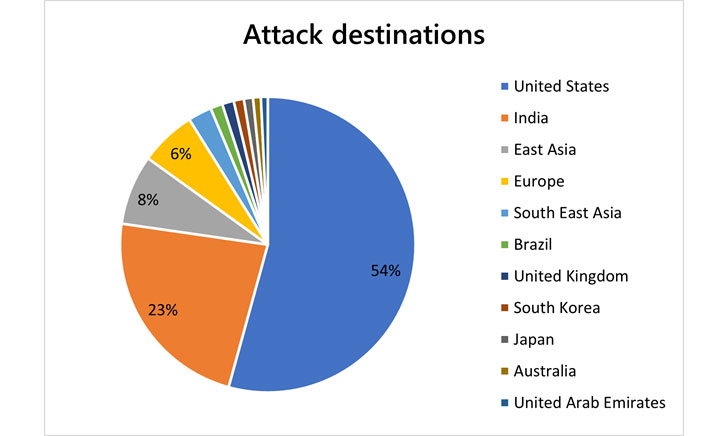
The gaming industry emerged as the hardest hit sector, followed by financial institutions, media, internet service providers (ISPs), retail, and supply chain entities. Most of the targeted organizations were located in the U.S., India, East Asia (Hong Kong), Brazil, the U.K., South Korea, Japan, Australia, and the U.A.E.
“We saw a sharp uptick in attacks in India, from just 2% of all attacks in the first half of 2021 to taking the second position at 23% of all attacks in the second half of 2021,” Toh said. “Another driving factor may be that the acceleration of digital transformation, for example, the ‘Digital India‘ initiative, has increased the region’s overall exposure to cyber risks.”
If you start a program and receive an error stating that the program you are trying to run needs the Microsoft Visual C++ 2015 Runtime, you can use this tutorial to install the package so that your program works again.
When developers create a Windows program using Microsoft Visual Studio 2015, there are specific dynamic link libraries (DLLs) that their programs are linked to work correctly.
These DLLs are distributed through the Microsoft Visual C++ 2015 Runtime, and if the package is not installed, users will encounter errors stating that DLLs are missing or you need to install the runtime.
As an example, the video game Valorant released an update today that did not include the Microsoft Visual C++ 2015 Runtime, causing the game not to work after the update was installed.
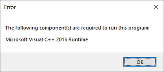
When users launch Valorant, they are instead greeted with the following error.
Missing Microsoft Visual C++ 2015 Runtime error
“The following component(s) are required to run this program: Microsoft Visual C++ 2015 Runtime”
The good news is that it is really easy to fix this problem by downloading and install the runtime from Microsoft’s website.
To install the Microsoft Visual C++ 2015 Runtime, please follow these steps:
You will be brought to a page where it asks you to select whether you want to download the 32-bit or 64-bit version of Windows. Select the version you need and click the Next button. If you are unsure what version you need, you can use this tutorial to determine what you need.
BleepingComputer suggests that you download and install both the x86 AND x64 versions of the runtime to not run into issues in the future.
The files will now be download to your computer. Once downloaded, double-click on the downloaded vc_redist.x64.exe file.
The Microsoft Visual C++-2015 Redistributable screen will be displayed and ask you to agree to the license terms and conditions. Put a checkmark in the “I agree” box and then click on the Install button.Microsoft Visual C++-2015 Redistributable
If Windows prompts you to allow the program to make changes or continue, click on the Yes or Allow button.
When done, the program will display a message stating that it was successfully installed.Redistributable Installed
Now perform the same steps to install the vc_redist.x86.exe runtime.
You can now close the installer.
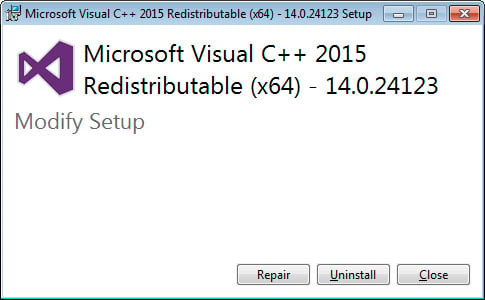
If you already had the Visual C++ 2015 Runtime installed, you can run the above redistributables and perform a repair.
Perform a Repair
You can now try to run the program that previously gave the missing runtime error, and it should work again.
 The config can also be exported if preferred. The following example exports the output to the
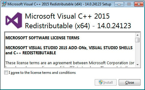 Microsoft Visual C++-2015 Redistributable
 Redistributable Installed