Best Practices for setting up Altaro VM Backup

This best practice guide goes through the Altaro VM Backup features explaining their use and the optimal way to configure them in order to make the best use out of the software.

You will need to adapt this to your specific environment, especially depending on how much resources you have available, however this guide takes you through the most important configurations that are often overlooked too.

Setting up the Altaro VM Backup Management Console

The Altaro VM Backup Management Console can be utilised to add and manage multiple hosts in one console. However these hosts must be in the same LAN and at the same physical site (same building). Setups with multiple physical sites must have an instance of Altaro VM Backup at each site.

To manage these multiple installations, you can utilise the ‘Central Monitoring Console’ where you’ll be able to monitor as well as manage these Altaro VM Backup installations remotely.

A single Altaro VM Backup instance can manage both Hyper-V & VMware hosts.

For optimal results, Altaro runs some maintenance specific tasks using (multiple) single threaded operations. For this reason installing on a machine which has a CPU with a higher single thread performance would yield better results than installing on a machine which has a CPU with more cores and lower single thread performance.

Thus for the fastest results, installing Altaro VM Backup on a machine with a higher single thread CPU speed would be best.

Backup Locations

Make sure Opportunity Locks (Oplocks) are disabled if the backup location is a NAS.

If your backup location is a Windows machine, the equivalent to Oplocks is: Set-SmbServerConfiguration -EnableLeasing 0

Run the above command via Powershell.

Offsite Copies

With Altaro VM Backup, you are provided with the functionality of an Offsite Copy Location, which is a redundant/secondary copy of your backups. You can even backup your VM’s to 2 different offsite copy locations for further redundancy of your data, so you can pick a cloud location as well as an Altaro Offsite Server for instance.

There are multiple options for setting this up:

  • You can choose a Physical Drive connected to the management console (the best practice for offsites is to have them located in another building/location).
  • Drive Rotation/Swap which allows you to set up a pool of drives/network paths.
  • A Network Path (LAN Only) or else to an offsite location via a WAN/VPN/Internet connection, which is an ideal tool for Disaster Recovery purposes. Please note that the latter situation (non-LAN) requires use of the Altaro Offsite Server
  • Backup to Microsoft AzureAmazon S3 or Wasabi.

Setting up an offsite copy location is as crucial as setting up backups to a primary location. Apart from the obvious reason that you’ll have a redundant set of backups to restore from, should the local backups become unusable due to disk corruption or other disk failures. Having a secondary copy of your backup sets also allows you to keep a broader history for your VM backups on your secondary location and you’ll be able to go further back when restoring if required.

Deduplication

Altaro VM Backup makes use of Augmented In-line Deduplication. Enabling this is highly recommended and is done from the ‘Advanced Settings’ screen as this will essentially ensure that any common data blocks across virtual machines are only written to the backup location once. This helps by saving a considerable amount of space and also makes backups much quicker since common information is only transferred once.

Boot From Backup

The Boot From Backup drive feature comes along with 2 options, either ‘Verification Mode’ or ‘Recovery Mode’. This is a very good option for getting your RTO down since you’re able to boot up the VM immediately from a backup location and start a restore in the background as well.

However it’s very important that if you are planning to do this, you’ll need a fast backup location that can handle the I/O of a booted VM that’s essentially going into production. Please note that when the VM has finished restoring, it’s suggested to restart the restored VM as soon as you get a chance in order to switch to the restored drives, which would have faster I/O throughput.

Notifications

E-mail notifications are a simple and effective method of monitoring the backup status, yet it’s often overlooked. Setting up these notifications will provide you with a quick overview of the status over your of your backup jobs, hence – you won’t need to login into the Altaro Management console every day to confirm the backup status.

This way you’ll be alerted of any backup failures, allowing you to address said issues before the next backup schedule. Thereby ensuring that you always have a restorable backup point; so as a general best practice, always monitor your backup notifications.

Master Encryption Key

The Master Encryption Key in Altaro is utilised to encrypt the backups using AES 256-bit. It’s used if you choose to encrypt the local backups from the ‘Advanced Settings’ screen, while if you’re configuring offsite copies it must be used as offsite copies must be encrypted.

Altaro VM Backup will require the encryption key upon restoring, so it’s critical that you either remember it or take note of it in a secure password manager as there is no method of recovery for the master encryption key.

Scheduled Test Drills

Altaro VM Backup has the ability to run manual or automated verification of your backup data. This allows you to run scheduled verification jobs that will check the integrity of your backups on your backup location, or schedule full VM restores so that you can actually boot up the VM and confirm that everything works as expected. The VM will be restored with the NIC disabled so as to avoid IP conflicts with the production machine as well.

Failure of storage devices is not uncommon, therefore scheduling test drills is strongly advised for added peace-of-mind. Full instructions on configuring test drills.

Other General Best Practices

  • Backups and production VM’s should not be placed on the same drive.
  • Make sure Opportunity Locks (Oplocks) are disabled if the backup location is a NAS.
  • Backups should not be placed on a drive where an OS is running.
  • Altaro uses the drive it’s installed on as temporary storage and will require a small amount of free space (varying according to the size of the VMs being backed up).
  • Keep at least 10% of the backup location free.
  • The main Altaro VM Backup installation should not be installed on a machine that is also a domain controller (DC).
  • Directories/files inside the Altaro backup folder should not be tampered with, deleted or moved.
  • Do not take snapshots DFSR databases: “Snapshots aren’t supported by the DFSR database or any other Windows multi-master databases. This lack of snapshot support includes all virtualization vendors and products. DFSR doesn’t implement USN rollback quarantine protection like Active Directory Domain Services.” Source. 

Best Practices for Replication

Exclude Page File from Backup

As you’re aware Altaro VM Backup will take note of all changes since the last backup and transfer over all of the blocks that changed to the backup location. The page file will be changing very often and potentially causing your replication jobs to take longer.

Therefore, excluding the page file from backup equals, less transferred changes and as a result the replication jobs takes less time. This can be done by placing the page file onto a separate VHDX/VMDK file from the VM itself and then you can follow the steps here, in order to exclude the VHDX/VMDK file.

High Disk IO and Hypervisor Performance

Replication needs to make use of CDP (Continuous Data Protection), in order to take a backup every couple of minutes/hours, which makes Replication possible.

It’s important to note however that you should only enable high-frequency CDP (15 minutes or less) on VM’s that you really need to. This will ensure that the VM’s you really need to will be able to achieve the selected maximum frequency and in order not to have an impact your Hypervisor’s performance.

Source :
https://help.altaro.com/support/solutions/articles/43000467315-best-practices-for-setting-up-altaro-vm-backup

Altaro Dealing with “volsnap” errors in the System event log

The volsnap source errors are events that are listed in the Windows System event log. Such events usually contain relevant troubleshooting information as to why the shadow copy got dismounted and as a result causes the backups to fail.

You can refer to this article showcasing the error seen in Altaro.

Below you can find a couple of ‘volsnap’ events that we’ve encountered along with their solutions:


Error Message:

volsnap Event ID 25

The shadow copies of volume D: were deleted because the shadow copy storage could not grow in time. Consider reducing the IO load on the system or choose a shadow copy storage volume that is not being shadow copied.

Solution:

This error is logged due to the source drive experiencing a high IO load and thereby it causes the shadow copy to dismount, as a result causing a backup failure.  In this case you can choose to re-schedule the backup job when there is less IO on the source disk. In addition to that something that will help alleviate the IO on the source disk is placing the shadow copies onto another drive completely.

You’ll need to ensure that you have a disk with enough (10% of the original source) and it should also be a disk with on-per performance as the source.

You can run the following command on the host in order to place the shadow copy on another disk; drive letters need to be changed accordingly:

vssadmin add shadowstorage /For=D: /On=E: /MaxSize=UNBOUNDED
vssadmin resize shadowstorage /For=D: /On=E: /MaxSize=UNBOUNDED

Text

Adjusting the page file to 1.5 times the amount of RAM can also help the situation. Note that if you set the it to the maximum page file available, you will be required to restart the machine. Increases (not going up to the maximum) do not typically require a restart.


Error Message:

volsnap Event ID 16

The shadow copies of volume D: were aborted because volume D:, which contains shadow copy storage for this shadow copy, was force dismounted.

volsnap Event ID 14

The shadow copies of volume D: were aborted because of an IO failure on volume D:

Solution:

These two events are usually coupled together. This usually points to a disk issue on the drive being referenced and there should be ‘Disk’ or ‘Ntfs’ events at the same time that give more information on the issue.


Error Message:

volsnap Event ID 24

There was insufficient disk space on volume D: to grow the shadow copy storage for shadow copies of D:. As a result of this failure all shadow copies of volume D: are at risk of being deleted.

volsnap Event ID 35

The shadow copies of volume D: were aborted because the shadow copy storage failed to grow.

Solution:

These two events are usually coupled together. In this case it means that the shadow copy was dismounted due to insufficient disk space on the volume. Please ensure that you have at least 10% free space on the source drives and then run the backup again.


Error Message:

volsnap Event ID 36

The shadow copies of volume D: were aborted because the shadow copy storage could not grow due to a user imposed limit.

Solution:

This particular volsnap error means that the current limit imposed is limiting the shadow copy from growing any larger and hence it’s causing the shadow copy to dismount and cause the backup to fail. To resolve this error you can run the following commands to expand the ShadowStorage; drive letters need to be changed accordingly:

vssadmin add shadowstorage /For=D: /On=D: /MaxSize=UNBOUNDED
vssadmin resize shadowstorage /For=D: /On=D: /MaxSize=UNBOUNDED

Text


Also note that in case you’re using a CSV (Clustered Shared Volume), instead of a drive letter being listed in the event log, there will be an empty space.

Source :
https://help.altaro.com/support/solutions/articles/43000494972

What are the system requirements for Altaro VM Backup?

update november 2023

Version 9

The VM Backup Management Console can be utilized to add and manage multiple hosts in one console. However these hosts must be in the same LAN and at the same physical site (same building). Setups with multiple physical sites must have an instance of VM Backup at each site.


Supported Hypervisors (Hosts)

Microsoft Hyper-V

  • Windows Server 2008 R2 SP1 (Only with .NET Framework 4.8 or higher)
  • Windows Hyper-V Server 2008 R2 SP1 (core installation) (Only with .NET Framework 4.8 or higher)
  • Windows Server 2012
  • Windows Hyper-V Server 2012 (core installation)
  • Windows Server 2012 R2
  • Windows Hyper-V Server 2012 R2 (core installation)
  • Windows Server 2016
  • Windows Server 2016 (desktop experience)
  • Windows Hyper-V Server 2016 (core installation)
  • Windows Server 2019
  • Windows Hyper-V Server 2019 (core installation)
  • Windows Server 2022
  • Windows Hyper-V Server 2022 (core installation)
  • Azure Stack HCI

VMware

  • vSphere: 5.5 / 6.0 / 6.5 / 6.7 / 7.0 / 8.0
  • vCenter: 5.5 / 6.0 / 6.5 / 6.7 / 7.0 / 8.0
  • ESXi: 5.5 / 6.0 / 6.5 / 6.7 / 7.0 / 8.0

Note: vSphere/vCenter/ESXi 5.0/5.1 are no longer supported in V9

It’s important to note the version combination between ESXi and vCenter.

Note that the Free version of VMware ESXi is not supported as it lacks components required by VM Backup.

When making use of the NBD Transport mode, virtual disks cannot be larger than 1TB each. More information here.

Pass-through or RDM (Raw Device Mappings) are not backed up.

Supported Operating Systems

The VM Backup products can be installed on the following OS’s:

VM Backup

  • Windows Server 2008 R2 SP1 (Only with .NET Framework 4.8 or higher)
  • Windows Hyper-V Server 2008 R2 SP1 (core installation) (Only with .NET Framework 4.8 or higher)
  • Windows Server 2012
  • Windows Hyper-V Server 2012 (core installation)
  • Windows Server 2012 R2
  • Windows Hyper-V Server 2012 R2 (core installation)
  • Windows Server 2016
  • Windows Server 2016 (desktop experience)
  • Windows Hyper-V Server 2016
  • Windows Server 2019
  • Windows Hyper-V Server 2019
  • Windows Hyper-V Server 2019 (core installation)
  • Windows Server 2022
  • Azure Stack HCI

    Note that hosts must be in the same LAN and at the same physical site (same building). Setups with multiple physical sites must have an instance of VM Backup at each site.

Management Tools (UI)

  • Windows 2008 R2 SP1 (Only with .NET Framework 4.8 or higher)
  • Windows Server 2012
  • Windows Server 2012 R2
  • Windows Server 2016 (desktop experience)
  • Windows Server 2019
  • Windows Server 2022
  • Azure Stack HCI
  • Windows 7 (64-Bit)
  • Windows 8 (64-Bit)
  • Windows 10 (64-Bit)
  • Windows 11 (64-Bit)

Offsite Backup Server

  • Windows 2008 R2 SP1 (Only with .NET Framework 4.8 or higher)
  • Windows Hyper-V Server 2008 R2 SP1 (core installation) (Only with .NET Framework 4.8 or higher)
  • Windows Server 2012 
  • Windows Hyper-V Server 2012 (core installation)
  • Windows Server 2012 R2
  • Windows Hyper-V Server 2012 R2 (core installation)
  • Windows Server 2016
  • Windows Server 2016 (desktop experience)
  • Windows Hyper-V Server 2016
  • Windows Server 2019
  • Windows Hyper-V Server 2019
  • Windows Server 2022
  • Azure Stack HCI


Replication Support

[Hyper-V] A Windows Server OS is required for replication. The Offsite Backup Server needs to be installed on a Windows Server OS that’s matching the source host OS, where the production VMs are running. Below you can find a list supported OS’s that you can replicate to:

Host OSSupported Replication Offsite Backup Server OS
2012to 2012
2012R2to 2012R2
2016to 2016
2019to 2019
2022to 2022
Azure Stack HCIAzure Stack HCI

[VMware] The host added to the Offsite Backup Server must be the same OS as the source host being replicated from. Below you can find a list supported OS’s that you can replicate to:

Host OSSupported Replication Host OS
5.5to 5.5
6.0to 6.0
6.5to 6.5
6.7to 6.7
7.0to 7.0
8.0to 8.0

Required Hardware Specifications

VM Backup

  • Minimum of i5 (or equivalent – minimum 4 cores recommended) processor
  • 2 GB RAM + an additional 25MB RAM for every 100GB of data being backed up
  • 1 GB Hard Disk Space (for VM Backup Program and Settings) + 15 GB (for temporary files created during backup operations)
  • Minimum of 10% free disk space on each volume holding live VM data to be used for Microsoft Volume Shadow Copy
  • Minimum of 10% free disk space on each backup location holding backup data to ensure smooth operation

Hyper-V Host Agent

  • 1 GB RAM
  • 2 GB Hard Disk Space

Offsite Backup Server

  • Minimum of i5 (or equivalent – minimum 4 cores recommended) processor
  • 2 GB RAM + an additional 25MB RAM for every 100GB of data being backed up
  • For Replication, ensure that it has enough resources to boot your VMs

Software Prerequisites

  • MS .NET Framework 4.8
  • Minimum screen resolution for the Management console: 1280×800
  • One of the listed supported Operating Systems must be used (Windows client operating systems are not supported unless specified)
  • The main VM Backup installation cannot be installed on a machine that is also a domain controller (DC)

Communication Ports

Below is a list of the default TCP ports used by our software and their purpose. All these ports must be allowed.

36014 : Communication between Management Console UI and VM Backup

36015 : Communication from VM Backup to API Service

36021 & 36022 : Communication between the Host Agents and VM Backup

36023 : Communication from VM Backup to Host Agents

36070 : Communication for the Deduplication Service

36000 & 36001 : Communication from v9 Clients with the Offsite Backup Server

36050 : Communication from Offsite Backup Server UI to Offsite Backup Server

36100 : Communication from VM Backup to the Offsite Backup Server for Replication

36075: Communication for the Deduplication Service for the Offsite Backup Server

36200 – 36220 : Communication from VM Backup to Agents for Boot From Backup

80 & 443 : For Offsite copies to Azure Storage Accounts, Amazon S3 & Wasabi

443 & 7444 & 902 : Communication to VMware Hosts

Supported Backup Locations

  • USB External Drives
  • eSata External Drives
  • USB Flash Drives
  • Fileserver Network Shares using UNC Paths
  • NAS devices (Network Attached Storage) using UNC Paths
  • PC Internal Hard Drives (recommended only for evaluation purposes)
  • RDX Cartridges
  • Offsite Backup Server (incl. Replication)
  • Azure Cloud Storage Account
  • Amazon S3
  • Wasabi Cloud Storage Account

Note: The backup locations must be in the same LAN and at the same physical site (same building) as the VM management machine and the hosts, with the exception of the Offsite Backup Server/Cloud locations.

Note: Target storage partitions must be either of the below:

  • NTFS/ReFS formatted
  • Network Paths and accessible by SMB3.0

Note: Please ensure that the backup location chosen does not perform any sort of deduplication outside that of VM Backup.

Note: SMB file shares in Cloud locations (such as Azure Files) are not supported as a backup location.

Boot from Backup Requirements

  • For Hyper-V Windows Server 2012 Host OS and onward are supported for Boot from Backup Drive. The Microsoft iSCSI Initiator Service has to be running on the machine you’re attempting to boot to.
  • VMware requires ports 36200 – 36220 open on the firewall and it also requires an iSCSI Storage AdapterMore information on that here.
  • The datastore chosen for must be VMFS.
  • VMs with Storage Spaces volumes are not supported.

File Level/Exchange Item Level Restore Requirements

  • The partition must be NTFS ReFS (through Instant Mount – only for File Level Restores) formatted
  • The partition must be formatted as ‘Basic’ and not ‘Dynamic’
  • If the VM has Windows Data Deduplication role enabled, the role must also be enabled where the VM Backup machine is installed (through Instant Mount)
  • The files must NOT be encrypted or compressed at guest OS (VM) level
  • Exchange Item Level Restores are only supported from NTFS formatted partitions
  • Storage Spaces volumes are not supported for file level recovery
  • The following Microsoft Exchange versions are supported:
    • 2007 (up to SP3)
    • 2010 (up to SP3)
    • 2013 (from RTM up to CU21, with the exception of CU 2, 3 and 4)
    • 2016 (up to CU22)
    • 2019 (up to CU11)

Hyper-V Restore Version Compatibility

Virtual Machines backed up from Windows Server 2008 R2 SP1 and 2012 hosts have to be restored to hosts running Windows Server 2016 build 1607 or older.

Virtual machines backed up from Windows Server 2012 R2 and newer can be restore to hosts running up to Windows Server 2019. While VMs backed up from WS2016 and newer can be restored to hosts running WS 2022.

Naturally, you can restore to a newer operating system, but not to an older one i.e. you will be able to restore a VM backed up from a 2008 R2 SP1 host to a 2012 one, but not the other way round.

Please note that this also applies when restoring a single virtual hard disk as well.

Version 8

The VM Backup Management Console can be utilized to add and manage multiple hosts in one console. However these hosts must be in the same LAN and at the same physical site (same building). Setups with multiple physical sites must have an instance of VM Backup at each site.


Supported Hypervisors (Hosts)

Microsoft Hyper-V

  • Windows Server 2008 R2 SP1
  • Windows Hyper-V Server 2008 R2 SP1 (core installation)
  • Windows Server 2012
  • Windows Hyper-V Server 2012 (core installation)
  • Windows Server 2012 R2
  • Windows Hyper-V Server 2012 R2 (core installation)
  • Windows Server 2016
  • Windows Server 2016 (desktop experience)
  • Windows Hyper-V Server 2016 (core installation)
  • Windows Server 2019
  • Windows Hyper-V Server 2019 (core installation)
  • Windows Server 2022
  • Windows Hyper-V Server 2022 (core installation)
  • Azure Stack HCI

VMware

  • vSphere: 5.0 / 5.1 / 5.5 / 6.0 / 6.5 / 6.7 / 7.0
  • vCenter: 5.0 / 5.1 / 5.5 / 6.0 / 6.5 / 6.7 / 7.0
  • ESXi: 5.0 / 5.1 / 5.5 / 6.0 / 6.5 / 6.7 / 7.0

It’s important to note the version combination between ESXi and vCenter.

Note that the Free version of VMware ESXi is not supported as it lacks components required by VM Backup.

When making use of the NBD Transport mode, virtual disks cannot be larger than 1TB each. More information here.

Pass-through or RDM (Raw Device Mappings) are not backed up.

Backing up VMs that have fault tolerance enabled is not supported because when FT is enabled, it is not possible to take snapshots of those virtual machines, which is one of the criteria for AVMB to be able to take a backup of a VM.

Restoring to a vVol (VMware Virtual Volume) Datastore is not supported.

Supported Operating Systems

The VM Backup products can be installed on the following OS’s:

VM Backup

  • Windows Server 2008 R2 SP1
  • Windows Hyper-V Server 2008 R2 SP1 (core installation)
  • Windows Server 2012
  • Windows Hyper-V Server 2012 (core installation)
  • Windows Server 2012 R2
  • Windows Hyper-V Server 2012 R2 (core installation)
  • Windows Server 2016
  • Windows Server 2016 (desktop experience)
  • Windows Hyper-V Server 2016
  • Windows Server 2019
  • Windows Hyper-V Server 2019
  • Windows Hyper-V Server 2019 (core installation)
  • Windows Server 2022
  • Windows Hyper-V Server 2022
  • Windows Hyper-V Server 2022 (core installation)
  • Azure Stack HCI

    Note that hosts must be in the same LAN and at the same physical site (same building). Setups with multiple physical sites must have an instance of VM Backup at each site.

Management Tools (UI)

  • Windows 2008 R2 SP1
  • Windows Server 2012
  • Windows Server 2012 R2
  • Windows Server 2016 (desktop experience)
  • Windows Server 2019
  • Windows Server 2022
  • Azure Stack HCI
  • Windows 7 (64-Bit)
  • Windows 8 (64-Bit)
  • Windows 10 (64-Bit)

Offsite Backup Server

  • Windows 2008 R2 SP1
  • Windows Hyper-V Server 2008 R2 SP1 (core installation)
  • Windows Server 2012 
  • Windows Hyper-V Server 2012 (core installation)
  • Windows Server 2012 R2
  • Windows Hyper-V Server 2012 R2 (core installation)
  • Windows Server 2016
  • Windows Server 2016 (desktop experience)
  • Windows Hyper-V Server 2016
  • Windows Server 2019
  • Windows Hyper-V Server 2019
  • Windows Server 2022
  • Windows Hyper-V Server 2022
  • Azure Stack HCI


Replication Support

[Hyper-V] A Windows Server OS is required for replication. The Offsite Backup Server needs to be installed on a Windows Server OS that’s matching the source host OS, where the production VMs are running. Below you can find a list of supported OS’s that you can replicate to:

Host OSSupported Replication Offsite Backup Server OS
2012to 2012
2012R2to 2012R2
2016to 2016
2019to 2019
2022to 2022
Azure Stack HCIAzure Stack HCI

[VMware] The host added to the Offsite Backup Server must be the same OS as the source host being replicated from. Below you can find a list of supported OS’s that you can replicate to:

Host OSSupported Replication Host OS
5.5to 5.5
6.0to 6.0
6.5to 6.5
6.7to 6.7
7.0to 7.0

Required Hardware Specifications

VM Backup

  • Minimum of i5 (or equivalent – minimum 4 cores recommended) processor
  • 1 GB RAM + an additional 25MB RAM for every 100GB of data being backed up
  • 1 GB Hard Disk Space (for VM Backup Program and Settings) + 15 GB (for temporary files created during backup operations)
  • Minimum of 10% free disk space on each volume holding live VM data to be used for Microsoft Volume Shadow Copy

Hyper-V Host Agent

  • 500 MB RAM 

Offsite Backup Server

  • Minimum of i5 (or equivalent – minimum 4 cores recommended) processor
  • 1 GB RAM + an additional 25MB RAM for every 100GB of data being backed up
  • For Replication, ensure that it has enough resources to boot your VMs

Software Prerequisites

  • MS .NET Framework 4.7.2 
  • Minimum screen resolution for the Management console: 1280×800
  • One of the listed supported Operating Systems must be used (Windows client operating systems are not supported unless specified)

Communication Ports

Below is a list of the default TCP ports used by our software and their purpose. All these ports must be allowed.

35106 : Communication for VMware 6.5, Backup and Restore operations.

35107 : Communication between Management Console UI and VM Backup

35108 : Communication from VM Backup to Hyper-V Host Agents

35113 : Communication from VM Backup to API Service

35114 : Communication for the Deduplication Service 

35116 & 35117 : Communication from v8 Clients with the Offsite Backup Server

35119 : Communication from Offsite Backup Server V8 UI to Offsite Backup Server

35120 : Communication from VM Backup to the Offsite Backup Server for Replication

35121 : Communication for the Deduplication Service for Amazon S3/Wasabi offsite locations

35221 : Communication between the Hyper-V Host Agents and VM Backup

35200 – 35220 : Communication from VM Backup to Agents for VMware Boot From Backup

80 & 443 : For Offsite copies to Azure Storage Accounts, Amazon S3 & Wasabi

443 & 7444 & 902 : Communication to VMware Hosts

Supported Backup Locations

  • USB External Drives
  • eSata External Drives
  • USB Flash Drives
  • Fileserver Network Shares using UNC Paths
  • NAS devices (Network Attached Storage) using UNC Paths
  • PC Internal Hard Drives (recommended only for evaluation purposes)
  • RDX Cartridges
  • Offsite Backup Server (incl. Replication)
  • Azure Cloud Storage Account
  • Amazon S3
  • Wasabi Cloud Storage Account

Note: The backup locations must be in the same LAN and at the same physical site (same building) as the VM management machine and the hosts, with the exception of the Offsite Backup Server/Cloud locations.

Note: Target storage partitions must be either of the below:

  • NTFS/ReFS formatted
  • Network Paths and accessible by SMB3.0

Note: Please ensure that the backup location chosen does not perform any sort of deduplication outside that of VM Backup.

Note: SMB file shares in Cloud locations (such as Azure Files) are not supported as a backup location.

Boot from Backup Requirements

  • For Hyper-V Windows Server 2012 Host OS and onward are supported for Boot from Backup Drive. The Microsoft iSCSI Initiator Service has to be running on the machine you’re attempting to boot to.
  • VMware requires ports 35200 – 35220 open on the firewall and it also requires an iSCSI Storage AdapterMore information on that here.
  • The datastore chosen must be VMFS.
  • VMs with Storage Spaces volumes are not supported.

File Level/Exchange Item Level Restore Requirements

Hyper-V Restore Version Compatibility

Virtual Machines backed up from Windows Server 2008 R2 SP1 and 2012 hosts have to be restored to hosts running Windows Server 2016 build 1607 or older.

Virtual machines backed up from Windows Server 2012 R2 and newer can be restored to hosts running up to Windows Server 2019. While VMs backed up from WS2016 and newer can be restored to hosts running WS 2022.

Naturally, you can restore to a newer operating system, but not to an older one i.e. you will be able to restore a VM backed up from a 2008 R2 SP1 host to a 2012 one, but not the other way round.

Please note that this also applies when restoring a single virtual hard disk as well.

Have more questions? Submit a request

Source :
https://support.hornetsecurity.com/hc/en-us/articles/19687996547601

Ubiquiti UniFi – USG/UDM: Configuring Internet Security Settings

Overview

After reading this article users should gain the knowledge to be able to configure and maintain the IPS/IDS functionality on their UniFi networks. NOTES & REQUIREMENTS:Applicable to the following:

  • UniFi Network version 5.9+
  • UniFi Security Gateway platform firmware 4.4.18+
  • UniFi Dream Machine platform

Table of Contents

  1. Introduction
  2. Network Diagram
  3. Intrusion Detection and Prevention
    1. Categories
    2. Whitelisting
    3. Signature Suppression 
  4. GeoIP Filtering
  5. DNS Filters 
    1. Filter Levels
  6. Deep Packet Inspection
    1. DPI Restrictions (Layer 7 Filters)
  7. Network Scanners
    1. Internal Honeypot
      1. Honeypot Services
  8. Testing & Verification
  9. Privacy Statement
  10. Related Articles

Introduction

An intrusion prevention system (IPS) is an engine that identifies potentially malicious traffic based on signatures. The signatures contain known traffic patterns or instruction sequences used by malware. This type of signature-based engine can only detect anomalies based on known malicious traffic patterns.

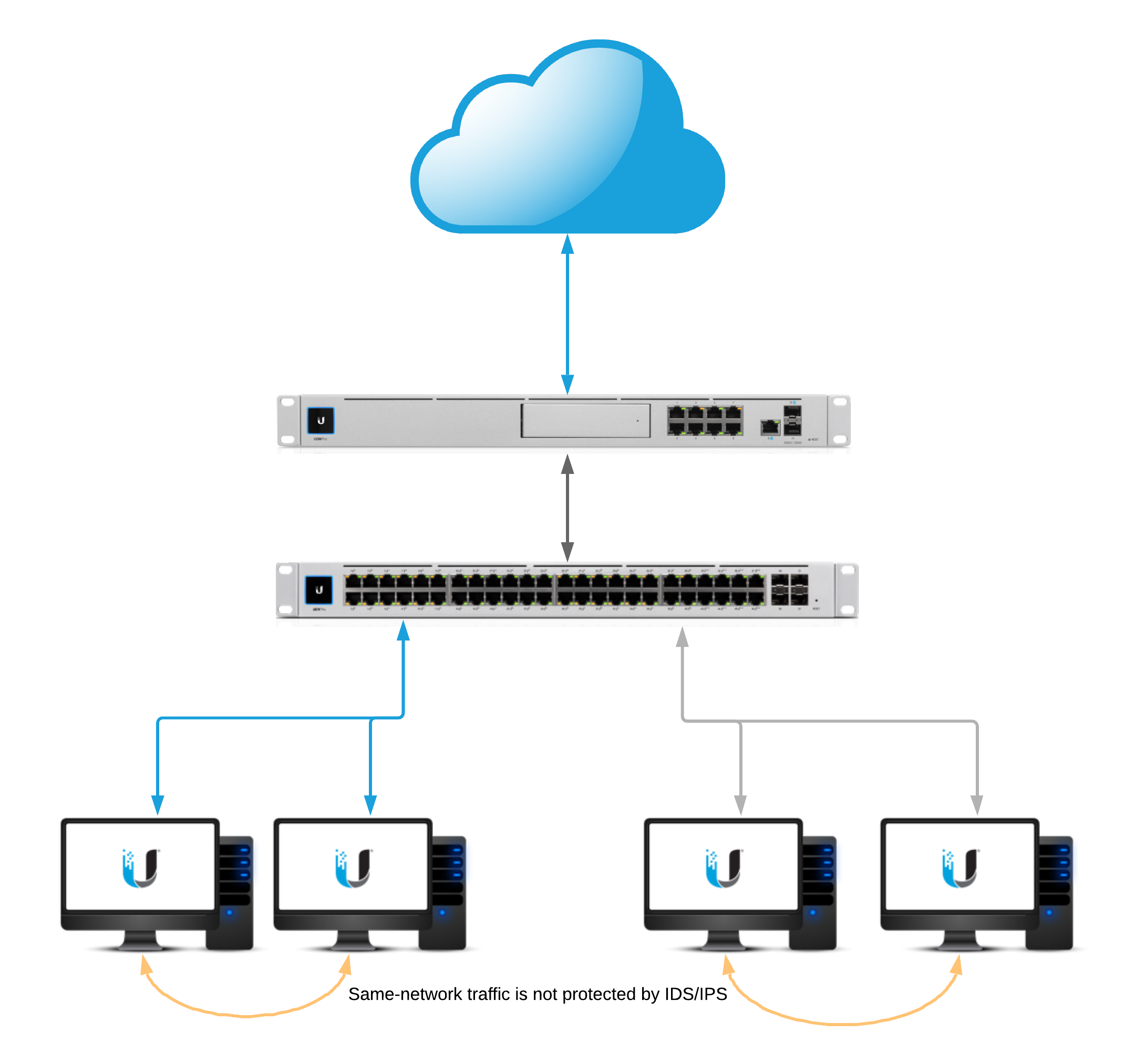
Network Diagram

idsIps.png

Intrusion Detection and Prevention

To enable intrusion detection or intrusion prevention, navigate to the Settings > Security section of the UniFi Network application. ATTENTION:

  • Enabling IDS or IPS will affect the maximum throughput on inter-VLAN and egress traffic.
    • USG: 85 Mbps*
    • USG-Pro: 250 Mbps*
    • USG-XG: 1 Gbps*
  • Enabling Smart Queues or DPI on top of IPS/IDS will also incur a further throughput penalty to maximum throughput.
  • UniFi Dream Machine throughput: 850 Mbps*
  • UniFi Dream Machine Pro: 3.5Gbps*

*Values are rough estimates and can vary depending on configuration.

Threat Management Modes

  • Intrusion Detection System: When set will automatically detect, and alert, but will not block potentially malicious traffic. 
  • Intrusion Prevention System: When set will automatically detect, alert, and block potentially malicious traffic. 

Firewall Restrictions

These restrictions can be found under New Settings > Internet Security > Advanced.

  • Restrict Access to ToR: When enabled will block access to The Onion Router. 
  • Restrict Access to Malicious IP Addresses: When enabled will block access to IP addresses or blocks of addresses that have been recognized as passing malicious traffic. 

System Sensitivity Levels

mceclip3.png

The “system sensitivity levels” are pre-defined levels of security categories that will be loaded into the threat management daemon. Each level increase requires more memory and CPU usage. Additionally the “custom” level is utilized when manually selection categories.

Categories

ATTENTION:

  • Due to the amount of available memory on the USG3 and UDM a limited selection of categories can be enabled.
  • Click below to see a full list of categories.

Categories and Their Definitions

Click Here to Expand the IPS/IDS Categories Section

NOTE:The following configuration can be found in the Advanced tab of Internet Security.

Whitelisting

The Threat Management Allow List function of the IPS engine allows a UniFi Administrator to create a list of trusted IP’s. The traffic, depending on the direction selected, will not get blocked to or from the identified IPs. 

Create a new allow list within Settings > Security > Internet Threat Management > Advanced.

Signature Suppression

The signature suppression function of the IPS engine allows a UniFi Administrator to mute the alerting on certain signatures. This will also disable blocking on traffic matching the designated suppression rule. 

mceclip2.png
  • Adding a signature suppression rule for all traffic will suppress the signature regardless of host IP. 
  • Adding a signature suppression rule with packet tracking based on traffic direction and by single IP, defined UniFi Network, or subnet of choice. 

GeoIP Filtering

NOTE:For GeoIP Filtering to work on the USG, hardware offloading must be enabled. When Threat Management is enabled (under Settings > Internet Security > Threat Management), hardware offloading is disabled. Only one of these two features can be enabled at a time on the USG.

Blocking

Blocking individual countries can be configured on the Threat Management Dashboard section. Blocking is as easy as navigating to the map, clicking on a country, and confirming by clicking “Block”.

mceclip0.png

Unblocking

Unblocking a country can be by performed on the Threat Management Dashboard by navigating to the left side of the map on the Overview tab. A list of blocked countries will be populated. Simply hover over the county that is to be unblocked and an “unblock” option will appear. Select “unblock” and the country will be taken off of the list. 

mceclip1.png

Traffic Direction

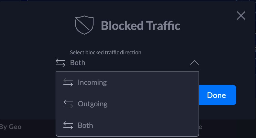
UniFi Network allows configuring the GeoIP filtering traffic direction. Follow the steps below:

    1. Navigate to the top of the Threat Management Dashboard and select the direction. Screen_Shot_2019-11-21_at_3.58.16_PM.png

    2. Select the traffic direction.

Screen_Shot_2019-11-21_at_4.00.26_PM.png

    3. Click Done.

DNS Filters

ATTENTION:

  • DNS Filtering is only available on the UniFi Dream Machine. 
  • Clients that use VPN, DNS-over-HTTPS, or DNS-over-TLS will have non-standard DNS requests that will not be seen by the UniFi Dream Machine. 

The DNS Filter feature allows administrators to select levels of filtering per-network. This ensures that any DNS requests that go out from clients on configured LANs adhere to the filtering levels. 

    1. To configure DNS Filters, navigate to New Settings > Internet Security > DNS Filters.

mceclip0.png

    2. Enable DNS Filtering by clicking the slider button.

    3. Select Add Filter.

    4. Choose the desired level of filtering for the LAN. 

    5. Select which network this filter should apply to and confirm the selection. 

    6. DNS filtering will be enabled at this point. 

Filter Levels

Security

Blocks access to phishing, spam, malware, and malicious domains. The database of malicious domains is updated hourly. Note that it does not block adult content.

Adult

Blocks access to all adult, pornographic and explicit sites. It does not block proxy or VPNs, nor mixed-content sites. Sites like Reddit are allowed. Google and Bing are set to the “Safe Mode”. Malicious and Phishing domains are blocked.

Family

Blocks access to all adult, pornographic and explicit sites. It also blocks proxy and VPN domains that are used to bypass the filters. Mixed content sites (like Reddit) are also blocked. Google, Bing, and Youtube are set to the Safe Mode. Malicious and Phishing domains are blocked.

Deep Packet Inspection

To configure Deep Packet Inspection (DPI) navigate to New Settings > Internet Security > Deep Packet Inspection.

mceclip1.png

NOTE: Device fingerprinting is not available on the UniFi Security Gateway.

DPI Restrictions

ATTENTION:DPI restrictions are limited to whole-category selections on the UniFi Security Gateway. This restriction is not applicable to the UniFi Dream Machine platform. 

    1. Click Add Restriction under “Restriction definitions”.

    2. In the configuration side-panel select a restriction group to add the rules to.

    3. Select a category to block. 

    4. Select an application from the category or select “All applications” to block the entire category.

    5. Ensure that “Enable This Restriction” is selected.

    6. Add the restriction group to a network in the “Restriction assignments” section. NOTE:A restriction definition can be applied to many networks. A restriction definition for each network is not required.

To manage the restriction definition, hover over the definition and selection either edit or remove.

mceclip2.png

Configuring Network Scanners

ATTENTION:Network Scanners are only available on the UniFi Dream Machine. 

Internal Honeypot

The “internal honeypot” feature is a passive detection system that listens for LAN clients attempting to gain access to unauthorized services or hosts. Clients that are potentially infected with worm or exfiltration type vulnerabilities are known to scan networks, infect other hosts, and potentially snoop for information on easy-to-access servers. The honeypot will report when hosts attempt to access the honeypot. Reports can be found on the Threat Management Dashboard.

To configure the internal honeypot follow the steps below:

    1. Navigate to Settings > Security > Internet Threat Management > Network Scanners.

settings.security.internet_threat_management.network_scanners.png

    2. Enable the honeypot service by clicking the slider button.

    3. Select “Create Honeypot”.

    4. In  the popup modal select the network and Honeypot IP.

    5. Select “Create”.

Honeypot Services

The honeypot service listens on the following ports:

  • FTP – TCP Port 21
  • SSH – TCP Port 22
  • Telnet – TCP Port 23
  • SMTP – TCP Port 25
  • DNS – UDP Port 53
  • HTTP – TCP Port 80
  • POP3 – TCP Port 110
  • SMB – TCP Port 445
  • MSSQL – TCP Port 1433

Testing & Verification

Intrusion Detection/Prevention

Linux or macOS

Input:

curl -A "BlackSun" www.example.com

Expected alert result:

Threat Management Alert 1: A Network Trojan was Detected. Signature ET USER_AGENTS Suspicious User Agent (BlackSun). From: 192.168.1.172:55693, to:172.217.4.196:80, protocol: TCP

Windows

The DNS category must be enabled

Input:

nslookup blacklistthisdomain.com 8.8.8.8

Expected alert result:

Threat Management Alert 1: A Network Trojan was Detected. Signature ET DNS Reply Sinkhole - 106.187.96.49 blacklistthisdomain.com. From: 192.168.1.1:53, to: 192.168.1.182:61440, protocol: UDP

Internal Honeypot

A few examples of manually testing the internal honeypot service are below. The following commands may or may not prompt for login credentials. The alerts will appear in the Honeypot section of the Threat Management Dashboard a few minutes after attempting the testing.

Telnet:

telnet <honeypot_ip>

SSH:

ssh <honeypot_ip>

NOTE:Replace <honeypot_ip> with the honeypot IP configured in the UniFi Network application.

Privacy Statement

What information does the IPS/IDS engine send to the cloud?

1. When a UniFi Administrator enables IPS or IDS on the UniFi Network application a token is generated for the gateway. The information listed below is sent over a TLS 1.2 encrypted connection whenever there is an IPS/IDS signature match.

timestamp
interface
source IP
source port
destination IP
destination port
protocol
signature id

2. Every 120-seconds there is a keep-alive to the ips1.unifi-ai.com hostname. This connection is to ensure reliable delivery of the violation message. The keep-alive is a connection to our cloud using port 443 so it is not just an ICMP ping or DNS resolution but a complete 3-way handshake and SSL Key exchange.

What information is kept on our servers regarding IPS/IDS?

The data listed above is only temporarily stored in the IPS Cloud until the  UniFi Network application downloads the information. After the information is downloaded by the application, the data is deleted from our cloud except for the attacker IP. The attacker IP information helps Ubiquiti maintain an up-to-date and effective attacker list which will improve Ubiquiti’s services to Ubiquiti customers around the world.

How is the information from alerts used by Ubiquiti?

Ubiquiti will use the alert information to improve its products and services, including generating lists of IP Reputation, Malicious IP addresses, Threat Intelligence and creating blacklists and new signatures for Ubiquiti devices. A sanitized version of IP addresses  (Ex: 200.200.x.x) can also be displayed on Ubiquiti Public Threat Map to help the public community to see malicious traffic around the world.

Source :
https://help.ui.com/hc/en-us/articles/360006893234-UniFi-USG-UDM-Configuring-Internet-Security-Settings

Ubiquiti UniFi – Troubleshooting Slow Wi-Fi Speeds

This article will provide suggestions for troubleshooting and resolving issues with slow Wi-Fi speeds on your UniFi network, as well as better understand what Wi-Fi speeds to expect and how to optimize your Wi-Fi configuration. 

Introduction

One of the most common Wi-Fi performance concerns reported is slower than expected Wi-Fi speed. This is due to a number of factors: 

  • Speed issues can result from a wide range of network limitations and problems, many of which have nothing to do with wireless.
  • Declined speed is easy to notice in typical network usage.
  • Internet speed tests are the most widely—and sometimes the only tool used to evaluate/benchmark network performance: and can be inconsistent and inaccurate. 
  • ISPs and hardware vendors market products with peak theoretical performance that differ from real-life usage. 

Measuring Wi-Fi Performance 

When looking at Wi-Fi performance it is important to take a step back and consider how Wi-Fi is supposed to work. Wi-Fi offers the benefit of mobility, scalability, and convenience over wired networks at the expense of maximum throughput and stability. With respect to client performance, modern Wi-Fi is designed to allow clients to enjoy the benefits of not being tethered to a wired network while preventing any visible reduction in performance across its area of coverage.  

Much of the concern about wireless throughput comes from a lack of understanding about how much bandwidth clients actually use. The difference between 300 Mbps and 500 Mbps may seem significant but the difference in performance would likely never be noticed through client use.

Here are estimated requirements of what throughput client devices need to use without declined performance (for more info see here): 

Client Application-specific Bandwidth Requirements

ApplicationPotential Peak ThroughputAvg. Throughput Used
Web Browsing/Email (Light) 1 Mbps.25 Mbps
Web Browsing/Email (Moderate)2 Mbps.5 Mbps
Web Browsing/Email (Heavy) 4 Mbps1 Mbps
Apple Facetime Video Call (HD quality).7 Mbps.7 Mbps
Skype Group Video Call (7+ people)8.5 Mbps8.5 Mbps
Netflix Video Streaming (HD Quality)5 Mbps5 Mbps
Netflix Video Streaming (Ultra HD Quality)25 Mbps25 Mbps

UniFi’s products are designed and tested to ensure they can provide for this typical use for many clients simultaneously. Any Access Point (AP) currently being offered in the UniFi product line offers far greater potential throughput than any client application could realistically require.

If a UniFi Access Point fails to provide the speed that it is capable of, this is most often a result of environmental limitations or other bottlenecks in the deployment. UniFi provides many tools that can help users identify these factors and mitigate them with proper configuration. 

Prerequisites 

The rest of this article assumes that the following prerequisites have been met: 

1. Eliminate any bottlenecks

Before working to improve your Wireless performance, it’s important to identify any bottlenecks outside of your Wireless network. A bottleneck is a point in a network infrastructure that limits performance everywhere else. Often poor Wi-Fi speed is incorrectly assumed to be a result of Wi-Fi hardware/config but actually is the result of a bottleneck upstream from the device. Here are some common examples of bottlenecks: 

  • ISP Plan limits performance/speeds far beneath what Wi-Fi is capable of providing. For example, a plan might have a 100Mb/25Mb down/up bandwidth limit on service. Every UniFi device, including legacy devices, is capable of far exceeding this limit. See the image below. 
  • Far too few APs for the number of clients/coverage requirements.
  • Old/faulty ethernet cables.
  • Outdated LAN hardware.
  • Outdated Wireless hardware.
  • Legacy client devices that don’t support 5GHz.
  • Too much noise on a single channel.

The following is an example of a common network bottleneck: 

bottleneckdiagram.PNG

Diagram illustrating how Wi-Fi speed test results can be limited by ISP 

An easy way to at least rule out any bottleneck is to plug a wired device into the secondary port on an AP and perform the same speed test you are using to test Wi-Fi performance and compare the results to each other. It is normal to see some diminished performance on wireless compared to wired speed tests, but make sure you at least know what your wired network is capable of providing to the AP. 

2. Update your UniFi OS Console and UniFi Access Point (AP) Firmware to Current Version

Ubiquiti’s Firmware updates often include performance improvements: make sure that before testing the performance, you update your UniFi OS Console and your UniFi devices to the most current firmware available.

Common Issues/Steps to Fix

This section examines some of the most common issues that cause diminished speeds on UniFi Networks, as well as the steps that will solve them.

Channel Width

Channel width is the most common cause for poor speed test results after setting up UniFi, especially when being compared to a single wireless router the UniFi devices are replacing. Default UniFi config on 5GHz radio is optimized for large environments (40MHz channel width), while most standalone routers are optimized for use as the only AP in a home/office (80MHz).

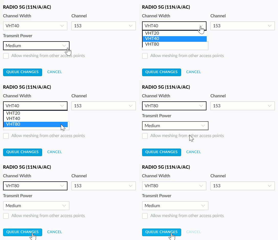
To properly test the maximum speed of a UniFi AP, switch to 80 MHz. 80 MHz channels are capable of more than double the peak speed of 40 MHz channels.NOTE: These settings only apply to 5GHz. We do not recommend that channel width be increased from 20 MHz on 2.4GHz as this will often cause worse performance. 

To change AP to use 80MHz channel width, go to Devices > Click on AP to open Properties Panel > Radios RADIO 5G (11N/A/AC), Change Channel Width from VHT40 to VHT80, click Queue Changes, then Apply Changes. 

2018-11-30_21-57-20.gif


Summary: If using a small number of APs, switch 5GHz channel width on APs to 80 MHz for greater peak throughput. In larger environments, note that 40 or 20 MHz channel width is recommended for performance but can limit peak throughput.

Interference/Channel Overlap

The single most potentially negative environmental factor for Wi-Fi performance and stability is wireless interference. Interference can come from external sources like other wireless networks, weather radar, etc. while internal interference can come from devices overlapping with each other on the same channel. 

By default, UniFi Devices are set up with auto channel assignments, but this is something you will want to adjust for your deployment if there are concerns about speed/performance. 

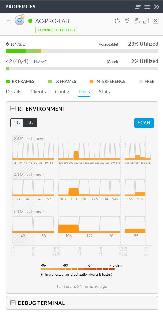
It is recommended that a full site survey be performed for high-density/high-priority Wi-Fi deployments. If that has not been done or the site doesn’t warrant it, the Network application can help you find a better channel assignment for your APs by performing an RF scan. 

To do this, go to Devices > Click on AP to open Properties Panel Tools > RF Environment and click ScanUser Tips:Running an RF Scan will disconnect any wireless clients currently connected to the AP. Do not run during peak hours if this is a concern. Suggested Channel Settings: 2.4GHz:
Channel width: HT20
Chanel: 1/6/11 Choose one of these channels, an RF scan will help you choose the cleanest one.Transmit Power: Medium5GHz:
Channel width: VHT40 
Optional VHT80/VHT160  (It will increase speeds but might cause more interference.)
Chanel: 36/44 | Optional (149/157) 
Choose one of these channels, an RF scan will help you choose the cleanest one. 
Avoid using DFS Channels unless you understand DFS logic.  (DFS Alerts will cause interruptions) 
Transmit Power: Medium (High)You could also modify your DTIM Periods if you have more modern devices on the network.
Settings > Wireless Network > SSID > 802.11 Rate And Beacon Controls
DITM 2G Period: 3
DITM 5G Period: 3

This scan will take 5-10 minutes and will populate the 2.4GHz channels first and then 5 GHz channels will subsequently be updated.

Once your RF scan is finished, select 5G and you’ll see a list of channels arranged by channel width and how much each channel is being utilized. Select a channel that appears to have the least noise on it and assign your AP to this channel.

To do this go to Devices > Click AP to select it and open Properties Panel > Properties > Radios RADIO 5G (11N/A/AC), and choose the desired channel. 

If using multiple APs, make sure that each AP does not share the same channel as a nearby AP, and avoid having channels that are adjacent to each other as this can also cause interference. 

pasted_image_0__1_.png

Summary: Interference/channel overlap can cause performance to decline. To make sure speed test results are not being impacted by interference, make sure APs are assigned to the optimal channel and not sharing or adjacent to the channel of any nearby APs.

Signal Quality

Another factor that can strongly influence Wi-Fi speed is the signal quality between AP and client device. As clients get further away from an access point and the signal gets weaker, to ensure stability/offer the best possible performance, the AP will lower the rate of the data transfer to compensate. 

When testing peak throughput, be sure to be standing close enough to the AP without obstructions and make sure the client signal strength is close to the maximum of 99%. If your client devices consistently have poor signal strength on 5GHz try increasing Transmit Power on 5GHz. 

To increase TX power on 5GHz, go to device configuration > Radios Radio 5G (11N/A/AC), and only select “High” from the dropbox under Transmit PowerNOTE: Increasing transmit power on devices can have undesired effects, especially in a very high density environment. Consider starting on High or Auto and only reducing to Medium as needed on a per-AP basis.

Summary: When testing throughput make sure to consider the signal strength between the device and AP, you can find this under the Clients tab in the Network application. If the range on 5GHz is very low, consider increasing Transmit Power on the AP’s 5GHz radio. 

Inconsistent/Inaccurate Speedtest Methods

Another cause for poor speed test performance is inconsistent or inaccurate data. When comparing across devices, make sure to use the same speed test method as different speed test apps can vary wildly. 

While UniFi does include a speed test, the results are often far lower than reality, especially since UniFi’s available speed test servers are limited and results are very sensitive to the proximity of the speed test server. Try using a popular speed test app or website to test to check your UniFi results. Be sure to test multiple times and do not rely on assumptions or past data to inform your comparison.

If you wish to most accurately assess Wi-Fi speed alone and rule out other factors, try performing an iPerf test between a wired and wireless client/between two wireless clients. iPerf only measures bandwidth between two devices on your network. Note that iPerf can still be limited by the syntax you can use, the number of streams, packet size, etc. so make sure you understand what you’re doing before using iPerf. 

Summary: Speedtest results are often inaccurate. Make sure to use consistent speed test methods when comparing between devices, wired vs. wireless, etc. Confirm/test using multiple platforms. UniFi speed tests are often less accurate than other more popular speed test apps

Client-specific Issues & Limitations

When benchmarking Wi-Fi, it’s important to also compare across devices to ensure that the client itself isn’t limiting performance. Factors like client CPU utilization, network card driver, Wi-Fi specs, software, all can influence speed test results. 

Make sure to test with multiple devices. To truly measure peak throughput you must test a device that matches the capabilities of the UniFi AP. For instance, if you are testing with a device check the manufacturer specifications to see how many streams the 5GHz antenna supports i.e. Apple iPhone 7 is 2×2, UAP-AC-PRO has 3×3 5GHz radio, thus this iPhone will limit peak throughput. 

If a performance issue with Wi-Fi is isolated to one device, or multiple devices running the same software version, this will almost always point to a problem with the device/software. UniFi doesn’t change how it functions for each variety of client device. Try performing a web search to find other users experiencing similar issues with the same device on other vendor products. 

Keep in mind that declined performance on a single device isn’t a sign of a malfunctioning AP. UniFi APs are backwards compatible with older client devices and the fact that devices are able to connect with their older hardware is a sign the AP is working as designed. 

Summary: Test multiple client devices when benchmarking Wi-Fi performance. Client-specific issues are common but are largely unrelated to AP configuration/hardware.

Additional Steps

After reviewing each of the previous steps, if the issue does not appear to be resolved, check out this article for some further suggestions to troubleshoot wireless performance.

If you’d like to get suggestions from other UniFi administrators, feel free to post on our community.

For issues that point to an issue with UniFi devices/software with respect to wireless performance, feel free to reach out to UniFi support. Please note that the UniFi support team is not able to optimize networks for customers and will not be able to assist with performance issues that are cosmetic in nature or do not indicate an actual UniFi performance issue i.e. improving speed test results from 400 Mbps to 600 Mbps.

Source :
https://help.ui.com/hc/en-us/articles/360012947634-UniFi-Troubleshooting-Slow-Wi-Fi-Speeds-

Ubiquiti UniFi Network – Troubleshooting Wireless Uplinks

You can wirelessly adopt access points to your UniFi Network. This allows you to extend your coverage without adding cabling in hard-to-reach areas. When within range of your already-adopted access points, simply connect a new access point to power and it will appear as ready for adoption in the Network application.

General troubleshooting

Wireless UAP does not appear for adoption

1. Verify that the UAP is powering properly and is ready for adoption (steady white LED).

2. Connect it via Ethernet cable to your network and wait for it to appear for adoption. If it still won’t appear while connected, please see our general adoption troubleshooting steps.

3. Update to the current firmware version if an upgrade is available.

4. Once the UAP is adopted and running the newest version available, disconnect it from the wired LAN, and wait a few minutes while it connects wirelessly. After that, you may disconnect it from power to move it to its final position. Once it powers up again, the UniFi Network application will recognize it and start broadcasting the network’s WiFi through your wireless UAP.

The UAP is adopted but it will not work when moved to wireless networks

1. Verify that the UAP is receiving enough power from the PoE injector. The LED must be a steady blue. Take a look at the UAP’s datasheet to verify power requirements.

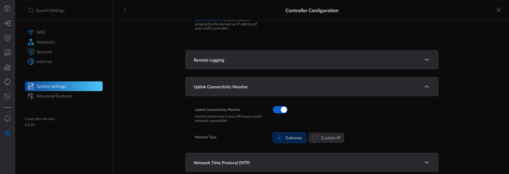
2. Verify that the Uplink Connectivity Monitor is enabled within Settings > System Settings > Controller Configuration > Uplink Connectivity Monitor.

uplink-connectivity-monitor.png

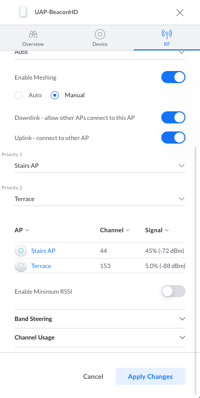
3. Verify that there is at least one wired UAP to act as an uplink and that Enable Meshing is turned on within the UAP’s properties panel > RF > Enable Meshing. And that the meshing configuration is set to Auto; or if set to Manual, that Downlink is enabled.

manual-meshing.downlink-enabled.png

Wireless uplink requirements

  • At least one wired access point to serve as the uplink UAP
  • A power source (i.e PoE injector) for the wireless UAP (downlink UAP)
  • (Recommended) Newest firmware and Network application versions.

Note: The wireless adoption process takes longer than the wired one; expect to wait a little longer for access point detection and for the adoption process to complete.

Modifying existing wireless uplink connections

You can design the topology to your liking by configuring how the wirelessly connected UAPs are linked. To change a UAP’s uplink:

  1. Select the UAP from the UniFi Devices section to open its properties panel.
  2. Go to the RF tab and select Manual under the Enable Meshing toggle. If the Enable Meshing option is not turned on, do so now to expose the wireless uplink settings.
  3. Select which UAP your wireless UAP will connect to (uplink).

Additionally, you can stipulate the uplink priority to define to which uplink your UAP will connect to if there is service degradation or if its current uplink goes offline. Use the Priority dropdown menus to select from the available uplinks.

pp.rf.manual-meshing.png

Frequently Asked Questions

Can a wireless UAP be the uplink to another wireless UAP?

Yes. This is known as a multi-hop wireless uplink and is supported by UniFi, as long as there is one wired access point to provide the first “hop”. Keep in mind that each wireless uplink will suffer service degradation, so this should only be done when necessary.

Can I connect older UAPs wirelessly?

Yes, you just need to make sure to configure them correctly. Some older UAPs only broadcast on a single band (2.4GHz) and will not work the same as newer models. The following older generation UAPs do support wireless uplink on the band they operate on and do not support multi-hop: UAP, UAP-LR, UAP-PRO, UAP-Outdoor, UAP-Outdoor+, UAP-Outdoor5, UAP-IW.

UAP-AC and UAP-AC-Outdoor do not support wireless uplink or multi-hop.

If you have a UAP that does support wireless uplinking and it is still not working, make sure to take the following into account:

Dual band uplink UAP to dual band downlink UAP: will uplink on 5GHz.
Dual band uplink UAP to single band downlink UAP: will uplink on the supported frequency of the single band model.
Single band uplink UAP to single band downlink UAP: will uplink, as long as the same band is supported on both sides of the link.
Single band (2.4GHz only models) uplink UAP to dual band downlink AP will not be able to uplink.

If you have several wired UAPs, these should have assigned channels that are different and do not overlap with other UAP channels to minimize interference.

  • If using all dual band UAPs
    • Set the wired UAP (uplink UAP) to static on 5GHz and to a static on 2.4GHz (1, 6 or 11 making sure it’s not a band also set for any of the other UAPs). Leave the wireless UAP (downlink UAP) set to Auto on the 5GHz radio and set a static channel on 2.4GHz not shared by others.
  • If using all single band UAPs
    • Set the wired UAP (uplink UAP) to a static channel on 2.4GHz. Leave the wireless UAP (downlink UAP) set to Auto on 2.4GHz. 
  • If using a dual band UAP as the uplink and single band UAP as the downlink
    • Set the wired UAP (uplink) to a static channel on 2.4GHz. Leave the wireless UAP (downlink) set to Auto.

      Source :
      https://help.ui.com/hc/en-us/articles/115002262328-UniFi-Network-Troubleshooting-Wireless-Uplinks

Ubiquiti UniFi – USG/UDM: Port Forwarding Configuration and Troubleshooting

With UniFi Network you can forward UDP and TCP ports to an internal LAN device using the Port Forwarding feature on the Dream Machine (UDM and UDM Pro) and USG models.

Requirements

  • Applicable to the latest firmware on all UDM and USG models.
  • The Port Forwarding feature is designed to only work on WAN1 on the USG models, but it can use both WAN1 and WAN2 on the UDM-Pro.
  • It is necessary to manually configure a Destination NAT (DNAT) + WAN firewall rule(s) to forward ports on the WAN2 interface on the USG models, see the section below.

Frequently Asked Questions (FAQ)

Do I need to manually create firewall rules for Port Forwarding?Can I forward ports on the WAN2 interface of the UDM/USG?How does the Port Forwarding feature interact with UPnP?Do I need to manually configure Hairpin NAT?Can I limit which remote devices are allowed to use the forwarded ports? My Port Forwarding rule does not work, what should I do?

Configuring a Port Forwarding Rule

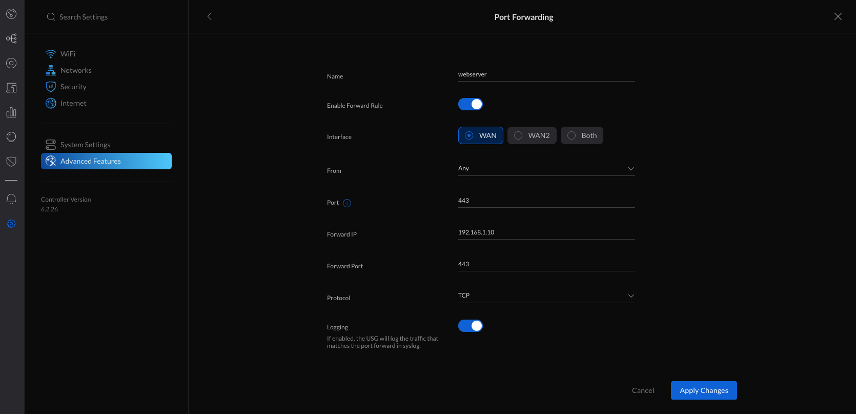
1. Navigate to Settings > Advanced Features > Advanced Gateway Settings and create new port forwarding.

2. Fill in the settings:

  • Name: webserver
  • Enable Forward Rule: turn this on when ready to activate this rule
  • Interface: WAN / WAN2 / Both (UDM Pro only)
  • From: Anywhere or Limited
  • Port: 443
  • Forward IP: 192.168.1.10
  • Forward Port: 443
  • Protocol: TCP
  • Logging: Optional
From:The clients on the Internet that are allowed to use the Port Forwarding rule. Set to Anywhere by default, meaning all hosts. It is possible to limit the allowed hosts by specifying an IP address (for example 198.51.100.1) or subnet range (for example 198.51.100.0/24). 
Port:The WAN port that the clients on the Internet connect to, for example 443. This does not need to match the port used on the internal LAN host. You can forward TCP port 10443 to TCP port 443, for example.
Forward IP:The IP address used by the internal LAN host, for example 192.168.1.10.
Forward Port:The port used by the internal LAN host, for example TCP port 443.
port-forwarding.wan.png

3. Apply the changes.

Note: On the USG models, it is necessary to manually configure a Destination NAT (DNAT) + WAN firewall rule to forward ports on the WAN2 interface, see the section below.

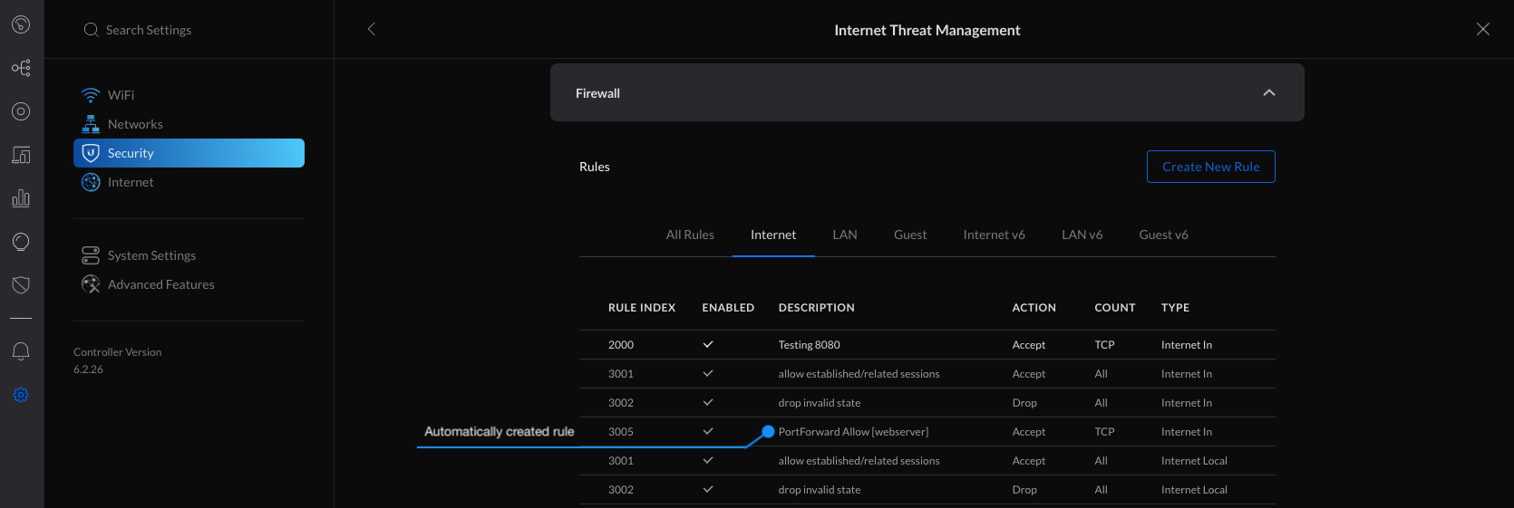
4. The firewall rule(s) needed for the new Port Forwarding rule you created are automatically added.

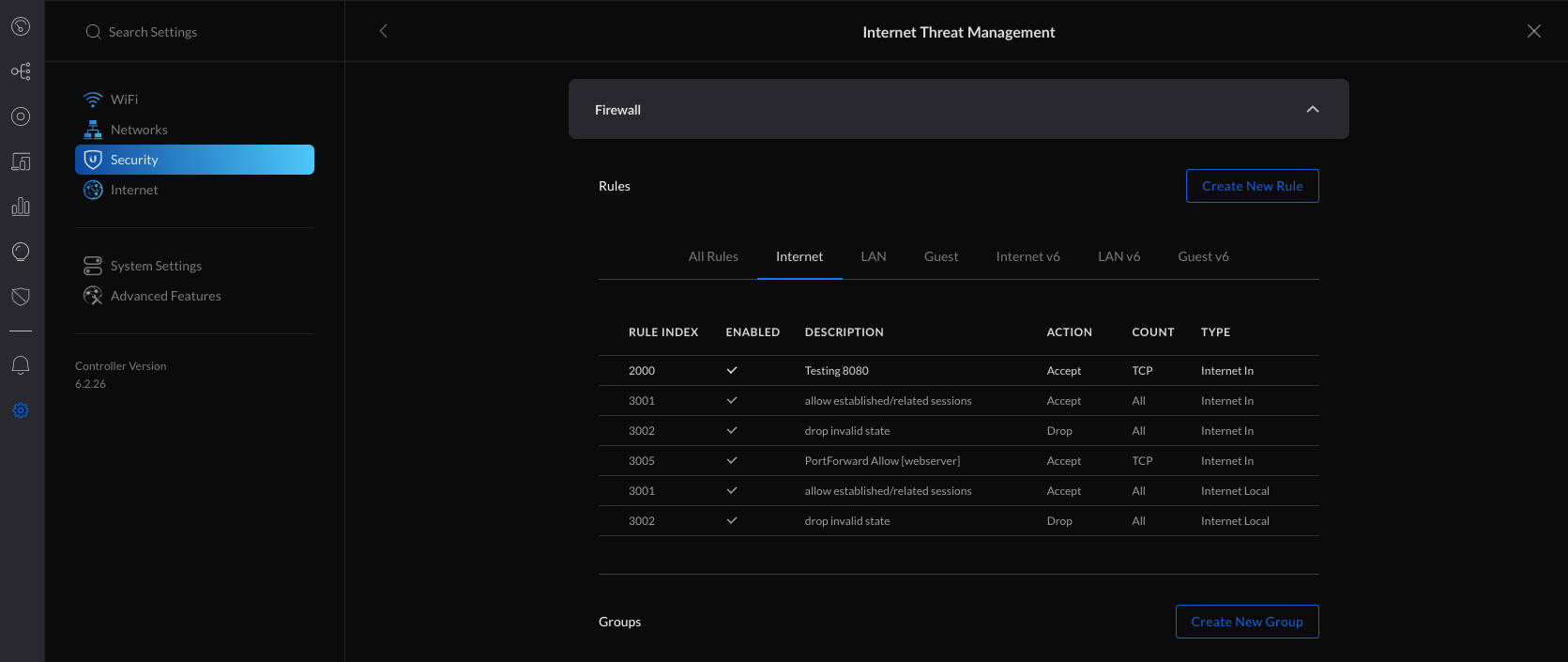
5. You can verify the automatically created rules in the Settings > Security > Internet Threat Management > Firewall > Internet section.

firewall.internet.automatic.rule.png

USG/USG-Pro: Forwarding Ports on WAN2 using Destination NAT

ATTENTION: This is an advanced configuration that requires creating and modifying the config.gateway.json file. See the UniFi – USG/USG-Pro: Advanced Configuration Using JSON article for more information on using the JSON file.

Follow the steps below to forward ports on the WAN2 interface of the USG models. It is necessary to manually create a Destination NAT (DNAT) rule using the Command Line Interface (CLI) and a custom Firewall Rule using the UniFi Network application. Afterwards, the config.gateway.json file needs to be created or updated to incorporate the custom configuration into UniFi Network.

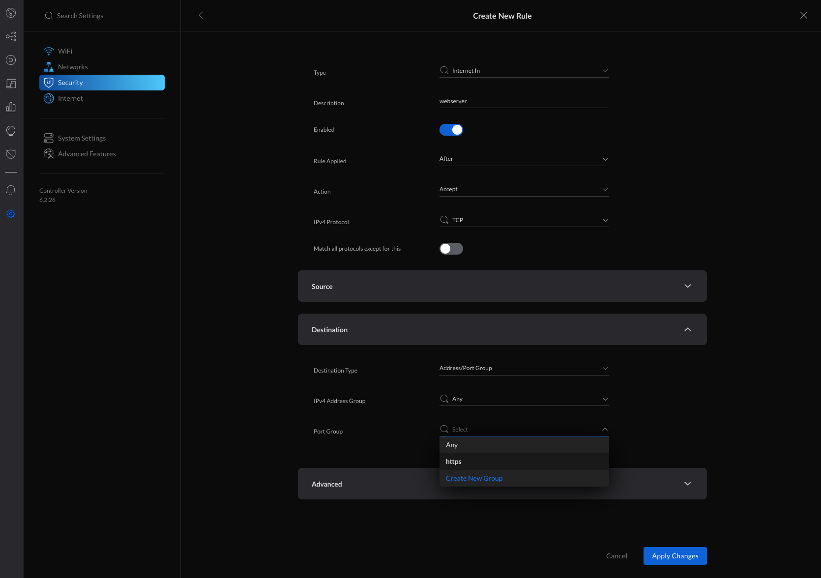
1. Begin by creating a new custom Firewall Rule within  Settings > Security > Internet Threat Management > Firewall > Internet section.

2. Create a new Firewall Port Group by clicking Create New Group.

firewall.internet.png

3. Fill in the information and specify the port that needs to be allowed through the firewall (443 in this example) and apply changes.

  • Name: https
  • Type: Port Group
  • Port: 443
firewall.create-new-group.png

4. Navigate to    Settings > Security > Internet Threat Management > Firewall > Internet and create new rule.

5. Fill in the information, selecting the previously created Port Group and apply changes.

  • General
    • Type: Internet In
    • Description: webserver
    • Enabled: turned on when ready to take this rule live
    • Rule Applied: After (after predefined rules)
    • Action: Accept
    • IPv4 Protocol: TCP
    • Match all protocols except for this: disabled
  • Source: Optional
  • Destination
    • Destination Type: Address/Port Group
    • IPv4 Address Group: Any
    • Port Group: https (select from any previously created firewall port groups)
  • Advanced: Optional
firewall.create-new-rule.png

6. The next step is to access the USG using the Command Line Interface (CLI) and add a custom Destination NAT (DNAT) rule. SSH access to your devices must be enabled within    Settings > System Settings > Controller Configuration > Device SSH Authentication.

7. Connect to the USG via SSH.SSH using WindowsSSH using macOS

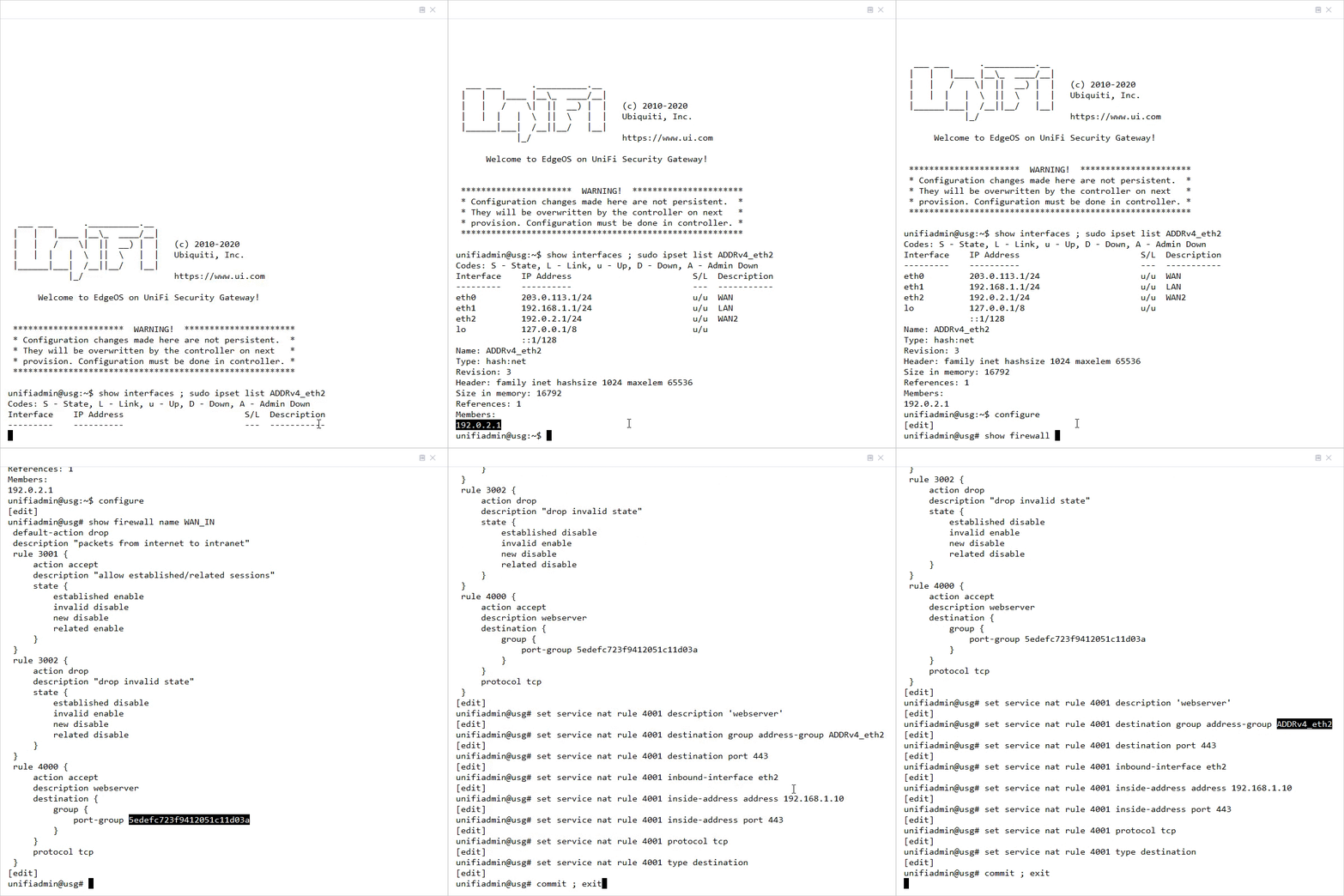
8. Verify that the WAN2 interface is UP and that it is assigned an IP address by running the following command: 

show interfaces ; sudo ipset list ADDRv4_eth2

Click to copy

unifiadmin@usg:~$ show interfaces 
Codes: S - State, L - Link, u - Up, D - Down, A - Admin Down
Interface    IP Address                        S/L  Description                 
---------    ----------                        ---  -----------                 
eth0         203.0.113.1/24                    u/u  WAN                         
eth1         192.168.1.1/24                    u/u  LAN                         
eth2         192.0.2.1/24                      u/u  WAN2                           
lo           127.0.0.1/8                       u/u                              
             ::1/128                          
unifiadmin@usg:~$ sudo ipset list ADDRv4_eth2
Name: ADDRv4_eth2
Type: hash:net
Revision: 3
Header: family inet hashsize 1024 maxelem 65536
Size in memory: 16792
References: 1
Members:
192.0.2.1

NOTE: The ADDRv4_eth2 is a special address group that automatically uses the IP address that is assigned to the eth2 interface. On the USG-Pro, the WAN2 interface uses eth3 instead and thus the address group will be ADDRv4_eth3.

9. Enter configuration mode by typing configure and hitting enter.

10. Add the Destination NAT rule for the WAN2 interface of the USG/USG-Pro (replace eth2 with eth3 for the USG-Pro):

set service nat rule 4001 description 'webserver'
set service nat rule 4001 destination group address-group ADDRv4_eth2
set service nat rule 4001 destination port 443
set service nat rule 4001 inbound-interface eth2
set service nat rule 4001 inside-address address 192.168.1.10
set service nat rule 4001 inside-address port 443
set service nat rule 4001 protocol tcp
set service nat rule 4001 type destination

Click to copy

11. Commit the changes and exit back to operational mode by typing commit ; exit and hitting enter.

This is an example of the process:

custom-dnat-rule.gif

12. Use the mca-ctrl -t dump-cfg command to display the entire config in JSON format:

mca-ctrl -t dump-cfg

Click to copy

13. The Destination NAT section of the configuration in JSON format can then be used in the config.gateway.json file.

{
       "service": {
                "nat": {
                        "rule": {
                                "4001": {
                                        "description": "webserver",
                                        "destination": {
                                                "group": {
                                                        "address-group": "ADDRv4_eth2"
                                                },
                                                "port": "443"
                                        },
                                        "inbound-interface": "eth2",
                                        "inside-address": {
                                                "address": "192.168.1.10",
                                                "port": "443"
                                        },
                                        "protocol": "tcp",
                                        "type": "destination"
                                }
                        }
                }
       }
}

Click to copy

14. See the UniFi – USG/USG-Pro: Advanced Configuration Using JSON article for more information on how to create and modify the config.gateway.json file.

Troubleshooting Port Forwarding Issues

Refer to the troubleshooting steps below if the Port Forwarding or custom Destination NAT rule is not working. Either of the following options can be the cause:   Possible Cause #1 – The USG/UDM is located behind NAT and does not have a public IP address.   Possible Cause #2 – The UDM/USG is already forwarding the port to another device or has UPnP enabled.   Possible Cause #3 – The traffic from the Internet clients is not reaching the WAN interface of the UDM/USG.  Possible Cause #4 – The LAN host is not allowing the port through the local firewall or does not have the correct route configured. 

Source :
https://help.ui.com/hc/en-us/articles/235723207-UniFi-USG-UDM-Port-Forwarding-Configuration-and-Troubleshooting

Ubiquiti UniFi – Layer 3 Adoption for Remote UniFi Network Applications

Layer 3 adoption is the process of adopting a UniFi device to a remote UniFi Network application.

You might use Layer 3 adoption for applications located in the cloud (e.g. on Amazon EC2) or NOC.

For regular device adoption, see UniFi – Device adoption.

Overview

In many deployments where it’s not possible to have the UniFi Network host running on-premise, you can run the UniFi Network application in the Cloud or your NOC. For example, for a large-scale project with many devices there are a few possible methods for the adoption of devices:

  • Take a laptop to the device’s site to perform adoption via Chrome browser (easiest method).
  • When you’re at the site, open a browser and navigate to Cloud: either the UniFi Remote Access Portal or the UniFi Network application (when launched using Cloud).
  • Create a virtual application instance on Amazon EC2.
  • Either configure the DHCP server or DNS server.

Initial setup

Please make sure you’re familiar with how a regular L2 adoption on UniFi works (where the devices and UniFi Network application are on the same network) before attempting L3 (remote) adoption. Also, remember that in order to adopt, the following conditions must be true in order to have internet access and also have access to the router from within the network (locally):

1. WAN port connected to the Internet.
2. LAN port connected locally to access management features on the router (USG or third party).

UniFi APs have a default inform URL http://unifi:8080/inform. Thus, the purpose of using DHCP option 43 or DNS is to allow the AP to know the IP of the UniFi Network application host.

If you encounter discovery issues please use the UniFi – Troubleshooting Device Adoption article to help you troubleshoot the issue.

After installing the Discovery tool plugin (freely available in Chrome Web Store) on a computer running Chrome browser, any locally-available, unmanaged UniFi Devices (i.e., same L2 network as your computer) will appear as “Pending Adoption” in the UniFi Cloud Access Portal as well as your UniFi Network application itself (in the Devices section in both cases). To access the application remotely Remote Access will have to be enabled.

Via UniFi OS

1. Go to https://unifi.ui.com and login with your Ubiquiti SSO credentials.

2. Navigate to the Devices section.

3. The device to be adopted will appear as ready to be adopted. Click Adopt.

unifi-devices.wireless.adoption.png

Via the UniFi Remote Access Portal

1. Go to https://network.unifi.ui.com/ and log in with your Ubiquiti SSO credentials.

2. Go to the Devices section and locate the model with the Pending Adoption status. Click ADOPT.

3. In the Adopt window that will appear, select the UniFi Network host and the site that will be adopting the device (for multi-site hosts) and click Adopt.

Via the UniFi Network application

1. Launch UniFi Network, go to the Devices section, find the device that is to be adopted with the status “Pending Adoption” and click Adopt under Actions.

DNS

You’ll need to configure your DNS server to resolve ‘unifi’ to your UniFi Network host’s IP address. Make sure that the device can resolve the UniFi Network domain name. For example, if you are setting http://XYZ:8080/inform, then ping from the device to determine if XYZ is resolvable/reachable. Or you may also use FQDN for the application inform URL: http://FQDN:8080/inform

Troubleshooting: Device (with static IP) fails to connect to the L3 UniFi Network application

  • When configuring a device from DHCP to static in the UniFi Network application, make sure you have put the IP of DNS. If not, then the device cannot contact DNS to resolve UniFi Network’s domain name.
  • If the device has been reset, make sure that you have “informed” the device twice (using the Discovery Utility) about the UniFi Network application’s location. See steps in the section above.

DHCP Option 43

If using Ubiquiti’s EdgeMAX routers, then DHCP option 43 can be done by just entering the IP address of the UniFi Network host in the “unifi” field on the DHCP-server.NOTE: The UniFi Security Gateway (USG) will not use DHCP option 43 to add the UniFi Network application location when obtaining a DHCP lease on the WAN interface.

To use DHCP option 43 you’ll need to configure your DHCP Server. We provide some third party examples below, but please refer to the manufacturer’s support documentation for up to date instructions. For example:

Linux’s ISC DHCP server: dhcpd.conf

# ...
option space ubnt;
option ubnt.unifi-address code 1 = ip-address;

class "ubnt" {
        match if substring (option vendor-class-identifier, 0, 4) = "ubnt";
        option vendor-class-identifier "ubnt";
        vendor-option-space ubnt;
}

subnet 10.10.10.0 netmask 255.255.255.0 {
        range 10.10.10.100 10.10.10.160;
        option ubnt.unifi-address 201.10.7.31;  ### UniFi Network host IP ###
        option routers 10.10.10.2;
        option broadcast-address 10.10.10.255;
        option domain-name-servers 168.95.1.1, 8.8.8.8;
        # ...
}

Cisco CLI

# assuming your UniFi is at 192.168.3.10
ip dhcp pool <pool name>
network <ip network> <netmask>
default-router <default-router IP address>
dns-server <dns server IP address>
option 43 hex 0104C0A8030A # 192.168.3.10 -> CO A8 03 0A

# Why 0104C0A8030A ?
#
# 01: suboption
# 04: length of the payload (must be 4)
# C0A8030A: 192.168.3.10

Mikrotik CLI

/ip dhcp-server option add code=43 name=unifi value=0x0104C0A8030A
/ip dhcp-server network set 0 dhcp-option=unifi

# Why 0104C0A8030A ?
#
# 01: suboption
# 04: length of the payload (must be 4)
# C0A8030A: 192.168.3.10

User Tip: Find more DHCP Option 43 instructions in the User Notes & Tips section.

SSH

If you can SSH into the device, it’s possible to do L3 adoption via CLI command:

1. Make sure the device is running updated firmware. See this guide: UniFi – Changing the Firmware of a UniFi Device.

2. Make sure the device is in the factory default state. If it’s not, run the following command:

sudo syswrapper.sh restore-default

3. SSH into the device and type the following and hit enter, substituting “ip-of-host” with the IP address of the host of the UniFi Network application:

set-inform http://ip-of-host:8080/inform

4. After issuing the set-inform, the UniFi device will show up for adoption in the Devices section of UniFi Network. Once you click Adopt, the device will appear to go offline or have the status of “Adopting” then proceed to “Provision” and “Connected”.

Source :
https://help.ui.com/hc/en-us/articles/204909754-UniFi-Layer-3-Adoption-for-Remote-UniFi-Network-Applications

Ubiquiti UniFi – How to Create and Restore a Backup

This article describes how to generate a backup of the UniFi Network application as well as how to restore it. This article does not cover the Auto Backup feature. You may see this article for more information on that subject: UniFi – How to Configure Auto Backup.

Note: This article is applicable to current UniFi Network application versions. Instructions on backups for older versions can be found at the bottom of this page in the “Method 3: Restoring from the /data Directory” section. As always, we suggest you update to the newest software and firmware available.

Introduction

The UniFi backup file has an extension of .unifi and contains the settings and the database for the UniFi Network application. The database is not included in a “settings only” backup. The backup also includes the config.propertiessystem.properties and config.gateway.json advanced configuration files, maps, and any customized files in a site’s portal folder. You can download a backup at any time from the Network application following the steps below.

Generate a New Backup

To generate a new UniFi backup file (.unifi), on your UniFi OS Console:

  1. Access and log into your UniFi OS Console at unifi.ui.com or locally via its IP address.
  2. Go to System Settings Advanced and enable the Back up Device toggle if disabled.
  3. Click Download to download your backup file. 

You can also use the Backup Scheduler to schedule creating a backup at a certain occurrence and time. 

Screenshot_2021-05-05_at_14.13.24.png

Restore a Backup

Method 1: Restore in the UniFi Network application

To restore a backup you have previously generated:

  1. Access and log into your UniFi OS Console at unifi.ui.com or locally via its IP address.
  2. Go to System Settings > Advanced and click the Restore in the “Restore Device” section.
  3. Select the necessary settings in the Restore Backup pop-up window:
    1. Select the device on the Device Selection drop-down field which you will restore from a backup.
    2. Confirm that you will restore your device either to the latest backup or select another backup from a list by clicking on the here text button.
    3. Enter your SSO account password and click Restore to begin the restoring process. 

Once you confirm, the backup restoration will begin. This process takes a few minutes. Do not disconnect while the application is working on this. Once the new backup is restored, the application will restart.

Method 2: Restore in the UniFi Startup Wizard

If beginning a new installation, it will be easier to just use the option of restore from a previous backup as soon as the UniFi Startup Wizard launches, and select your .unf file.

Method 3: Restore from the /data Directory

Note: This method is for older Network application versions and is not recommended. For security reasons, we suggest always upgrading to the newest release available. If you still wish to use this method, click on the link below.

Click here to display Method 3: Restoring from the /data Directory.

Change the Inform Address for All Devices in the Network application

ATTENTION:Use this method with caution. After completing these steps the devices will be setting the inform address to the new IP address or FQDN specified.  

It may be desired to change the IP address or FQDN that the UniFi devices on multiple sites are reporting to after an application restore. This process is typically used when migrating from one functional UniFi OS Console to a new install.

  1. Download a backup file from the current UniFi OS Console.
  2. Install the Network application on the new UniFi OS Console. 
  3. Restore the backup that came from step 1 and let the upload process finish.
  4. Log into the new UniFi OS Console. 
  5. On the old UniFi OS Console’s Network application, go to Settings > System > Other Configuration and enable the Override Inform Host toggle.
  6. Type in the new UniFi OS Console’s Hostname or IP Address field. 
  7. Select Apply Changes.

After the changes are applied the old UniFi OS Console will send the configuration to adopted and currently connected devices stating the inform host is now what was input in the Hostname or IP Address field.

If this was performed correctly, the devices should start appearing in the new UniFi OS Console. This should not take longer than 5 minutes but can be longer depending on the number of devices, the physical proximity of the devices, and new UniFi OS Console’s technical specification.

Source :
https://help.ui.com/hc/en-us/articles/204952144-UniFi-How-to-Create-and-Restore-a-Backup

GoDaddy Breached – Plaintext Passwords – 1.2M Affected

This morning, GoDaddy disclosed that an unknown attacker had gained unauthorized access to the system used to provision the company’s Managed WordPress sites, impacting up to 1.2 million of their WordPress customers. Note that this number does not include the number of customers of those websites that are affected by this breach, and some GoDaddy customers have multiple Managed WordPress sites in their accounts.

According to the report filed by GoDaddy with the SEC [1], the attacker initially gained access via a compromised password on September 6, 2021, and was discovered on November 17, 2021 at which point their access was revoked. While the company took immediate action to mitigate the damage, the attacker had more than two months to establish persistence, so anyone currently using GoDaddy’s Managed WordPress product should assume compromise until they can confirm that is not the case.

It appears that GoDaddy was storing sFTP credentials either as plaintext, or in a format that could be reversed into plaintext. They did this rather than using a salted hash, or a public key, both of which are considered industry best practices for sFTP. This allowed an attacker direct access to password credentials without the need to crack them.

According to their SEC filing: “For active customers, sFTP and database usernames and passwords were exposed.

We attempted to contact GoDaddy for comment and to confirm our findings, but they did not immediately respond to our requests for comment.

What did the attacker have access to?

The SEC filing indicates that the attacker had access to user email addresses and customer numbers, the original WordPress Admin password that was set at the time of provisioning, and SSL private keys. All of these could be of use to an attacker, but one item, in particular, stands out:

During the period from September 6, 2021, to November 17, 2021, the sFTP and database usernames and passwords of active customers were accessible to the attacker. 

GoDaddy stored sFTP passwords in such a way that the plaintext versions of the passwords could be retrieved, rather than storing salted hashes of these passwords, or providing public key authentication, which are both industry best practices.

We confirmed this by accessing the user interface for GoDaddy Managed Hosting and were able to view our own password, shown in the screenshot below. When using public-key authentication or salted hashes, it is not possible to view your own password like this because the hosting provider simply does not have it.

You’ll also note that the system is using port 22, which is Secure File Transfer Protocol. There are several kinds of sFTP, and this confirms that they’re using sFTP via SSH, which is encrypted, and designed to be one of the most secure ways to transfer files. Storing plaintext passwords, or passwords in a reversible format for what is essentially an SSH connection is not a best practice.

GoDaddy appears to acknowledge that they stored database passwords as plaintext or in a reversible format. These are also retrievable via their user interface. Unfortunately storing database passwords as plaintext is quite normal in a WordPress setting, where the database password is stored in the wp-config.php file as text. What is more surprising, in this breach, is that the password that provides read/write access to the entire filesystem via sFTP is stored as plaintext.

What could an attacker do with this information?

While the SEC filing emphasizes the potential phishing risk posed by exposed email addresses and customer numbers, the risk posed by this is minimal compared to the potential impact of exposed sFTP and database passwords.

Although GoDaddy immediately reset the sFTP and Database passwords of all the impacted sites, the attacker had nearly a month and a half of access during which they could have taken over these sites by uploading malware or adding a malicious administrative user. Doing so would allow the attacker to maintain persistence and retain control of the sites even after the passwords were changed.

Additionally, with database access, the attacker would have had access to sensitive information, including website customer PII (personally identifiable information) stored on the databases of the impacted sites, and may have been able to extract the contents of all impacted databases in full. This includes information such as the password hashes stored in the WordPress user accounts databases of affected sites, and customer information from e-Commerce sites.

An attacker could similarly gain control on sites that had not changed their default admin password, but it would be simpler for them to simply use their sFTP and database access to do so.

On sites where the SSL private key was exposed, it could be possible for an attacker to decrypt traffic using the stolen SSL private key, provided they could successfully perform a man-in-the-middle (MITM) attack that intercepts encrypted traffic between a site visitor and an affected site.

What should I do if I have a GoDaddy Managed WordPress site?

GoDaddy will be reaching out to impacted customers over the next few days. In the meantime, given the severity of the issue and the data the attacker had access to, we recommend that all Managed WordPress users assume that they have been breached and perform the following actions:

  • If you’re running an e-commerce site, or store PII (personally identifiable information), and GoDaddy verifies that you have been breached, you may be required to notify your customers of the breach. Please research what the regulatory requirements are in your jurisdiction, and make sure you comply with those requirements.
  • Change all of your WordPress passwords, and if possible force a password reset for your WordPress users or customers. As the attacker had access to the password hashes in every impacted WordPress database, they could potentially crack and use those passwords on the impacted sites.
  • Change any reused passwords and advise your users or customers to do so as well. The attacker could potentially use credentials extracted from impacted sites to access any other services where the same password was used. For example, if one of your customers uses the same email and password on your site as they use for their Gmail account, that customer’s Gmail could be breached by the attacker once they crack that customer’s password.
  • Enable 2-factor authentication wherever possible. The Wordfence plugin provides this as a free feature for WordPress sites, and most other services provide an option for 2-factor authentication.
  • Check your site for unauthorized administrator accounts.
  • Scan your site for malware using a security scanner.
  • Check your site’s filesystem, including wp-content/plugins and wp-content/mu-plugins, for any unexpected plugins, or plugins that do not appear in the plugins menu, as it is possible to use legitimate plugins to maintain unauthorized access.
  • Be on the lookout for suspicious emails – phishing is still a risk, and an attacker could still use extracted emails and customer numbers to obtain further sensitive information from victims of this compromise.

Conclusion

The GoDaddy Managed WordPress data breach is likely to have far-reaching consequences. GoDaddy’s Managed WordPress offering makes up a significant portion of the WordPress ecosystem, and this affects not only site owners, but their customers. The SEC filing says that “Up to 1.2 million active and inactive Managed WordPress customers” were affected. Customers of those sites are most likely also affected, which makes the number of affected people much larger.

For the time being, anyone using GoDaddy’s Managed WordPress offering should assume their sites have been compromised until further information becomes available, and follow the steps we have provided in this article. We will update the article if more information becomes available.

References:

  1. GoDaddy SEC Report: https://www.sec.gov/Archives/edgar/data/1609711/000160971121000122/gddyblogpostnov222021.htm

Note: All product names, logos, and brands are property of their respective owners in the United States and/or other countries. All company, product, and service names used on this page are for identification purposes only. Use of these names, logos, and brands does not imply endorsement.

Source :
https://www.wordfence.com/blog/2021/11/godaddy-breach-plaintext-passwords/