Using Wireshark to Analyze and Troubleshoot Hyper-V Networking

Analyze traffic and uncover Hyper-V networking problems has never been easier

Networking problems frequently challenge administrators. Introducing a virtualized switch to the mix adds another layer of complexity and multiple failure points. We can use the popular Wireshark tool to analyze traffic and uncover problems.

Requirements for Success with Wireshark

First, you need the software. You can download Wireshark from Wireshark.org. The site includes substantial information and links to more. Due to the extensive depth of the tool, the value that you get from Wireshark depends directly on how well you’ve learned it. Ideally, you’d go through a guided course and practice on training captures. I understand that you might have more immediate needs. This article illustrates enough to get you started but expect to invest time in training and practice.

Second, you need a working knowledge of Ethernet frame structure. You do not need anything near expert level, but you won’t get far if you can’t make sense of what Wireshark reveals. We have an article series on basic networking that can get you started.

Remote Captures in Wireshark

Wireshark can capture information on remote systems. However, it includes more hints than details. I could not find any directions that I felt comfortable sharing. Fortunately, you have alternatives.

Wireshark will run on Windows Server. Because it relies on the Qt library for its graphical interface, you can run the entire program on a Core mode installation by manually starting “C:\Program Files\Wireshark\Wireshark.exe”. I have no objection to running Wireshark on a server. However, I do not like RDP or similar remote connections to servers. These technologies present a significant attack surface for malware and intruders. Use at your own risk.

During the Wireshark install, you can also select the TShark program, which gives you command-line access to captures. TShark works inside a PowerShell Remote session. That means that you can install TShark on a system that you want to capture “remotely”, output its capture to disk, and then import it into a management system. I will not spend much time on TShark in this article, but I will get you started.

TShark Fundamentals

First, install at least the TShark portion of Wireshark on the target server. That might require a remote desktop connection as Wireshark has no official support for remote or scripted installation. However, running “Wireshark-Win64-<VER>.exe /s” at a command prompt, (or via a script, or possibly even a remote session), should install the software with default options.

Second, open a remote PowerShell session to the server using credentials with administrative privileges on the target:

Connect-PSSession -ComputerName <SERVERNAME>

Alternatively, you can supply credentials at the point of entry:

Connect-PSSession -ComputerName <SERVERNAME> -Credential (Get-Credential)

Once you have your remote session, run Get-NetAdapter to retrieve a list of adapters on the remote server:

TShark Fundamentals

Locate the adapter(s) that host the Hyper-V virtual switch on the server and note the value(s) for ifIndex. In my case, I want interfaces 4 and 10. With that knowledge, initiate TShark. Tell it which interfaces to include in the capture and where to write an output file with the -i and -w switches, respectively. That looks something like this:

& ‘C:\Program Files\Wireshark\tshark.exe’ -i 4 -i 10 -w C:\Users\esadmin\Documents\cap.pcapng

You do need the leading ampersand. If you use tab completion for assistance in entering the path to TShark, PowerShell will insert it automatically.

Upon pressing [Enter], the capture starts and writes to the file. Most importantly, you need to know that pressing [CTRL]+[C] stops the capture. Because we did not specify a capture limit, it will run until we either cancel it or the remote system runs out of disk space. Less importantly, the TShark program does not generate all its console output in a way that PowerShell remote sessions can process. You will see some things that look like error messages and other things will not appear at all. Just remember how to start and stop the capture and you will get the expected capture file.

TShark allows you to restrict captures with limits and filters.

TShark allows you to restrict captures with limits and filters. I will leave learning about that to you. Start with tshark.exe –help. The instructions above will generate a capture file that, at worst, has more data than you want. Once you have that file, you can transfer it to your management workstation and use Wireshark to operate on it.

A Warning about Wireshark and Resources

Wireshark will write to capture files, but it defaults to keeping captured packets in memory unless told otherwise. When possible, only run captures for the time needed to gather the data relevant to the problem you want to solve. Take care to set limits on long-running captures to ensure that you do not consume all host memory or disk space. Remember that a full disk will cause any VMs on that disk to pause. Also, remember that Hyper-V prioritizes processes in the management operating system, so it will squeeze virtual machines as needed to provide CPU and memory resources to Wireshark.

Set capture limits from Wireshark’s main interface by clicking the Capture menu item on the menu bar and then clicking Options.

Wireshark will write to capture files

The Input tab allows you to select the adapters to watch and to define capture filters. The Output tab gives you options for writing to files. You can set finite capture limits on the Options tab that apply whether writing to memory or disk, along with some handy quality-of-life settings.

While we frequently want to capture all data so that we don’t miss environmental problems, you can greatly reduce capture size with capture filters. Unlike display filters, capture filters tell Wireshark to discard information without storing it. Use these cautiously; if you inadvertently throw out interesting frames, you’ll have to perform additional captures.

Finally, remember that 10GB and faster interfaces can already generate heavy CPU loads. Using Wireshark to capture and decipher frames costs that much more. Few systems drive their networking capabilities anywhere near their maximums but remain mindful.

Traffic Must Pass a Physical Adapter for Wireshark to Capture It

With the current way that the Hyper-V virtual switch projects into the management operating system, Wireshark cannot bind directly to it. Instead, we attach it to one or more physical adapters. This means that, at the management operating system level, Wireshark cannot intercept any traffic that never leaves the VMBus.

The VMBus limitation primarily impacts internal and private virtual switches. Without a physical adapter, you have few options. If you have an unused physical adapter, you could temporarily bind the virtual switch to it with Set-VMSwitch. If your host uses the older LBFO technology, you can add a team NIC in another VLAN and bind your virtual switch to that. Even with these alternatives, you will still miss anything that does not cross the bound adapter.

However, this should only present a problem in edge cases. Wireshark and TShark can operate just as well inside a virtual machine as they can in the management operating system. Wireshark does not distinguish between virtual and physical adapters. Set it to watch the virtual adapters involved in your communications chain, and you’ll see the traffic. If you can’t install either product inside a given virtual machine, you still have Hyper-V’s port mirroring feature.

Capturing All Virtual Switch Traffic

When you don’t know exactly what you’re looking for, which applies well when you don’t have much experience with network captures, just get everything. When you first open Wireshark, it will present all network adapters that it can operate with. Find the physical adapters that host your virtual switch and highlight them:

Capturing All Virtual Switch Traffic

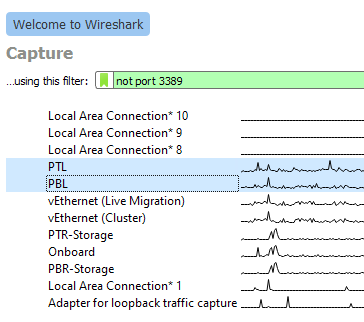
Remember that choosing anything that says “vEthernet” in its name binds to that virtual adapter, not the virtual switch. For switch monitoring, you must choose the physical adapter(s).

You can either right-click your selection and click Start Capture or you can click the blue shark icon at the left of Wireshark’s icon menu. If you made a mistake in adapter selection or just want to change it after the capture has started, select Options from the Capture menu:

click Start Capture

Once the capture starts. you should see a rapidly scrolling screen like the one below. If you’re working on a problem, reproduce it while the trace runs.

Once the capture starts. you should see a rapidly scrolling screen

Once the trace has captured enough information, click the red square button on the toolbar to end it. Regardless of your intentions, I recommend saving the file. It’s better to have a capture file that you don’t need than the opposite.

You can scan through the capture to look for anything that seems out of place or just to acclimate yourself to a network capture. If you’ve never used Wireshark before, the topmost pane shows a list of captured frames with some basic information about each. The middle pane tries to break the selected frame down into its individual components. Click on the triangle icon to the left of any item to drill down further. Wireshark uses “dissectors” to interpret frame components. Anything that it doesn’t recognize goes into the generic “Data” portion. The third pane shows a binary dump of the frame. If you click any part of that, the dissector pane will shift focus to that location.

Listings such as this allow you to peruse the activity crossing your virtual switch. You can investigate whatever interests you.

Exercise 1: Capturing Virtual Switch Traffic by Port

Tracing traffic by port can help you locate breaks in communication. It helps you to discover if messages that you expect to arrive on a virtual machine ever make it to the virtual switch at all. You can ensure that servers on virtual machines respond to clients as expected. You can watch for traffic coming from unexpected (potentially malicious) sources.

In my example exercise, I want to verify that my “primary” domain controller properly receives and responds to authentication traffic. For the most basic trace, I can set a display filter on a previously captured file or on an active trace with this format: tcp.port == 389:

Capturing Virtual Switch Traffic by Port

For thoroughness, I want to look at all traffic that a domain controller would utilize for authentication traffic. I can filter to multiple ports like this: tcp.port == 88 or tcp.port == 389 or tcp.port == 636 or tcp.port == 3268 or tcp.port == 3269

domain controller would utilize for authentication traffic

Pressing [Enter] or the white arrow with the blue background at the end of the filter field will update the display to show only frames that match the filter:

blue background at the end of the filter field

Scanning the filtered view, I see frames that it clearly identifies as LDAP and others that it marks only as TCP. When Wireshark cannot identify a frame, look to the Info column. In the third row of the screenshot, we see that it has marked the frame as [ACK]. That tells us that the frame contains an acknowledgement of a previously received frame.

If I want to find out what the frame acknowledged, I can right-click on the line item, hover over Conversation Filter, and choose one of the offered items. In this case, I don’t want to miss anything, so I choose Ethernet as the least specific filter:

Conversation Filter

In response, Wireshark pares down the display to only the items that belong to that particular “conversation”. Also, notice that it updated the display filter:

display filter

I know that 192.168.5.1 belongs to the domain controller of interest. I also know that 192.168.5.2 belongs to my “secondary” domain controller. Therefore, before I even performed any of these tasks, I could have guessed that these frames carry requests or updates that keep domain information synchronized. To confirm, I select the first frame in the conversation in the top pane. In the second pane, I find the Lightweight Directory Access Protocol section that indicates a dissector has come into play. In the bottom frame, I locate the highlighted information (remember that this matches whatever I selected in the middle frame):

Lightweight Directory Access Protocol

The frame appears to have something to do with DNS settings. I look at the same portion of the second frame:

The frame appears to have something to do with DNS settings

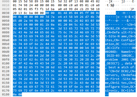
We already know that the third and final frame in the conversation is an ACK. So, we can surmise that 192.168.5.2 asked 192.168.5.1 about SVDC02 as a DNS server, got a NO_OBJECT result, and acknowledged receipt of the result. It appears that I may have some DNS troubleshooting to do.

However, I was interested in authentication traffic. We learned that the tracked conversation dealt with DNS servers. I can return to my previous filtered view by clicking the drop-down arrow at the end of the filter line and choosing the filter that I want to see again:

We learned that the tracked conversation dealt with DNS servers

Exercise 2: Including or Excluding Virtual Switch Traffic by IP Address

To continue with the scenario set up in exercise 1, I still want to see all the authentication traffic to my “primary” domain controller, but I want to exclude anything between it and my “secondary” domain controller. The simplest display filter looks like this: ip.addr != 192.168.5.2. If I wanted to only see traffic on that IP, then I could use double equals (==) or eq instead of!=.

Of course, I don’t want non-authentication traffic. So, let’s modify the filter to ip.addr != 192.168.5.2 and (tcp.port == 88 or tcp.port == 389 or tcp.port == 636 or tcp.port == 3268 or tcp.port == 3269). Pay attention to the usage of parentheses. This grouping tells Wireshark that we want traffic where no frame includes IP address 192.168.5.2 but does contain any of the TCP ports inside the parentheses:

Including or Excluding Virtual Switch Traffic by IP Address

The remaining list tells us multiple things:

  • No non-domain controller except 192.168.10.1 talked to the domain controller during the capture (were we expecting traffic from someone else?)
  • We see the beginning of a conversation between the domain controller and 192.168.10.1 (indicated by the SYN packets)
  • 192.168.10.1 performed a bind and SASL operation
  • All traffic was on port 389
  • We see the end of a conversation (indicated by the RST, ACK packet followed by a FIN, ACK packet)

While not captured in the screenshot, the Info contents provide enough preview information for me to understand what the SASL conversation was about. However, I can click on the individual frames and use the other two panes to get a deeper look at the traffic.

Exercise 3: Determine the Physical Adapter(s) Used by a Virtual Machine

The Hyper-V virtual switch makes its own decisions when placing traffic on the members of a switch-embedded team. If you use the Hyper-V Port load balancing algorithm, it will affinitize each virtual adapter’s incoming traffic to a physical adapter. While it can dynamically change affinities in response to events, each virtual adapter will always receive on exactly one physical adapter. If you use the Dynamic load balancing algorithm instead, then Hyper-V can exploit Ethernet and TCP/IP characteristics to distribute physical adapter use down at the conversation level.

If you want to view its decisions in action, Wireshark can help. Get a capture of traffic on your switch’s physical adapters. Select any frame in the top pane. In the middle pane, expand the Frame group at the top, then the Interface item. Look at the Interface description field:

Determine the Physical Adapter

Skip around in a generic capture and look at the ways that it uses physical adapters. Notice how it freely distributes multicast and broadcast traffic as it sees fit. Notice how it picks an adapter for any given individual unicast conversation and keeps it there.

Frame

We will expand on this subject in the next two exercises.

Exercise 4: Determine the MAC Addresses Used by a Virtual Machine

This exercise may seem pointless because you can use PowerShell or the various graphical tools to find the MAC assigned to a Hyper-V virtual network adapter. Bear with me though, as you may see things that you don’t expect.

This exercise begins similarly to exercise 3. Pick a frame from the top pane and look in the center pane. The second section, after Frame, is Ethernet. It shows the MAC addresses involved in the frame, which probably aligns with what you see in your tools:

Determine the MAC Addresses Used by a Virtual Machine

Then again, it might not:

Ethernet

In fact, even though it includes the IP address of a virtual machine (192.168.127.3, visible in the third row), neither the source nor destination MAC belong to a Microsoft virtual adapter. For this reason, I counsel against filtering Hyper-V virtual switch traffic by any MAC owned by a virtual adapter unless you’re doing something like validating MAC address spoofing.

How did this happen? Short answer: Hyper-V silently utilizes the MAC addresses of physical adapters when load balancing traffic from a single virtual adapter. If that seems strange, understand that physical switches do the same thing. Knowing the MAC address that Hyper-V assigned to a virtual adapter does not guarantee that the virtual switch will only use that MAC in conversations involving that adapter. The only Ethernet segment that absolutely must have the correct MAC for an adapter is its direct switch connection. In Hyper-V’s case, that connection only exists on VMBus which, as we discussed earlier, cannot be seen in Wireshark. If you want a longer explanation, I wrote an article that talks about how this very thing can cause problems when using a dynamic-mode Hyper-V virtual switch in conjunction with load balancers.

You can see the MAC-to-adapter matching by comparing the MAC to the interface ID or description (as shown in exercise 3). You can use this information to filter a virtual machine’s traffic by adapter as shown in the next exercise.

Exercise 5: Find Traffic for a Virtual Machine that Uses a Specific Virtual Adapter

We’ll combine what we learned in the previous two exercises to answer a specific question: how do I filter the traffic from a specific virtual adapter that crosses a specific physical adapter? In case you skipped the previous sections, this question only makes sense when your Hyper-V virtual switch involves a physical adapter team.

The part of the virtual machine that does not change is its IP address, so I will filter by that first. Next, I will have Wireshark look at the frame object. As you type the filter, it will make suggestions. I begin my filter with ip.addr == 192.168.127.3 and frame.. Note that this is an incomplete query, and it includes a period at the end of frame:

Find Traffic for a Virtual Machine

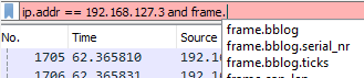
You can see that Wireshark makes suggestions to help us out. The subcomponent of frame that interests us is the interface, so start typing that to shorten the suggestion list:

The subcomponent of frame that interests us is the interface

If you recall the Wireshark-assigned interface ID from previous exercises, then you can select the interface_id subcomponent and that number. I like repeatable, memorable things, so I will use the interface_description with the name that I gave the adapter in Windows: ip.addr == 192.168.127.3 and frame.interface_description == PTL. You do not need quotes around the name:

interface_id

My display now contains traffic for that virtual machine that uses the designated physical adapter, even though none of it includes the virtual machine’s “correct” MAC address:

My display now contains traffic for that virtual machine

Expect to see many frames marked “TCP Spurious Retransmission” on the physical adapter(s) that substitute their own MAC in place of the virtual adapter’s. Network load balancing does not come free.

Expand on these Lessons

This article only scratched the surface of Wireshark’s capabilities. Most importantly, it empowers you to see below the layer 3 and higher pieces that the virtual adapters deliver into the guest operating systems. You can now see the data that enters and leaves your virtual switch and use that knowledge to find the truth behind those vague “it must be something wrong with the network” excuses.

Source :
https://www.altaro.com/hyper-v/wireshark-hyper-v-networking/

Ubiquiti UniFi Network – UniFi Cloud Adoption (Layer 3)

Updated on 5 mag 2023Print

Layer 3 adoption is the process of adopting a UniFi device to a remote UniFi Network Application. This is only recommended for advanced users, or those adopting devices to the UniFi Cloud Console. 

We highly recommend that users refer to Device Adoption for standard device adoption.

L3 Adoption Methods

For layer 3 adoption, your UniFi Network Application and connected devices must have internet access.

UniFi Network Mobile App

The Cloud Console can leverage your UniFi Network Mobile App (iOS / Android) to provide the easiest L3 adoption experience. 

  1. Refer to our UniFi Device LED Status guide to ensure the device is in a factory-default state.
  2. Connect your mobile device to the same local network as your UniFi device. 
  3. Open your UniFi Network Mobile App and connect to site you want to adopt your device.
  4. Your device should appear for adoption.

DHCP Option 43

This option leverages your DHCP server to inform your UniFi device of the location of your remote Network Application host. Those with a UniFi Gateway can easily accomplish this by entering the IP address of the remote Network Application in Option 43 Application Host Address field located in the Network Settings.

For those using a third-party gateway or DHCP server, we recommend consulting your manufacturer’s documentation to learn more.

DNS

You’ll need to configure your DNS server to resolve ‘unifi’ to your remote UniFi Network Application host.

There are two methods of specifying the Network Application host:

SSH

  1. Make sure your device is in a factory-default state. You can refer to our UniFi Device LED Status guide. 
  2. SSH into the device. You may refer to our guide on how to Login with SSH.
  3. Issue the following command: set-inform http://ip-of-host:8080/inform
  4. The UniFi device will now show up for adoption and can be treated as a standard L2 adoption.

Migrating From Another Network Application

A Layer 3 migration is useful for moving devices from a current Network application to a new Cloud Console. See Backups and Migration for more information.

Source :
https://help.ui.com/hc/en-us/articles/204909754

Ubiquiti UniFi Recovery Mode

Updated on 5 mag 2023Print

Recovery Mode is a last-resort solution to recover an unresponsive UniFi device, often resulting from power loss occurring at the same time as an update. Only use Recovery Mode if you are unable to perform a standard factory reset.

Note: UniFi Power Backup can prevent unexpected power losses from occurring.

The following UniFi devices support Recovery Mode:

  • Dream Machine, Dream Machine Pro & Dream Wall
  • Access Points (all models)
  • Cloud KeyCloud Key Gen2+
  • Cameras
  • USW Flex Mini

Before Considering Recovery Mode

If you are considering Recovery Mode, first check two key points:

  1. Reboot your UniFi device. If this resolves your symptoms, no further actions are required.
  2. Factory reset your UniFi device. If you have cloud backups, you can easily restore your settings after factory resetting. If a factory reset works, no further actions are required.

Performing a Device Recovery

Dream Machine, Dream Machine Pro & Dream Wall

  1. Download the most recent firmware for your device, found here.
  2. Completely power-off the UniFi device and unplug it from its power source.
  3. Press and hold the Reset button and then reconnect it to the power source.
  4. Continue holding the Reset button for 5 seconds, or until the display (in supported models) indicates Recovery Mode.
  5. Connect an Ethernet cable from your computer to the first LAN port (Port 1). This is usually the port nearest to the top left corner.
    • Note: Connect to the Dream Wall via Port 18, not Port 1.
  6. Configure a static IP address on your computer in the 192.168.1.0/24 range (for example, 192.168.1.11).

Windows Client

  1. Navigate to the Windows 10 Network connections
    • Settings > Network & Internet > Status > Change Adapter Option
  2. Modify the IPv4 settings of the Ethernet adapter
    • Ethernet Adapter > Properties > Internet Protocol Version 4 (TCP/IPv4) > Propertie
  3. Select the option to manually enter an IP address and add the following information:
    • IP address: 192.168.1.11
    • Subnet mask: 255.255.255.0
    • Default gateway: <blank>
    • DNS servers: <blank>

macOS Client

  1. Navigate to the mac OS Network connections.
    • System Preferences > Networks > Ethernet Adapter
  2. Select to manually enter an IP address and add the following information:
    • IP Address: 192.168.1.11
    • Subnet Mask: 255.255.255.0
    • Router: <blank>
    • DNS server: <blank>
  1. In a web browser, navigate to http://192.168.1.30 to access the Recovery Mode UI.
    • Note: The Recovery Mode UI is accessible via HTTP only (not HTTPS). Your browser may try to redirect your session to HTTPS. Use a different browser if necessary.
  2. Select Firmware Update > Choose and browse your computer for the previously downloaded firmware (.bin) image file.
  3. Wait for the upgrade process to complete and reboot the device afterwards.

Access Points

  1. Download the most recent firmware for your device, found here.
  2. Connect your AP and computer to the same network or VLAN, either through a PoE switch or by connecting the computer directly to the network (data) port on the PoE adapter.
  3. Press and hold the Reset button, and connect your computer to the available ethernet port of the AP.
  4. Continue holding the Reset button until the LED flashes white, blue, off as indicated in our LED Status Guide. This indicates your device is ready for TFTP Recovery and you can release the button.
  5. Set a static IP address on your computer to communicate with the AP, which has a default IP address of 192.168.1.20. The following is an example configuration:
    • Static IP: 192.168.1.25
      Subnet: 255.255.255.0
      Gateway: 192.168.1.20
  6. Use TFTP to move the firmware from your computer to your AP. There are various programs and methods for accomplishing this. Here are two methods for your reference.
    • Windows
      1. Use the built-in TFTP command line tool, or a separate program such as Tftpd64 or pumpKIN.
      2. Select the downloaded firmware image and transfer it to the AP.
    • macOS and Linux
      1. Open Terminal
      2. Enter TFTP mode by entering the command:tftp
      3. Once in TFTP, paste the following commands and hit enter.connect 192.168.1.20
        binary
        rexmt 1
        timeout 60
        put /path/to/firmware_name.bin
  7. The file transfer will begin. The firmware will upgrade and the device will automatically reboot once it has finished. Do not reboot it yourself.

Cloud Key

Cloud Key Gen2, Gen2 Plus

  1. Download the most recent firmware for your device, found here.
  2. Power off the system.
  3. Press and hold the Reset button and then connect it to the power source.
  4. Continue holding the Reset button for 10 seconds, until the LED flashes blue and white. The LCD screen on the front panel will also read “RECOVERY MODE.”
  5. Open your browser and type the IP address for the Cloud Key, visible on the device’s screen.
    • Note: The IP address comes from your DHCP server. If it has not been assigned an IP address, you can try the fallback: 192.168.1.30.
  6. Run the “Check Filesystem” to try searching for and repairing any problems with your storage disk that may cause system issues.
  7. Restore the firmware you downloaded in step (1). Note that this will also factory reset your device.
  8. The LED will flash white while upgrading and turn into a steady white when it is complete.
  9. If your device fails again, this is a sign that you should replace your storage disk.

Cloud Key (Gen1)

  1. Download the most recent firmware for your device, found here.
  2. Power off the system.
  3. Press and hold the Reset button and then connect it to the power source.
  4. Continue holding the Reset button for 10 seconds, until the LED flashes blue and white.
  5. Open your browser and type the IP address for the Cloud Key.
    1. Note: The IP address comes from your DHCP server. If it has not been assigned an IP address, you can try the fallback: 192.168.1.30.
    2. If your Cloud Key does have an IP address assigned by the DHCP server, the fallback IP will not work.
    3. User Tip: If you don’t know your Cloud Key’s IP address, you can use thearp -a SSH command, or software such as nmap to find the IP address.
  6. You will be taken to the Recovery Mode screen. From here you can reset, reboot, power off and most importantly upload an updated firmware bin file.
  7. Upload the firmware you downloaded in step (1).
  8. Once it is uploaded, reboot the Cloud Key to complete the firmware upgrade.
  9. The LED will flash white while upgrading and turn into a steady white when it is complete.

Cameras

  1. Unplug the PoE cable from the camera.
  2. Press and hold the Reset button, then reconnect the camera to its PoE cable.
  3. Continue holding the Reset button for at least 10 seconds, or until you see the LED flash 3 times rapidly.
  4. Release the Reset button.
  5. The device will automatically reboot to an older firmware. 
  6. To update to more recent firmware:
    1. Find your specific camera model at our Downloads page using the left hand menu.
    2. Copy the .bin file link of the firmware.
    3. Use that link to upload it via the webUI of the camera, in System Settings.
      1. Alternatively, adopt the camera to your NVR to perform an upgrade via the NVR-hosted UniFi Video user interface.

USW Flex Mini

  1. Prepare a web server (see below*).
  2. Set the server/computer’s IP to a static 192.168.1.99.
    1. The method to set a static IP on a computer varies from platform to platform. Find instructions in your product’s documentation (Windows, macOS or Ubuntu/Linux).
  3. Download the most recent firmware for your device, found here.
  4. Rename the binary to fwupdate.bin and place it in the directory that was created earlier (webserver).
  5. Power off the switch by unplugging it from its power source.
  6. Press and hold the Reset button and then connect it to the power source.
  7. Continue holding the Reset button for 10 seconds, until the LED flashes blue, white, off.
  8. The USW-Flex-Mini should be updated.

* The first step in the recovery process is to prepare a web server. See below for a walkthrough on your operating system: Windows, macOS and Ubuntu/Debian. 

Prepare a Web Server on Windows

  1. Download Python for Windows (Executable Installer) here.
  2. Open the downloaded file and make sure you select Add Python x.x to PATH during installation.
  3. After the Python installation open Command Prompt as Administrator and confirm that Python is installed correctly with the command below:
    python -V
  4. Create a directory for the web server by running the commands below:
    mkdir c:\webserver
    cd c:\webserver
  5. 5. Start the Python web server on port 80. Note that the version of Python can be found with the command from step 3:
    1. Python 3.x:
      python -m http.server 80
    2. Python 2.x:
      python -m SimpleHTTPServer 80

Prepare a Web Server on macOS

  1. Download Python for macOS here.
  2. After the Python installation open Terminal and confirm that Python is installed correctly with the command below:
    python -V
  3. Create a directory for the web server by running the commands below:
    cd ~
    mkdir webserver
    cd webserver
  4. Start the Python web server on port 80. Note that the version of Python can be found with the command from step 2:
    1. Python 3.x:
      python -m http.server 80
    2. Python 2.x:
      python -m SimpleHTTPServer 80

Prepare a Web Server on Ubuntu/Debian

  1. Install Python on your machine with the commands below:
    sudo apt-get update && sudo apt-get install python3
  2. After the Python installation open a terminal and confirm that Python is installed correctly with the command below:
    python_version=$(dpkg -l | grep “^ii” | awk ‘/python/{print$2}’ | grep “^python[0-9].[0-9]$” | head -n1)
    sudo “${python_version}” -V
  3. Create a directory for the web server by running the commands below:
    cd ~
    mkdir webserver
    cd webserver
  4. Start the Python web server on port 80. Note that the version of Python can be found with the command from step 2:
    1. Python 3.x:
      sudo “${python_version}” -m http.server 80
    2. Python 2.x:
      sudo “${python_version}” -m SimpleHTTPServer 80

Source :
https://help.ui.com/hc/en-us/articles/360043360253-UniFi-Recovery-Mode

Ubiquiti Self-Hosted UniFi Network Server as a Windows Service (Advanced)

Updated on 5 mag 2023Print

Running the UniFi Network application on Windows operating systems can be done using two methods:

  • Launcher – UniFi Network application runs in the foreground (default).
  • Windows Service – UniFi Network application runs in the background (advanced).

NOTES & REQUIREMENTS:

  • Applicable to the latest UniFi Network application versions for Windows.
  • This article applies to UniFi applications that are installed on Windows Desktop (Windows 10 / 11) and not Windows Server versions.
  • Make sure to allow the ports used by the UniFi application through the Windows Firewall. See the UniFi Network – Required Ports Reference article for more information. 

Setting up a new UniFi Network application as a service

ATTENTION:

  • The latest versions of the UniFi Network application (7.3) requires Java 11.
  • Previous versions (7.2) use Java 8.
  • Install only the x64 Java release and only one version of Java.

1. If a previous UniFi Network application is running on the system, download a backup file and then close the launcher.

2. Download the latest UniFi Network application from the Download page and run the setup.

3. You will be prompted to install Java 11. Select the following options and download the x64 .msi file for Windows:

  • Package Type: JRE
  • Version: 11

CRITICAL:

  • If the JAVA_HOME variable is not set correctly, the service installation will not be successful.
  • If you are experiencing issues with the Java 11 installer or the variable, then remove the other/older Java versions that are present on the system.

3. Run the install, and set the Set JAVA_HOME variable to Will be installed on local hard drive

java.png

CLI: Open an administrative Windows Command Prompt (CMD) window.

5. Change the directory to the location of UniFi installation.

cd "%UserProfile%\Ubiquiti UniFi\"

6. Once in the root of the UniFi folder, run the following command to install the service:

java -jar lib\ace.jar installsvc

7. Wait for the installation to complete, indicated by the Complete Installation log message.

8. Start the service with the command below: 

java -jar lib\ace.jar startsvc

9. Open a browser and navigate to the application’s IP address or https://localhost:8443.

Upgrading an existing UniFi Network application as a service

1. Download a backup file of the UniFi Network application. 

CLI: Open an administrative Windows Command Prompt (CMD) window.

2. Change the directory to the location of UniFi installation.

cd "%UserProfile%\Ubiquiti UniFi\"

3. Once in the root of the UniFi folder, issue the following to uninstall the service:

java -jar lib\ace.jar uninstallsvc

4. Wait for the service uninstall process to complete. 

5. Follow step 2 to 9 from the section above.

Source :
https://help.ui.com/hc/en-us/articles/205144550-Self-Hosted-UniFi-Network-Server-as-a-Windows-Service-Advanced-

Ubiquiti UniFi – Explaining the system.properties File

Updated on 2 mag 2023Print

Note that this article is only applicable to advanced users with the self-hosted UniFi Network Servers installed on a Windows/macOS/Linux machine. We generally recommend using a UniFi OS Host for the best experience. Visit UI.com to learn more.

This article describes what the system.properties file is used for, and how to edit it.

Introduction

The system.properties file defines system-wide parameters for the UniFi Network Server. It is found within <unifi.base> in the data folder. Some advanced use-cases include:

  • Manual override of the Application IP Interface (the address to which Devices send inform packets).
  • Advanced Database adjustments.
  • Port Assignments, for purposes of the UniFi Network application communicating with Managed Devices, redirecting Guest Portal traffic, etc.

WARNING: Before editing the file, remember to create a backup of your system. It is also necessary to stop the application before performing any change in the file to avoid errors after changes are made.

The system.properties file can be edited directly via any text editor. Keep in mind that lines preceded by hash-tags (#) exist as comments and are non-operational. Make edits at the bottom of the file. After changing this file, you’ll need to manually trigger provisioning on each site in order to make these effective.

Note: The file is created when UniFi Network runs successfully. If you cannot find the file within the <unifi_base>, create it by running UniFi Network.

Manually Specify the IP Interface for UniFi Network Application Communication

If a UniFi Host has multiple IP interfaces, the following configuration can manually set the exact IP interface that adopted APs should communicate to the Network application:

system_ip=a.b.c.d           # the IP devices should be talking to for inform

Advanced Database Configuration

Below are advanced database configurations that most users will never need. Note: We do not perform tests on these configurations, they are enabled for the convenience of database experts. One possible usage scenario is where few people run their application on a NAS, which has a smaller footprint than a normal server, hence there’s a need to reduce the required resources.

unifi.db.nojournal=false    # disable mongodb journaling
unifi.db.extraargs         # extra mongod args

The configuration below is used to facilitate UniFi Network application installation. Again, most users will never need to set this. When the is_default is set to true, the application will start with factory default configuration. For normal, everyday users, an uninstallation and then fresh re-installation is recommended over this.

is_default=true

From the UniFi Network application you can configure the auto-backup frequency, amount of backups to store, time of backup, etc. At the time of writing this, you cannot change the storage location via the application. We do have a variable in the system.properties if you wish to change the storage location. Currently, the default points to:

1. For Cloud Key: /data/autobackup (where SD card is mounted as /data by default)
2. For software installs: {data.dir}/backup/autobackup

autobackup.dir=/some/path

HSTS can be enabled, but should only be done by advanced system administrators who are familiar with it. If you run into issues, you likely will need to clear your browser’s cache after disabling this and restarting the service. To enable HSTS support add the following:

unifi.https.hsts=true
unifi.https.hsts.max_age=31536000
unifi.https.hsts.preload=false
unifi.https.hsts.subdomain=false 

NOTE: Currently no characters after the custom line(s) are allowed. This includes spaces, pound/sharp signs/comments, etc.

SMTP Related Settings

By default, SMTPS validates certificates and will reject self-signed or untrusted certificates. If your mail server uses an untrusted certificate, you must disable certificate verification with the following:

smtp.checkserveridentity=false

Starting with UniFi Network version 6.1, STARTTLS is opportunistically enabled by default; e.g. will be used if the server announces support for it, and will require a trusted certificate. If using a self-signed or untrusted certificate, you must disable STARTTLS by setting the following:

smtp.starttls_enabled=false

This only controls whether STARTTLS will be used if the server supports it. To force its use, see: starttls_required.

With UniFi Network version 6.1 and newer, STARTTLS is opportunistically enabled by default, but only required if using port 587. This behavior can be overridden by setting smtp.starttls_required=true to force the use of STARTTLS on ports other than 587, or to make STARTTLS optional on port 587, set it to false.

If smtp.starttls_enabled=false is set, the starttls_required value has no impact.

Source :
https://help.ui.com/hc/en-us/articles/205202580-UniFi-Explaining-the-system-properties-File

Ubiquiti UniFi – Tuning the Network Application for a High Number of UniFi Devices

Updated on 4 mag 2023Print

This article only applies to advanced users running UniFi on their own Windows/macOS/Linux machine, to help diagnose and optimize self-hosted UniFi Network Servers running under a high load. We generally recommend using a UniFi OS Host for the best experience. Visit UI.com to learn more.

Notes & Requirements:

  • Ensure you are running the latest version of UniFi Network, found here.
  • This article describes advanced configuration options and should only be attempted by advanced users.
  • Create a backup prior to following the instructions in this article. See UniFi – Backups and Migration for more information.

Caution must be taken when self-hosting a UniFi Network Server if there are hundreds of UniFi devices connected across multiple sites. This increased system load may lead to performance degradation if certain things are not optimized.

Symptom: High CPU Usage

One of the most important metrics to monitor is the CPU usage of the UniFi Host. High CPU usage is the first indication that there is an issue. Unfortunately there is no easy solve for this, and merely increasing the CPU is not always the answer.

Allocating Additional Memory

Before increasing the RAM allocation on your machine, first try increasing the `XMX` and `XMS` options. By default, the UniFi Network application has these set to 1GB. The following lines set the xmx and xms to values to 2GB (2048MB):

unifi.xmx=2048
unifi.xms=2048

The changes above would increase the memory that the UniFi Network application is allowed to consume from 1 to 2GB. Before moving to a machine with more CPU resources, it is recommended to max out the available memory on that machine with the above settings to see if CPU usage decreases.

If 2GB is not sufficient, administrators may want to raise the limit to 4, 8, 16, or even 32GB depending on the scale. In this case it would simply be increasing the value above in increments of 1024, i.e. 4 GB= 4096.

Note: The jstat -gcutil Java command can be used to check whether the memory allocation is sufficient on your machine. See the Oracle documentation for more information.

Increase Mongo WiredTiger Engine Cache

If you already increased the UniFi Network application memory settings to at least 4GB (xmx), you may need to also change the default Mongo WiredTiger engine cache. By default the UniFi Network Application uses:

db.mongo.wt.cache_size=256

On UniFi Network version 6.5.13 and above you can change this setting or let Mongo pick the default value by using:

db.mongo.wt.cache_size_default=true

For more information please refer to Mongo documentation.

Enabling High Performance Java Garbage Collector

If increasing memory does not solve the problem, administrators may consider also adding this line to the system.properties file:

unifi.G1GC.enabled=true

This enables a new Java Garbage Collector that can help optimize performance. However, if after these changes high CPU usage does continue after memory increase, a larger machine with more CPU cores and more memory to handle the workload may be necessary.

Changing Mongo Version/Engine

In persistent cases, administrators may consider updating MongoDB version to 3.2+ with WiredTiger as storage engine, as a means of better scaling their UniFi Network deployment. See the following links for instructions:

Symptom: Heartbeat Missed or Slow to Provision

All devices work by communicating to UniFi Network. These regular inform messages are referred to as “heartbeats”. By default, the application can handle 200 simultaneous device connections so heartbeats shouldn’t be missed unless thousands of devices are being managed. The number of simultaneous inform messages that can be processed can be set in the system.properties file by adding the following lines and adjusting the values to best suit your needs. It does not matter where these lines are added in the file.

inform.num_thread=200
inform.max_keep_alive_requests=100

The default value is 200 and the max_keep_alive_requests value should always be lower than than num_thread. Try adjusting up from there. An increase in device stability should be seen, and by pushing the configuration out to other devices, become even more stable. 

Database Connection Tuning

When running a large UniFi installation, it may be desired to run an external Mongo cluster to be able to scale the database independently from the UniFi Network application. Discussion on that can be found here on our Community Beta forum. If high CPU usage is seen on the Mongo process, it can indicate the need of a bigger box or the need to separate the mongodb process as mentioned above. Once that is done, the following can be tuned to see if it results in better application performance: 

db.mongo.connections_per_host=100
db.mongo.threads_multiplier=5

This results in 500 threads that can be waiting for a Mongo connection. So keep in mind that more threads can mean higher CPU usage because the CPU has to context-switch between threads. It may allow for higher DB throughput, but only if the Mongo process is able to consume more CPU to serve requests faster. 

Source :
https://help.ui.com/hc/en-us/articles/115005159588-UniFi-Tuning-the-Network-Application-for-a-High-Number-of-UniFi-Devices

Ubiquiti UniFi – Repairing Database Issues on the UniFi Network Application

Updated on 1 mag 2023Print

Use this article to repair the database of malfunctioning UniFi Network applications. Please note this only applies to users self-hosting the UniFi Network Server on their own Windows/macOS/Linux machine, or those hosting UniFi Network on a legacy Cloud Key.

We generally recommend using a UniFi OS Host for the best experience. Visit UI.com to learn more. 

Symptoms

  • Statistics are only recorded for a few days and then are cut off or are only intermittently available.
  • Backups including statistics data cannot be generated.
  • Settings-only backups cannot complete, or are created but are unable to be restored due to corruption.
  • An error 400 is generated when trying to open UniFi Network.
  • The UniFi Network application service will not start due to database errors.

32-bit MongoDB Limitations

32-bit MongoDB collections are limited to a total size of 2GB. While running the MMAPv1 storage engine this can cause issues when trying to shrink the aggregate collection sizes. When running a compact command on the MongoDB, the database is rewritten and defragmented without error correction. This process does not return useable disk space to the UniFi Host when the storage engine is MMAPv1.

Getting back that valuable disk space on a 32-bit MongoDB instance will require a repair of the database. This repair may be needed for those who are suspecting invalid entries, corruption, or collection scaling issues. To be able to run a database repair, the Cloud Key will have to have enough free disk space equal to the size of the current data set plus 2 gigabytes. If the dataset has already grown too large to proceed with the db.repairDatabase() command there are instructions below to work around that.

Note: The Legacy Cloud Key (UC CK) utilizes the following:

  • 32-Bit architecture
  • MMAPv1
  • MongoDB Version 2.4.10

Repairing a Cloud Key Database

  1. Establish an SSH connection with the Cloud Key.
  2. Download the mongo pruning script. As written, the script will only keep entries from the past 7 days. It will not remove entries that are required for UniFi administration. Do so by running the following command:
    cd /tmp/ wget https://help.ui.com/hc/en-us/article_attachments/360008640574/CK_repair.js
  3. Stop the UniFi service:
    service unifi stop
  4. The UniFi service will shut down the mongo process. Make sure that the UniFi service has been completely shut down. Repair the database to compact the data entries and free unused disk space field that is included in the query criteria.
    mongod –dbpath /usr/lib/unifi/data/db –smallfiles –logpath /usr/lib/unifi/logs/server.log –repair
    1. NOTE: Steps 5-8 are optional if you need to prune back the database to conserve disk space.
  5. Restart mongo using:
    mongod –dbpath /usr/lib/unifi/data/db –smallfiles –logpath /usr/lib/unifi/logs/server.log –journal –fork
    1. NOTE: Journaling may not be have been enabled in your mongo database. If so, then remove the –journal option in the above command.
  6. Execute the script to prune the stat collections that are causing the problem:
    mongo < /tmp/CK_repair.js
  7. Shut down the mongo server with this command:
    mongod –dbpath /usr/lib/unifi/data/db –smallfiles –logpath /usr/lib/unifi/logs/server.log –shutdown
    1. Note: The last command in the CK_repair.js script is “db.repairDatabase()”. It may result in an error if the stats collections have already grown too large to be repaired while the mongo server is running. If you see such an error running the script then you will need to repair the database from the command line once again by running the command in step 3.
  8. Finally, restart the UniFi service:
    service unifi start

The Cloud Key should now be able to run the Network application. If you still have database issues, please upgrade to the latest Cloud Key Gen2 Plus which does not experience this problem.

Repairing a Debian-based Linux Database

  1. Stop the UniFi service
    service unifi stop
  2. In some cases, where the journal is corrupted, it will be helpful to run the following command before repairing the database, to move it to another location:
    mv -vi /usr/lib/unifi/data/db/journal /usr/lib/unifi/data/db/journal-$(date -I)
  3. Repair the database with this command:
    mongod –dbpath /usr/lib/unifi/data/db –smallfiles –logpath /usr/lib/unifi/logs/server.log –repair
  4. Finally, restart the UniFi service:
    service unifi start
    1. Note: If this process was performed as root the file ownership may have changed. This can be changed with:
      chown -R unifi:unifi /usr/lib/unifi/data/db/
      chown -R unifi:unifi /usr/lib/unifi/logs/server.log

If you still have suspected database issues please migrate to a Cloud Key Gen2 Plus or Dream Machine Pro. These UniFi OS Hosts do not experience this type of database corruption.

Repairing a macOS Database

  1. Create a temporary working directory. For repair purposes, we will call this directory /repair. In terminal:
    mkdir ~/repair
  2. Visit the MongoDB official download website, and download the .tgz release that corresponds to your server’s CPU architecture.
    1. You can also download 2.4.14 here directly: 2.4.14.tgz
  3. Move the downloaded package to your working directory, and extract it by double-clicking it or using the application of your choice.
  4. Locate the bin/mongo binary file, and copy it to your working directory.  At this point, the downloaded .tgz package and any extra extracted files can be deleted as we only need the mongo binary.
  5. Open Terminal and move to your working directory:
    cd ~/repair
  6. Close or stop UniFi.
  7. Repair the database with this command:
    mongod –dbpath ~/Library/Application\ Support/UniFi/data/db –smallfiles –logpath ~/Library/Application\ Support/UniFi/logs/server.log –repair
  8. Open the UniFi application from Finder:
    open -n /Applications/UniFi.app

If you still have suspected database issues please migrate to a Cloud Key Gen2 Plus or Dream Machine Pro. These UniFi OS Hosts do not experience this type of database corruption.

Repairing a Windows Database

  1. Visit the MongoDB official download website, and download the .zip release that corresponds to your CPU architecture.
    1. Note: The recommended MongoDB version is 3.4.x. You can download 3.4.23 directly here: 3.4.23.zip.
  2. Extract \bin\mongod.exe to a working directory of your choice.  In this example, we will use C:\repair\ You may ignore all other files included in the .zip.
  3. Close or stop UniFi.
  4. Open the command prompt by pressing WINDOWS + R.  In the popup, type cmd, and press ENTER.
  5. Enter Working Directory:
    cd C:\repair\
  6. Repair the database with this command:
    mongod.exe –dbpath “%userprofile%\Ubiquiti UniFi\data\db” –smallfiles –logpath “%programfiles%\Ubiquiti UniFi\logs\server.log” –repair
  7. Open the UniFi application.

If you still have suspected database issues please migrate to a Cloud Key Gen2 Plus or Dream Machine Pro. These UniFi OS Hosts do not experience this type of database corruption.

How to Migrate from MMAPv1 to WiredTiger

Attention: This section does not apply to 32-bit architecture hosts including the UC-CK G1.

After UniFi Network is functional again, a user may wish to migrate it to the WiredTiger storage engine.

To verify how much space is used, run the following command:

du -shc /usr/lib/unifi/data/db/ace* /usr/lib/unifi/data/db/journal/* /usr/lib/unifi/data/db/local* | grep total

To verify which MongoDB version is being used, run the following:

mongod --version | grep "db version"

To verify what storage engine version is being used, run the following two commands:

mongo localhost:27117
db.serverStatus().storageEngine.name

How to Migrate to WiredTiger

  1. Create a backup under Settings > Maintenance > Backup with the desired retention settings.
  2. Uninstall UniFi from Windows or macOS. Purge UniFi from Debian-based Linux with the command:
    sudo dpkg -P unifi
  3. Reinstall UniFi on Windows or macOS. Reinstall UniFi on Debian-based Linux with the commands:
    cd /tmp/
    wget <https link to download>
    sudo dpkg -i unifi_sysvinit_all.deb
  4. In the UniFi Setup Wizard restore the backup from step 1.

Source :
https://help.ui.com/hc/en-us/articles/360006634094-UniFi-Repairing-Database-Issues-on-the-UniFi-Network-Application

Ubiquiti Self-Hosting a UniFi Network Server

Updated on 5 mag 2023Print

Self-hosting a UniFi Network Server should only be done by experienced network administrators. For the best and most streamlined experience, we recommend running UniFi Network on a UniFi OS Console or other UniFi OS Host, such as a Cloud Key. This will eliminate compatibility risks associated with third-party software and hardware.* Other benefits of UniFi OS Hosts include:

  • Optimized hosting and management performance
  • Automatic scheduling of backups and updates
  • Seamless email and mobile push notifications for important system activity

*UniFi also offers the Cloud Key Enterprise (on-premise) and a native Cloud Hosting subscription for scaleable deployments managing hundreds of UniFi APs.

If you choose to continue, see below for instructions to install the UniFi Network Application on your device.

Instructions

Windows

Linux

macOS

  1. Download the latest version of the UniFi Network application (UniFi-installer.exe) from the Download page.
    1. The latest versions of the UniFi Network Application (7.3) require Java 11.
    2. Previous versions (7.2) use Java 8.
    3. Install only the x64 Java release and only one version of Java.
  2. You will be prompted to install Java 11. Select the following options and download the x64 .msi file for Windows:
    1. Package Type: JRE
    2. Version: 11
  3. Install Java, and set the Set JAVA_HOME variable to Will be installed on local hard drive.
image.png
  1. After installing Java, continue the UniFi Network application installation and start it.
  2. Ensure that any anti-virus/spyware programs and the Windows firewall are not blocking the application.
  3. Open a browser, navigate to https://localhost:8443 and proceed when seeing the security warning.
  4. Proceed with the setup wizard.
  5. Adopt your first UniFi device.

Frequently Asked Questions

1. Does the UniFi Network application have to run at all times?

If the UniFi Network application is turned off, adopted UniFi devices (access points, switches) will keep functioning. 

However, it is highly recommended to keep the UniFi Network application running at at all times. This enables you gather accurate statistics and make configuration changes whenever needed. 

If you are not able to keep the Self-Hosting Network Server running continuously, then we recommend to upgrade to a UniFi OS Console, which is optimized to run UniFi Network and other applications.

2. Can I manage UniFi Devices that are adopted by another UniFi Network application?

No. The UniFi Network application installed on Windows/macOS/Linux is not a viewer for other UniFi Network applications (running on UniFi OS Consoles or other hosts).

3. The UniFi Network application is running slow.

Verify if the Self-Hosted Network Server is capable of running the UniFi Network application. The more UniFi and client devices that are connected, the more resources that will be needed.

Please be aware that self-hosting the UniFi Network application is an advanced setup for those familiar with network administration. If you are experiencing poor performance, we recommend upgrading to a UniFi OS Console, which is optimized to run UniFi Network and other applications.

4. The UniFi Network application is not able to start.

Verify if the Self-Hosted Network Server is capable of running the UniFi Network application and that the correct version of Java is installed. 

If you continue to experience issues, try installing the application on a different host machine.

Please be aware that self-hosting the UniFi Network application is an advanced setup for those familiar with network administration. If you are unable to get the UniFi Network application running on your host machine, we recommend upgrading to a UniFi OS Console, which is optimized to run UniFi Network and other applications. 

5. The UniFi Network application starts up, but I do not see any nearby UniFi devices.

Make sure that the firewall on the host machine is allowing the ports needed by UniFi and that the UniFi Network application is not blocked by any anti-virus/spyware programs.

Also make sure that the UniFi devices and the application are on the same network. If not, then remote adoption is required.

6. I get a “Your connection is not private” warning when accessing via my browser.

This can be safely ignored. Proceed to the next page.

7. What are the UniFi Network application system requirements?

At a bare minimum, we recommend the following system requirements (make sure to read the Release Notes for more details about a particular version):

  • Operating system:
    • Linux: Ubuntu Desktop / Server 22.04; Debian 11 “Bullseye”
    • Windows: Windows 10; Windows Server 2016
    • macOS: Mavericks 10.9, 10.10 Yosemite, 10.11 El Capitan, 10.12 Sierra, 10.13 High Sierra, 10.14 Mojave, 10.15 Catalina.
  • CPU: x86-64 Processor (Intel / AMD x64 Processors)
  • RAM: 2GB
  • Network: 100Mbps Wired Ethernet
  • HDD: Minimum 10GB free (20GB or more preferred)
  • Java: Java Runtime Environment (JRE) 11
  • Web Browser: Google Chrome
  • MongoDB: version 3.2 or later. Mongo is offered bundled: default is 2.4.14 (for macOS and Windows only).

Note: You will need to continually increase your system specs as you begin to adopt and manage more devices.

Source :
https://help.ui.com/hc/en-us/articles/360012282453-Self-Hosting-a-UniFi-Network-Server

Ubiquiti UniFi – Advanced Updating Techniques

Updated on 5 mag 2023Print

Use advanced techniques as a last resort to update UniFi devices and UniFi software when it is not possible to do so via the user interface. 

We highly recommend that most users enable automatic updates, or trigger updates through the user interface. See How to Update UniFi to learn more.

Update UniFi Devices via Web Application

Updating via the Device Property Panel

Use Case: You want to try Early Access firmware releases for specific devices, or you want to return to an official release after trying an EA release.

1. Copy the firmware release link from a post on community.ui.com/releases.

image1.png

2. Paste the link in the address bar found in the Settings tab of the device’s properties panel.

image2.png

Updating via Your Network Cache

Use Case: You prefer to download and store updates in your Network application so they can be used by other devices, as opposed to downloading multiple, device-specific files from the internet. This is an ideal solution for reducing bandwidth within high-volume networks that host a large number of similar UniFi devices. It is also suitable for the advanced users who disable internet access on their UniFi device’s management network.

Device updates can be cached in your Network application’s System Settings. Once an update is cached, you can open to your UniFi Devices page and click Update Available.

Note: The Cache link will appear when you hover your cursor over an update.image3.png

Updating via SSH

Please note that SSH updating is not an officially supported process and may prevent your UniFi OS console from functioning. Only do this at the request of UI Support. It is only prescribed to work around specific scenarios, such as when:

  • Prior, traditional, update attempts have failed, likely due to an incorrect network configuration. For more details, see How to Update UniFi.
  • Your UniFi Network device is not being discovered or cannot be adopted because it has been preloaded with outdated firmware.
  • Your UniFI OS Console cannot be set up because it has been preloaded with an outdated version of UniFi OS.

UAP/USW (Internet) 

  1. Copy the update link from community.ui.com/releases.
  2. SSH into your device.
  3. Run the following command:upgrade paste_download_link_here Example:upgrade https://dl.ui.com/unifi/firmware/UAL6/5.60.1.12923/BZ.mt7621_5.60.1+12923.210416.1641.bin

UAP/USW (No Internet) 

  1. Download the desired firmware update from community.ui.com/releases.
  2. Use the following SCP command to copy the file into the /tmp folder of your device from your workstation. This requires a compatible SCP application (e.g., Terminal on macOS and Linux, PuTTY/PowerShell on Windows).scp /folder_path/firmwarefile.bin <user>@<IP of device>:/tmp/fwupdate.binExample:
    scp /Users/alexpro/Desktop/BZ.mt7621_5.60.1+12923.210416.1641.bin Alex@192.168.1.219:/tmp/fwupdate.bin 
  3. Enter your SSH password when prompted.
  4. SSH into your device.
  5. Run the following command:syswrapper.sh upgrade2 &

UDM, UDM Pro, UDM SE, UDR, UDW, UCK G2, UCK G2 Plus, UNVR, UNVR Pro, UXG Pro (Internet)

  1. Copy the update link from community.ui.com/releases.
  2. SSH into your device.
  3. Run the following command:
ubnt-systool fwupdate paste_download_link_here 

Example:

ubnt-systool fwupdate https://fw-download.ubnt.com/data/unifi-dream/dd49-UDR-2.4.10-cd3afa000ebf4a4fb15374481539961c.bin

If your UDM, UDM Pro or UXG-Pro runs version 1.x, then please use the ubnt-upgrade command.

Example:

ubnt-upgrade https://fw-download.ubnt.com/data/udm/1adc-udmpro-1.12.38-ca8a490ac2b04247abb3f7d3e3eae01a.bin

UDM, UDM Pro, UDM SE, UDR, UDW, UCK G2, UCK G2 Plus, UNVR, UNVR Pro, UXG Pro (No Internet)

  1. Download the desired firmware update from community.ui.com/releases.
  2. Use the following SCP command to copy the file into the /tmp (/mnt/data for version 1.12 and below) folder of your device from your workstation. This requires a compatible SCP application (e.g., Terminal on macOS and Linux, PuTTY/PowerShell on Windows).scp /folder_path/firmwarefile.bin <user>@<IP of device>:/tmp/fwupdate.binExample:
    scp /Users/alexpro/Desktop/UDR-2.4.10.bin root@192.168.1.1:/tmp/fwupdate.binIf you are running Version 1.12 and below, use the following command:
    scp /folder_path/firmwarefile.bin <user>@<IP of device>:/mnt/data/fwupdate.binExample:
    scp /Users/alexpro/Desktop/UDR-2.4.10.bin root@192.168.1.1:/mnt/data/fwupdate.bin
  3. Enter your SSH password when prompted.
  4. SSH into your device.
  5. Run the following command:ubnt-systool fwupdate /tmp/fwupdate.binVersion 1.12 and below:
    ubnt-upgrade /mnt/data/fwupdate.bin

USG (Internet) 

  1. Copy the update link from community.ui.com/releases.
  2. SSH into your device.
  3. Run the following command:upgrade <paste_download_link_here> Example:
    upgrade https://dl.ui.com/unifi/firmware/UGW3/4.4.56.5449062/UGW3.v4.4.56.5449062.tar

USG (No Internet) 

  1. Download the desired firmware update from community.ui.com/releases.
  2. Rename the file: upgrade.tar
  3. Use the following SCP command to copy the file into the /home/<user> folder of your USG from your workstation. This requires a compatible SCP application (e.g., Terminal on macOS and Linux, PuTTY/PowerShell on Windows).scp /folder_path/upgrade.tar <user>@<IP of device>:/home/<user>/upgrade.tarExample:
    scp /Users/alexpro/Desktop/upgrade.tar Alex@192.168.1.1:/home/Alex/upgrade.tar
  4. Enter your SSH password when prompted.
  5. SSH into your device.
  6. Run the following command:sudo syswrapper.sh upgrade upgrade.tar

Manually Update the Network Application

  1. Download the desired application update from community.ui.com/releases.
  2. SSH into your device.
  3. Run the following command (UDM/UDM Pro if still running UniFi OS 1.x):unifi-os shell
  4. Remove previously installed files:rm /tmp/unifi_sysvinit_all.deb &> /dev/null
  5. Store the new application version on your device using the download link:curl -o “/tmp/unifi_sysvinit_all.deb” <network application link.deb>Example:
    curl -o “/tmp/unifi_sysvinit_all.deb” https://dl.ui.com/unifi/6.2.26-a79cb15f05/unifi_sysvinit_all.deb
  6. Once downloaded, install the new version:apt-get install -y /tmp/unifi_sysvinit_all.deb
  7. Following installation, remove the downloaded file:rm /tmp/unifi_sysvinit_all.deb

Updating Devices in a Broken State

In rare occurrences, a device may stop functioning. UniFi APs may be updated using our TFTP Recovery. This should only be used if your AP completely stops functioning as a last resort prior to submitting an RMA. UniFi OS Consoles and gateways my be updated using Recovery Mode. This should only be used if prompted on your device’s LCM screen.

Source :
https://help.ui.com/hc/en-us/articles/204910064-UniFi-Advanced-Updating-Techniques

Ubiquiti UniFi – Backups and Migration

Types of Backups

There are UniFi OS backups and also application-specific backups. We strongly recommend using a UniFi OS backup for UniFi OS Hosts (i.e., Dream products, Cloud Key Gen2 Plus, and Network Video Recorders) because they capture backups for UniFi applications as well.

UniFi OS Backups

UniFi OS backups contain your entire system configuration, including settings for your UniFi OS Console, users, and applications. If Remote Access is enabled, UniFi OS Cloud backups are created weekly by default. You can also create additional Cloud backups or download localized backups at any time. 

UniFi OS backups are useful when:

  • Restoring a prior system configuration after making network changes.
  • Migrating all applications to a new UniFi OS Console that is the same model as the original.

Note: Backups do not include data stored on an HDD, such as recorded Protect camera footage.

Application Backups

Each UniFi application allows you to back up and export its configuration. Application backups contain settings and device configurations specific to the that application.

Application backups are useful when:

  • You want to restore a prior application configuration without affecting your other applications.
  • You want to migrate a Self-Hosted Network Server application to a UniFi OS Console.
  • You want to migrate your devices between two different UniFi OS Console models.
  • You need to back up a self-hosted Network application.

Note: Backups do not include data stored on an HDD, such as recorded Protect camera footage.

UniFi OS Console Migration

UniFi OS backups also allow you to restore your system configuration should you ever need to replace your console with one of the same model.

To do so:

  1. Create a Cloud backup or download a local backup. This can be done in your UniFi OS Settings.
  2. Replace your old UniFi OS Console with the new one. All other network connections should remain unchanged.
  3. Restore your system configuration on the new UniFi OS Console using the backup file. This can be done either during the initial setup or afterwards in your UniFi OS settings.

Note: Currently, UniFi OS backups cannot be used to perform cross-console migrations, but this capability will be added in a future update.

If you are migrating between two different console models, you will need to restore each application’s configuration with their individual backups. These file application backups will not include UniFi OS users or settings. 

See below for more information on using the configuration backups during migrations.

Migrating UniFi Network

Before migrating, we recommend reviewing your Device Authentication Credentials found in your Network application’s System Settings. These can be used to recover adopted device(s) if the migration is unsuccessful. 

Standard Migration

This is used when all devices are on the same Layer 2 network (i.e., all devices are on the same network/VLAN as the management application’s host device). 

Note: If you are a home user managing devices in a single location and have not used the set-inform command or other advanced Layer 3 adoption methods, this is most likely the method for you.

  1. Download the desired backup file (*.unf) from your original Network application’s System Settings
  2. Ensure that your new Network application is up to date. Backups cannot be used to restore older application versions.
  3. Replace your old UniFi OS Console with the new one. All other network connections should remain unchanged.
  4. Restore the backup file in the Network application’s System Settings.
  5. Ensure that all devices appear as online in the new application. If they do not, you can try Layer 3 adoption, or factory-reset and readopt your device(s) to the new Network application.

If a device appears as Managed by Other, click on it to open its properties panel, then use its Device Authentication Credentials (from the original Network application’s host device) to perform an Advanced Adoption.

Migrating Applications That Manage Layer 3 Devices

This method is for users that have performed Layer 3 device adoption (e.g., devices are on a different network/VLAN than the application’s host device). This may also be useful when migrating to a Network application host that is not also a gateway.

  1. Download the desired backup file (*.unf) from your original Network application’s System Settings
  2. Enable the Override Inform Host field on the original Network application’s host device, then enter the IP address of the new host device. This will tell your devices where they should establish a connection in order to be managed. Once entered, all devices in the old application should appear as Managed by Other.
    • When migrating to a Cloud Console, you can copy the Inform URL from the Cloud Console’s dashboard. You will need to remove the initial http:// and the ending :8080/inform
  3. Ensure that your new Network application is up to date. Backups cannot be used to restore older application versions.
  4. Restore the backup file in the Network application’s System Settings.
  5. Ensure that all devices appear as online in the new application. If they do not, you can try Layer 3 adoption, or factory reset and readopt your device(s) to the new application.

If a device appears as Managed by Other, click on it to open its properties panel, then use its Device Authentication Credentials (from the original Network application’s host) to perform an Advanced Adoption.

Exporting Individual Sites from a Multi-Site Host

Certain Network application hosts (e.g., Cloud Key, Cloud Console, self-hosted Network Server) can manage multiple sites. Site exportation allows you to migrate specific sites from one multi-site host to another. To do so:

  1. Click Export Site in your Network application’s System Settings to begin the guided walkthrough.
  2. Select the device(s) you wish to migrate to your new Network application.
  3. Enter the Inform URL of your new host. This will tell your devices where they should establish a connection in order to be managed. Once entered, all devices in the old application should appear as Managed by Other in the new one.
    • When migrating to a Cloud Console, you can copy the Inform URL from the Cloud Console’s dashboard. You will need to remove the initial http:// and the ending :8080/inform.
  4. Go to your new Network application and select Import Site from the site switcher located in the upper-left corner of your dashboard.
    • Note: You may need to enable Multi-Site Management in your System Settings.
  5. Ensure that all devices appear as online in the new application. If they do not, you try Layer 3 adoption, or factory reset and readopt your device(s) to the new application.

If a device appears as Managed by Other, click on it to open its properties panel, then use its Device Authentication Credentials (from the original Network application’s host) to perform an Advanced Adoption.

Migrating UniFi Protect

We recommend saving your footage with the Export Clips function before migrating. Although we provide HDD migration instructions, it is not an officially supported procedure due to nuances in the RAID array architecture. 

Standard Migration

  1. Download the desired backup file (*.zip) from the original Protect application’s settings. 
  2. Ensure that your new Protect application is up to date. Backups cannot be used to restore older application firmware.
  3. Replace your old UniFi OS Console with the new one. All other camera connections should remain unchanged.
  4. Restore the backup file in the Protect application’s settings.

HDD Migration

Full HDD migration is not officially supported; however, some users have been able to perform successful migrations by ensuring consistent ordering when ejecting and reinstalling drives into their new console to preserve RAID arrays.

Note: This is only possible if both UniFi OS Consoles are the same model.

  1. Remove the HDDs from the old console. Record which bay each one was installed in, but do not install them in the new console yet.
  2. Turn on the new console and complete the initial setup wizard. Do not restore a Protect application or Cloud backup during initial setup.
  3. Upgrade the new console and its Protect application to a version that is either the same or newer than the original console.
  4. Shut down the new console, and then install the HDDs in the same bays as the original console.
  5. Turn on the new console again. The Protect application should start with its current configuration intact, and all exported footage should be accessible.


Source :
https://help.ui.com/hc/en-us/articles/360008976393

Exit mobile version