Use this article to compare the different antenna radiation patterns of our UniFi Access Points. For an explanation on how to read antenna radiation patterns see UniFi – Introduction to Antenna Radiation Patterns.
- About Radiation Patterns
- Radiation Plot Format
- Comparison Table
- Model Summary Plots
- Antenna Files (.ant)
- Related Articles
About Radiation Patterns
Radiation patterns can be used to better understand how each Ubiquiti UniFi access point model broadcasts wireless signal. These patterns are what antenna engineers call reciprocal—in that the transmit-power (the capability of the AP to ‘speak’) will be highest at the peaks, and so will the receive-sensitivity (the capability of the AP to ‘hear’).
Please note that these radiation patterns are gathered in a fully anechoic environment. Their shape, peak gain/directivity and efficiency will change in installed environments. Every deployment will behave differently due to interference, materials, geometries of structures, and how these materials behave at 2.4GHz and 5GHz.
With that in mind, use these radiation plots as a “general guide” to identify where most of the energy (and receive sensitivity) of the UniFi APs is being directed; but keep present that the ultimate way to know how successful the coverage design is—is to measure it. Measure signal strength and coverage before (with mock positioning), during (as you install), and after to guarantee that you have the coverage you want—and don’t have the coverage you don’t want (for example with self-interference: APs hearing each other or other AP stations on the same channel).
Radiation Plot Format
Radius represents ‘elevation’, with 0° representing antenna gain straight under the AP, and 90° representing antenna gain at horizon. The degrees on the circumference represent ‘Azimuth’. That is to say, left/right/front/back of the AP, when mounted overhead.
Comparison Table
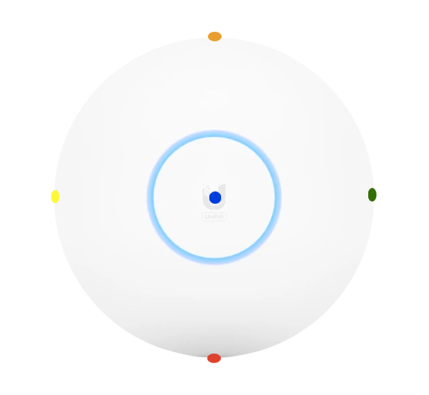
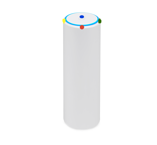
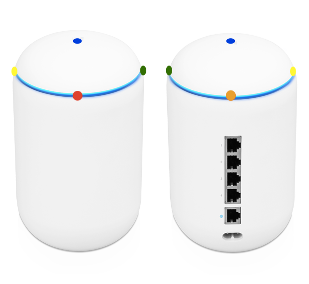
Use this table to compare the radiation patterns of each UAP. The first column shows where the respective colored dots found in each radiation plot is placed in the actual devices. Note that colored dots in the plots might be in the outer perimeter or closer to center.
Note: Varying scales are represented in the graphs below. Consider each graph individually and take note of scale when comparing products.
| Directional color dots on device | 5GHz LowFrequency | 5GHz MidFrequency | 5GHz HighFrequency | 2.4GHzFrequency |
 U6-Lite U6-Lite | 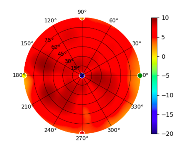 | 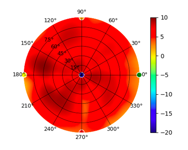 | 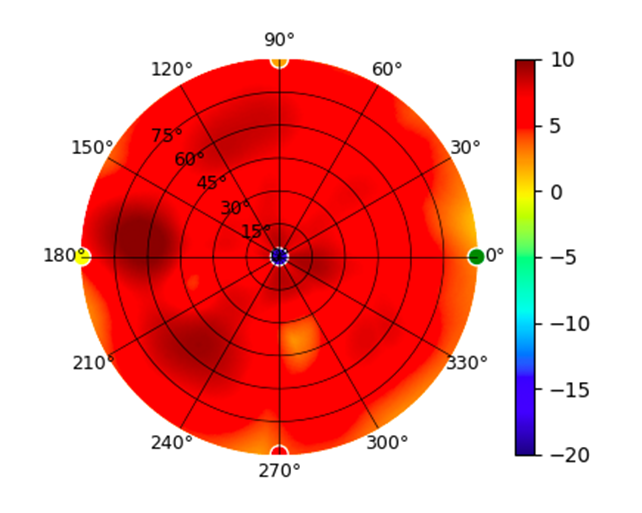 | 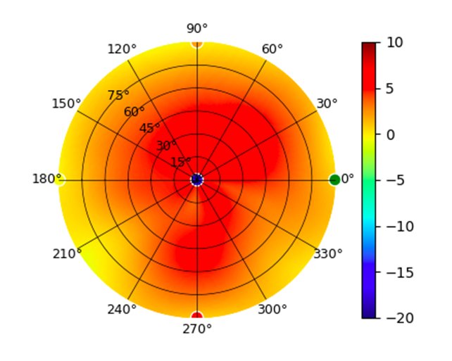 |
| U6-Pro | 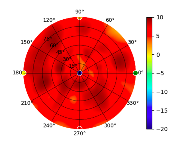 | 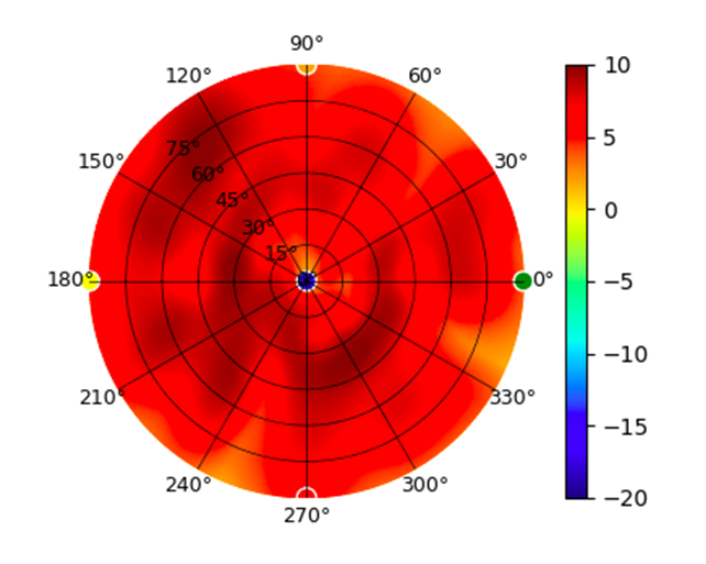 | 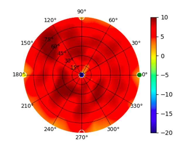 | 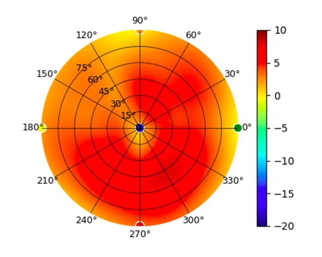 |
| U6-LR | 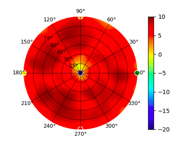 (5.20GHz) (5.20GHz) | 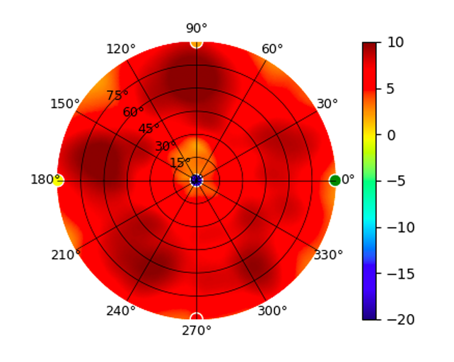 | 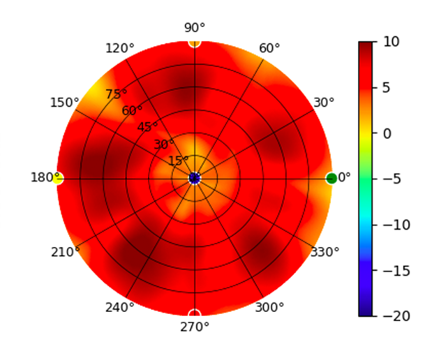 (5.80GHz) (5.80GHz) | 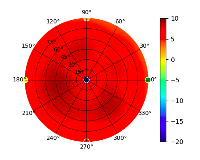 |
 U6-Mesh U6-Mesh | 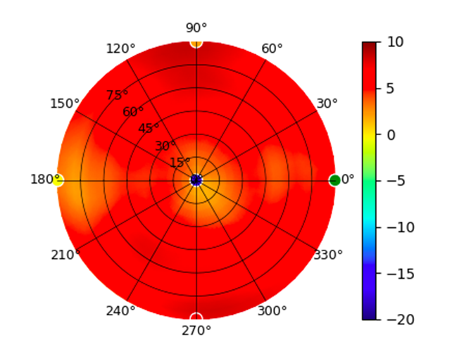 (5.20GHz) (5.20GHz) | 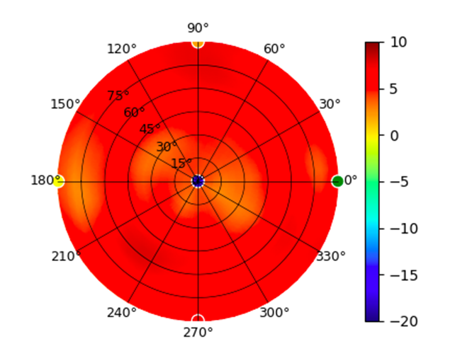 | 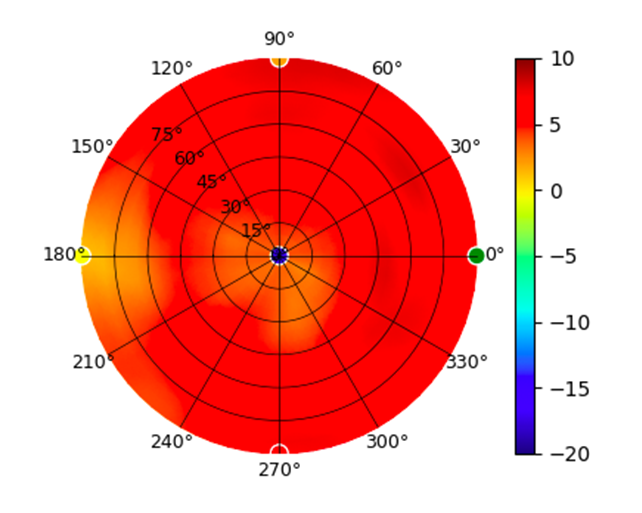 (5.80GHz) (5.80GHz) | 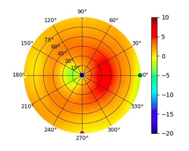 |
 UDM UDM | 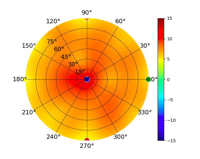 | 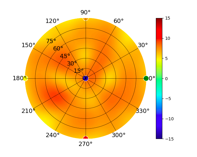 | 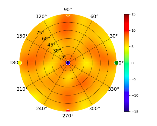 | 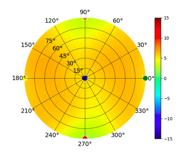 |
| UWB-XG |  (High Gain) (High Gain) |  (High Gain) (High Gain) |  (High Gain) (High Gain) | The UWB-XG models do not operate on the 2.4GHz band. |
 UAP-FlexHD UAP-FlexHD | 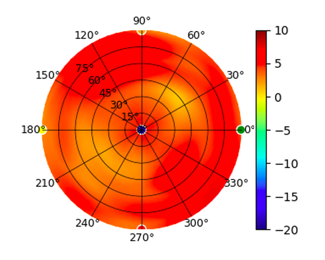 | 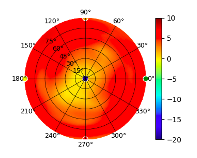 |  |  |
| UAP-IW-HD |  | 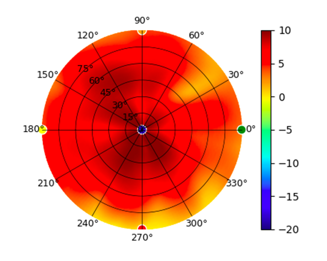 | 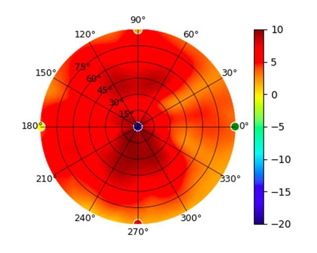 | 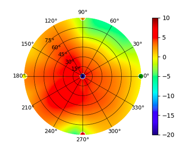 |
| UAP-nanoHD | 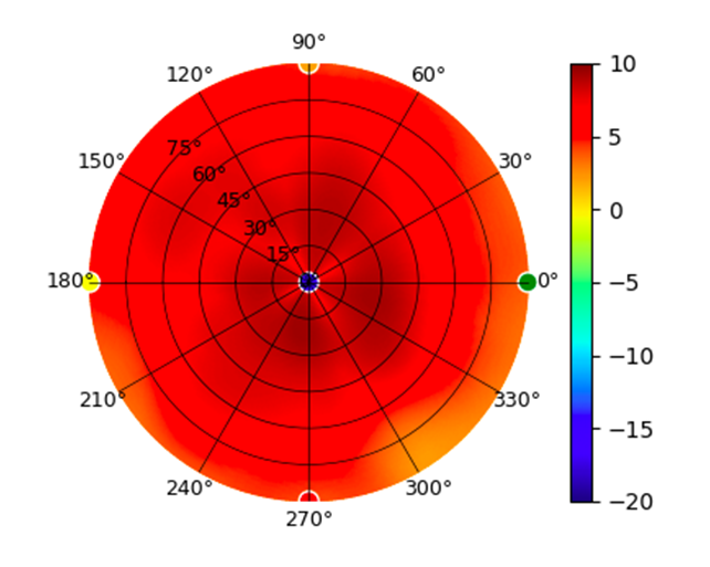 | 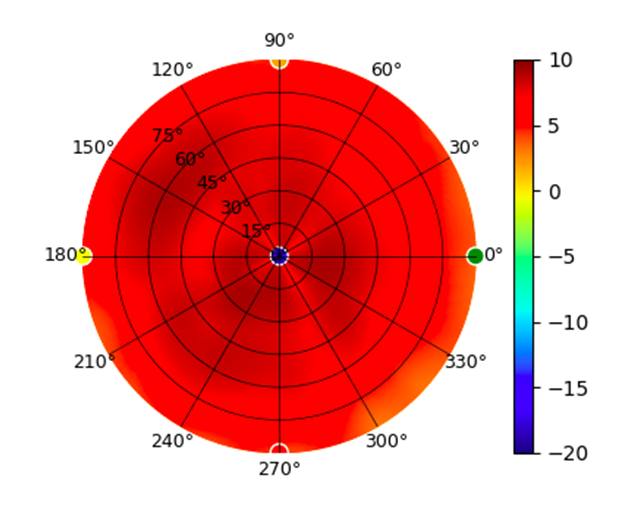 |  |  |
| UAP-HD |  | 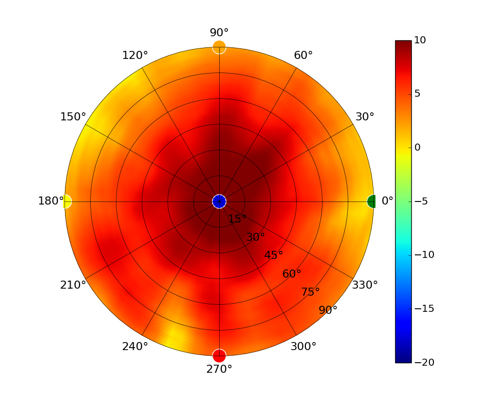 | 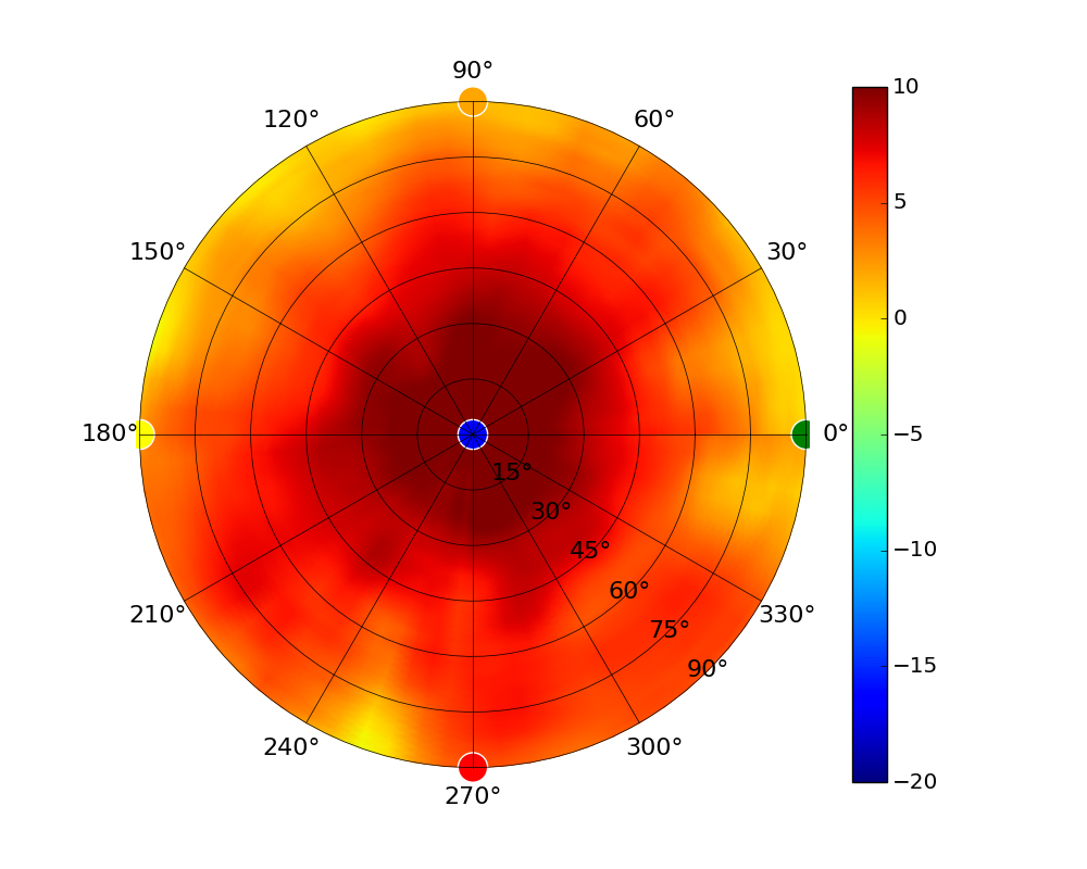 | 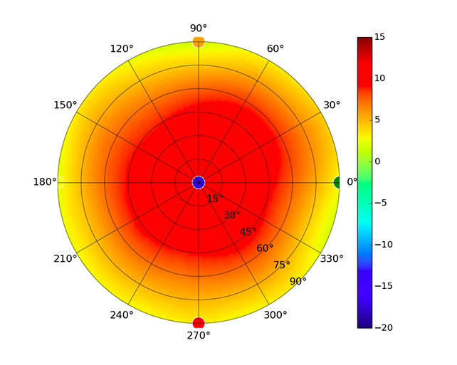 |
| UAP-XG |  |  |  | 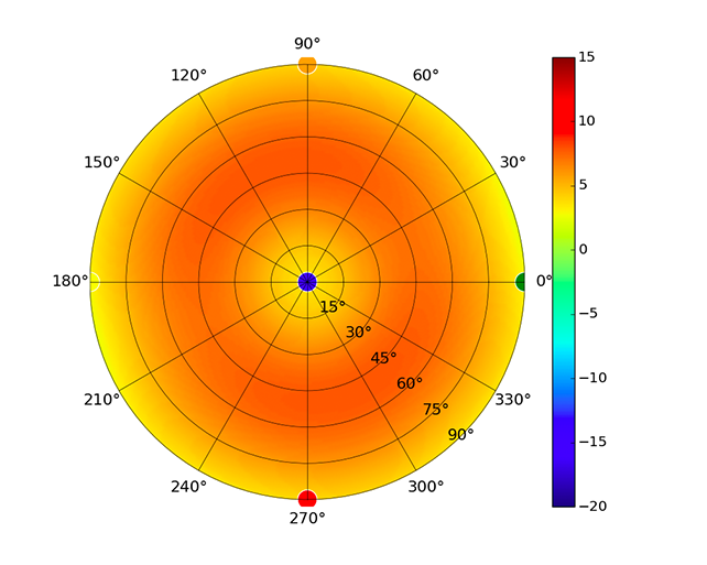 |
| UAP-SHD | 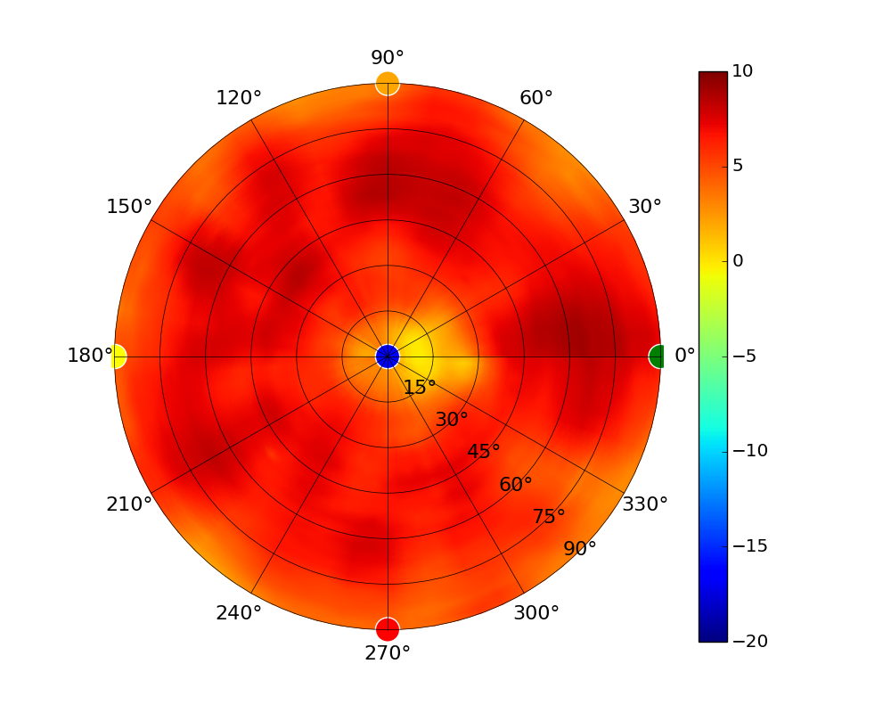 | 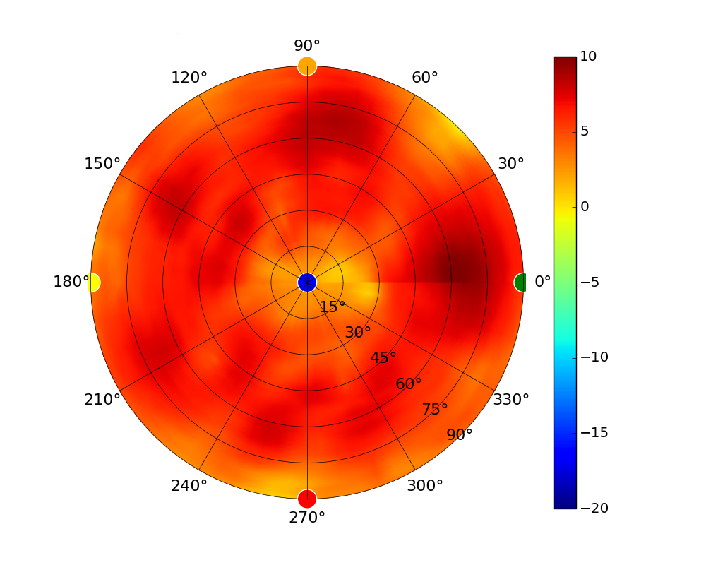 | 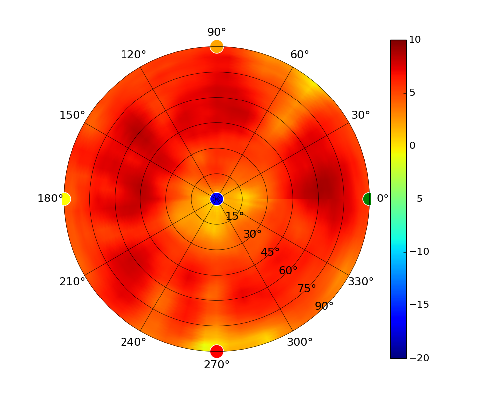 | 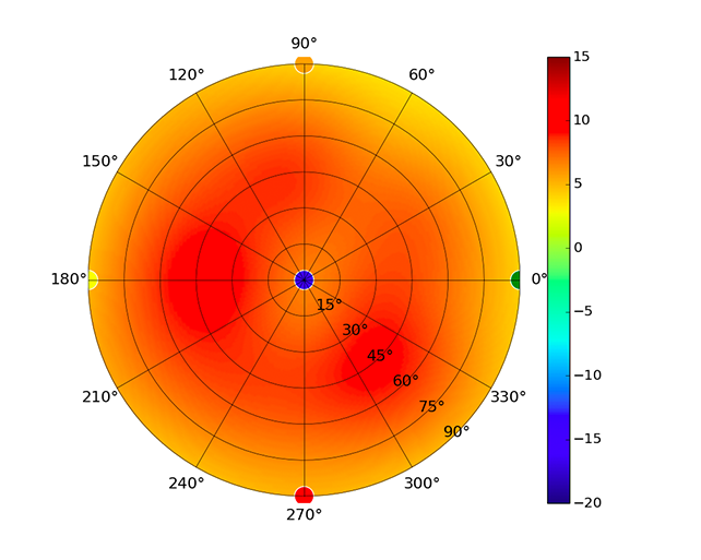 |
| UAP-AC-LR | 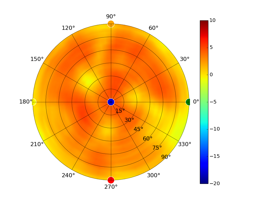 | 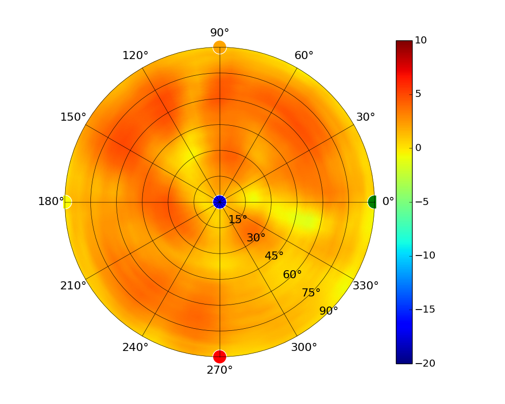 | 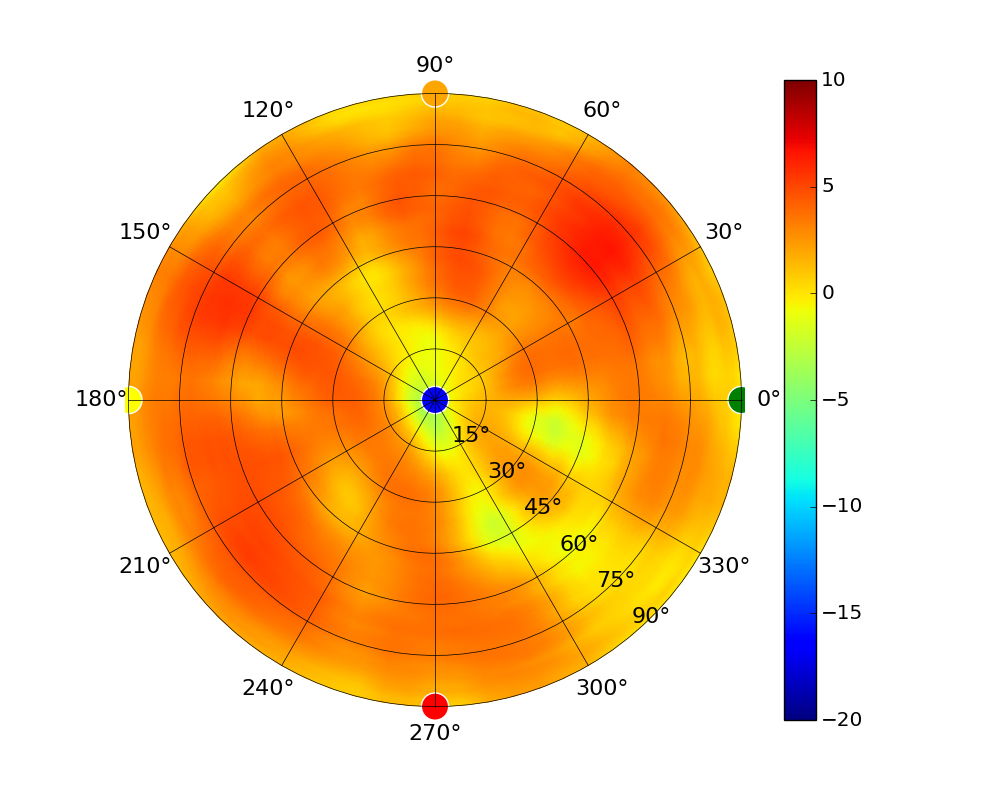 | 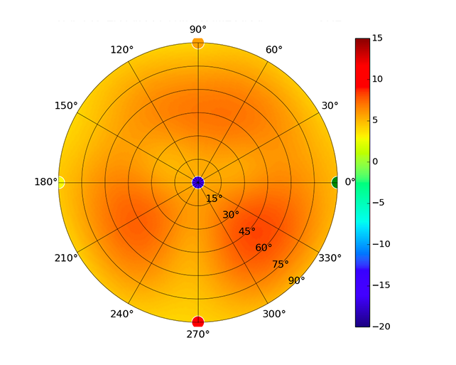 |
| UAP-AC-M-PRO | 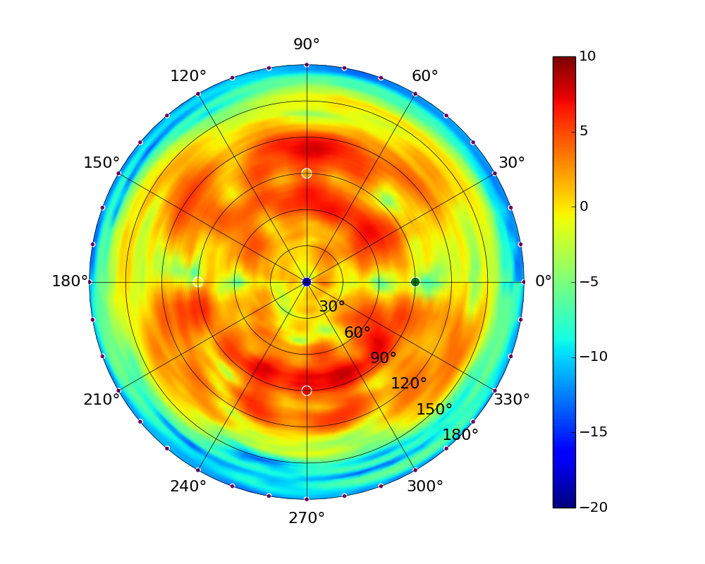 | 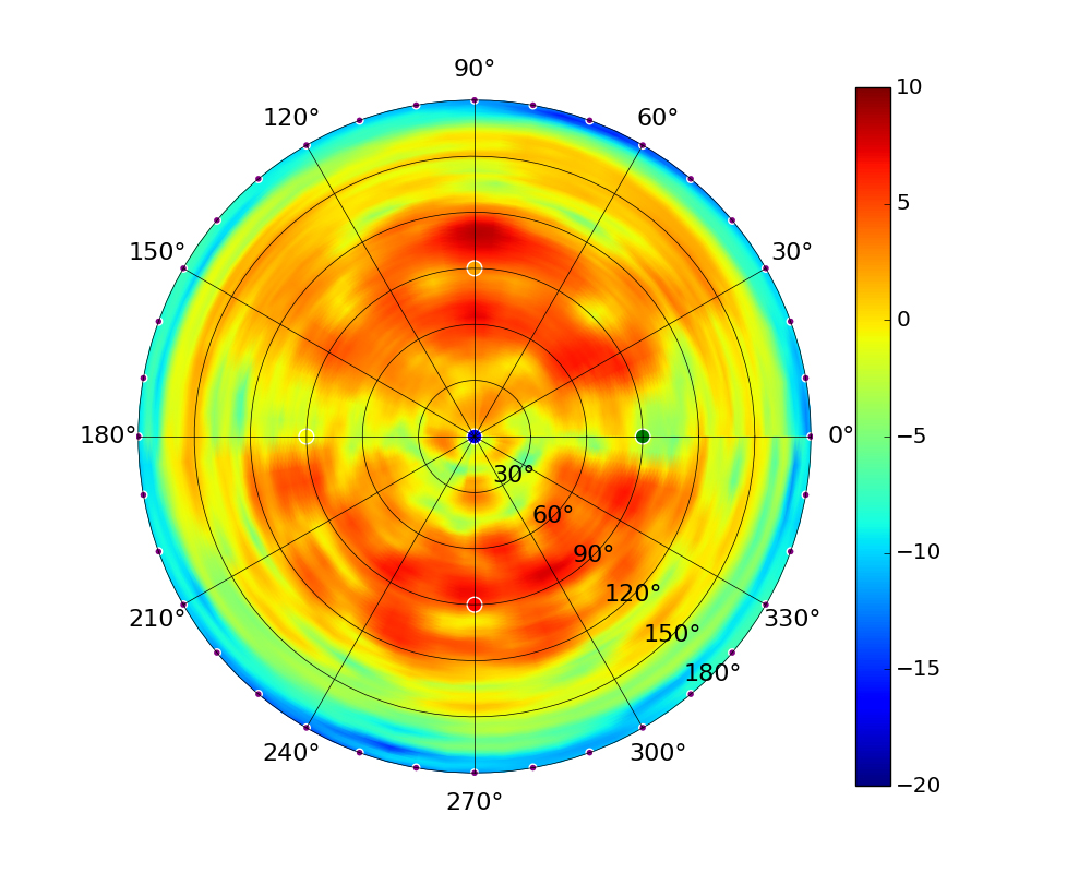 | 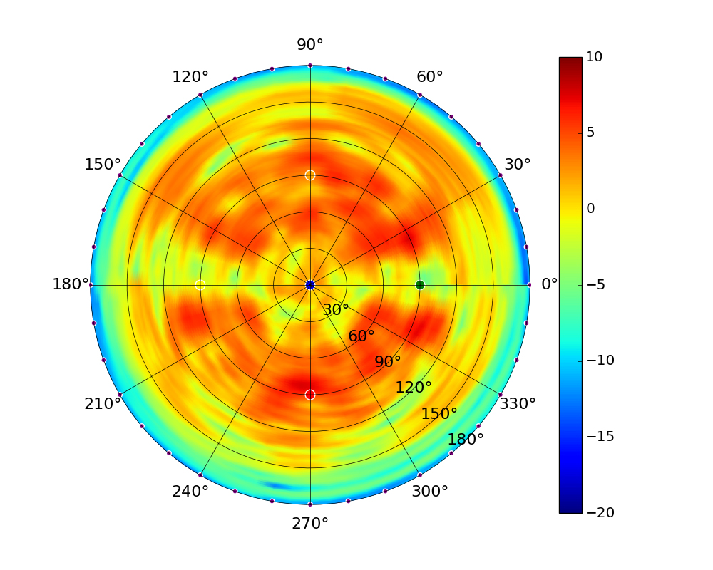 | 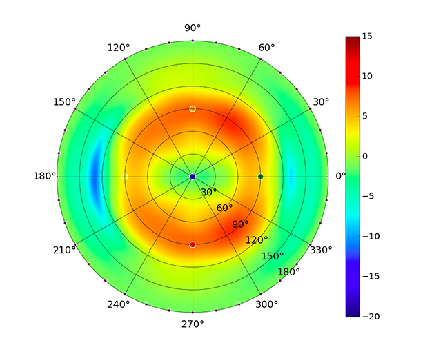 |
| UAP-AC-M | 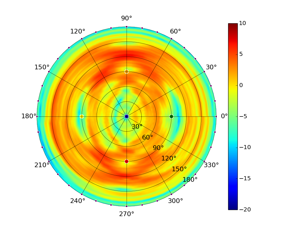 | 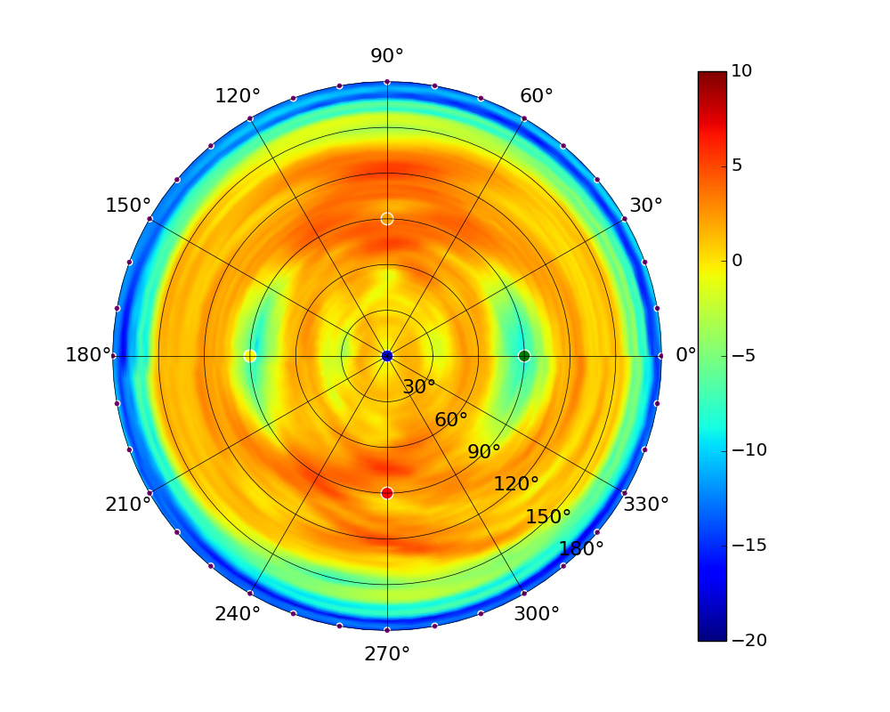 | 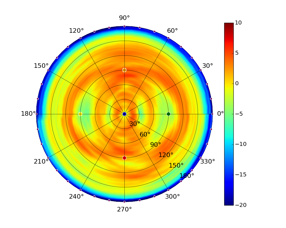 | 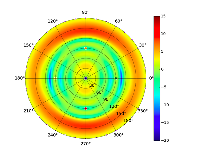 |
| UAP-AC-IW | 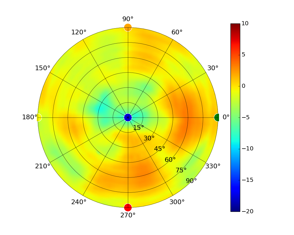 |  |  |  |
| UAP-AC-Lite | 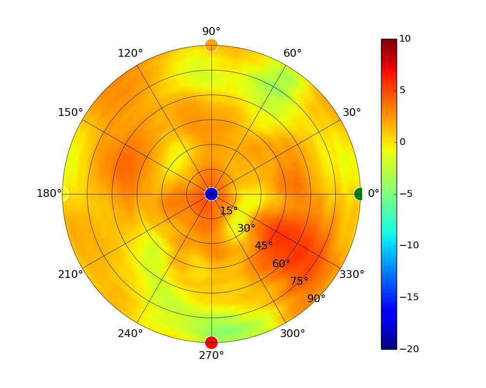 | 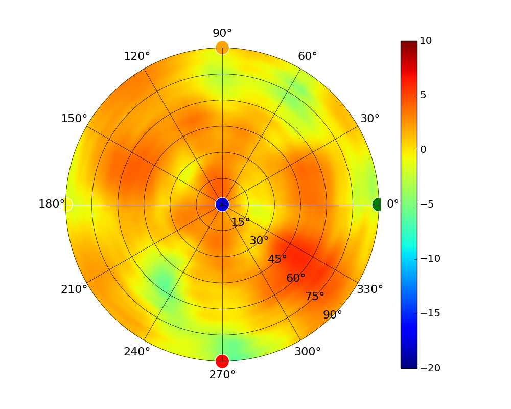 | 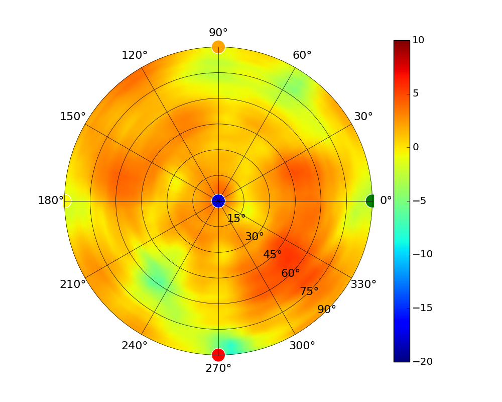 | 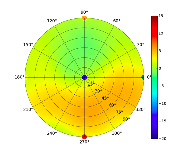 |
| UAP-AC-PRO | 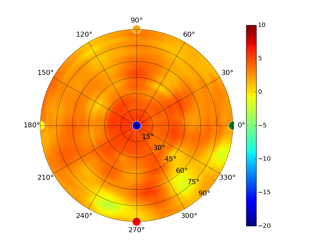 | 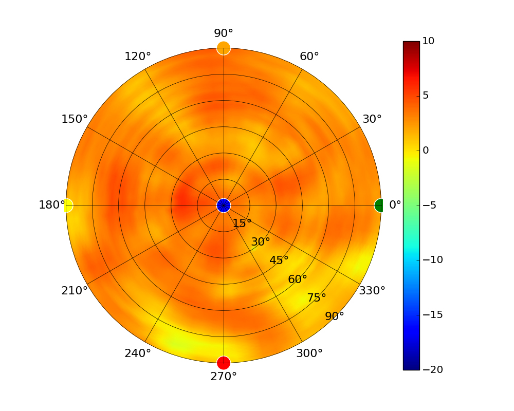 | 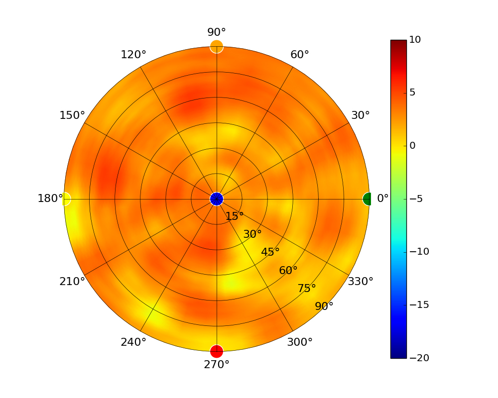 | 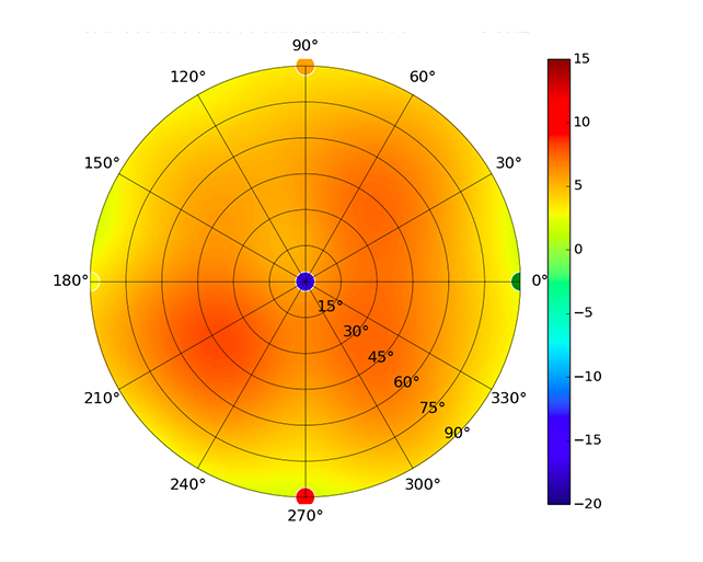 |
| UAP-AC-IW-PRO | 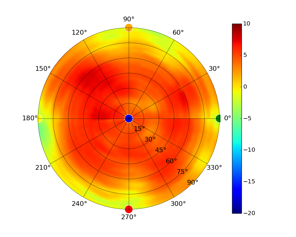 | 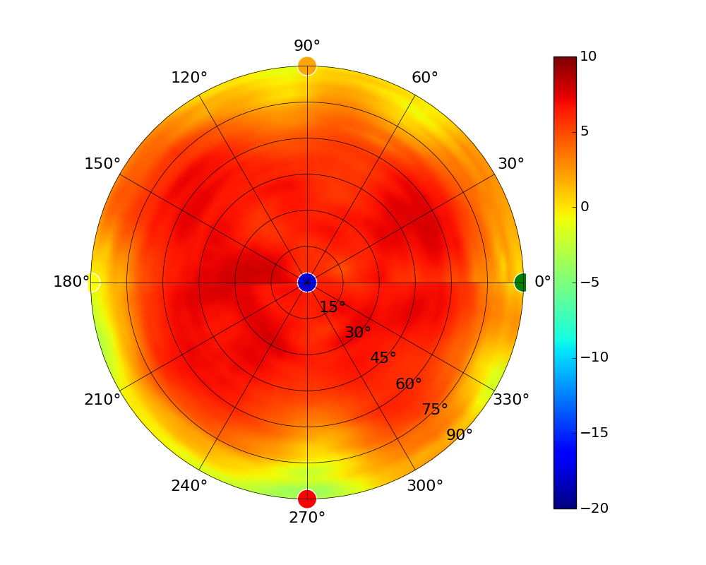 | 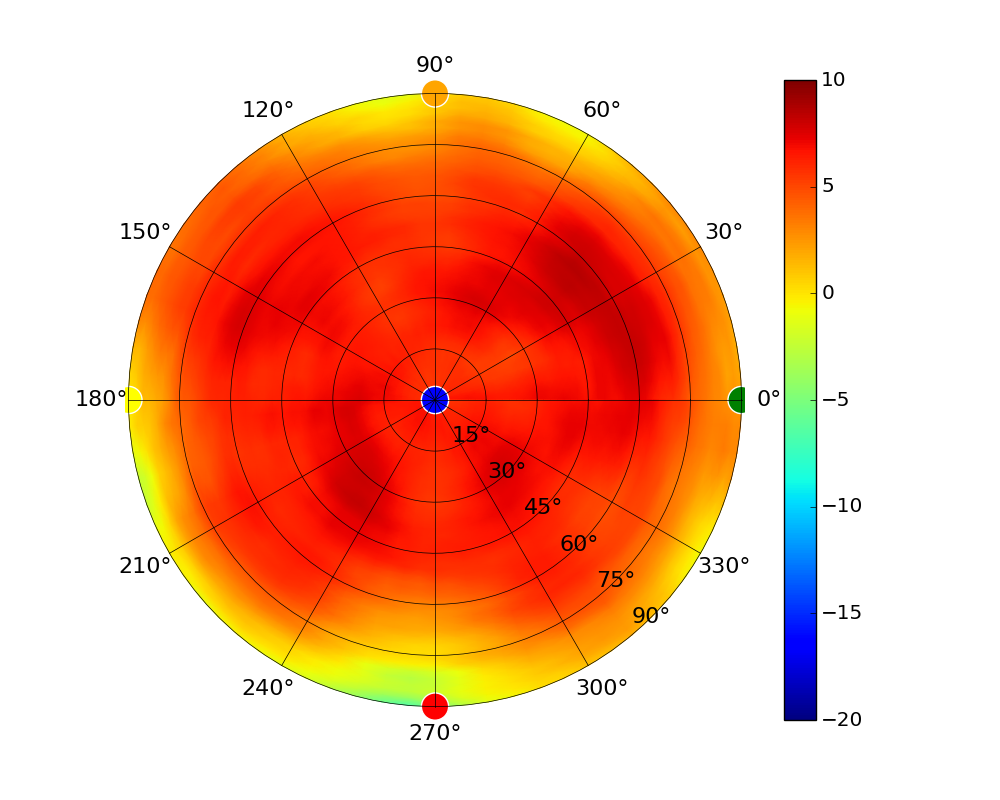 | 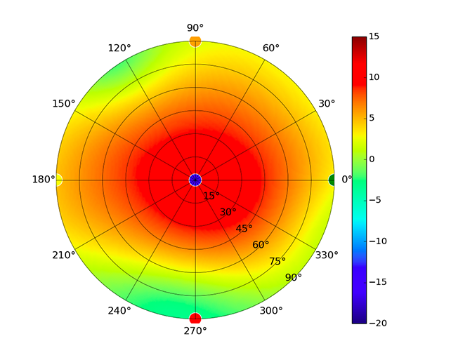 |
| UMA-D |  |  |  | 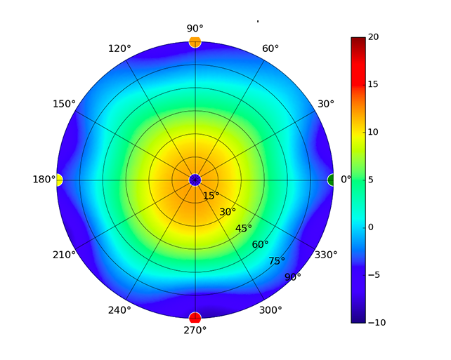 |
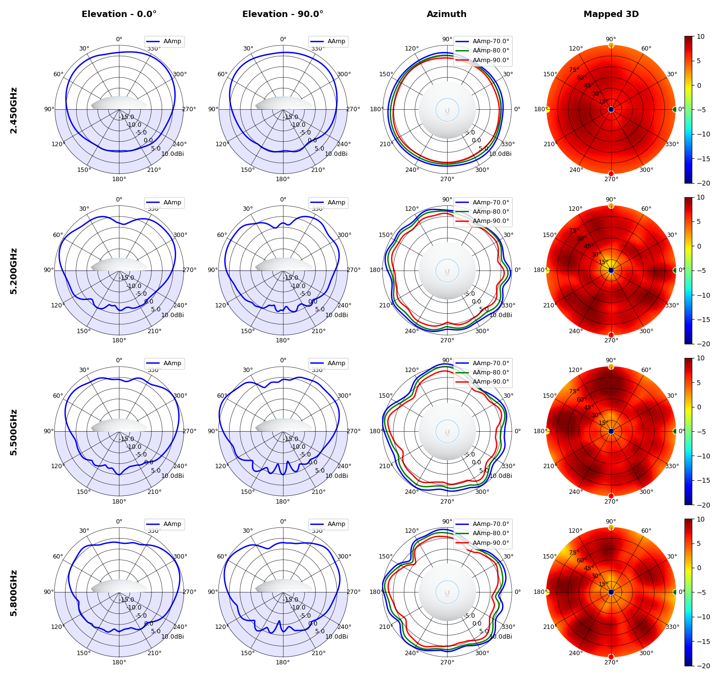
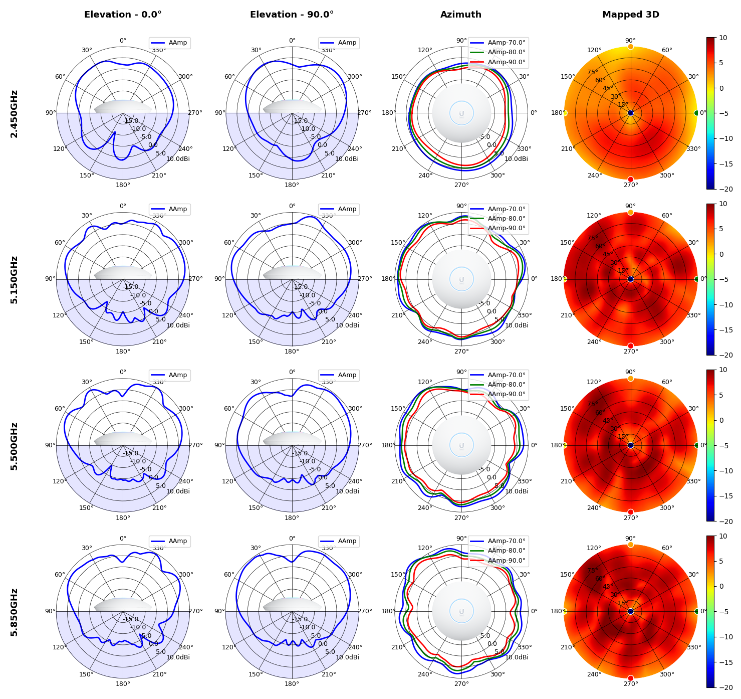
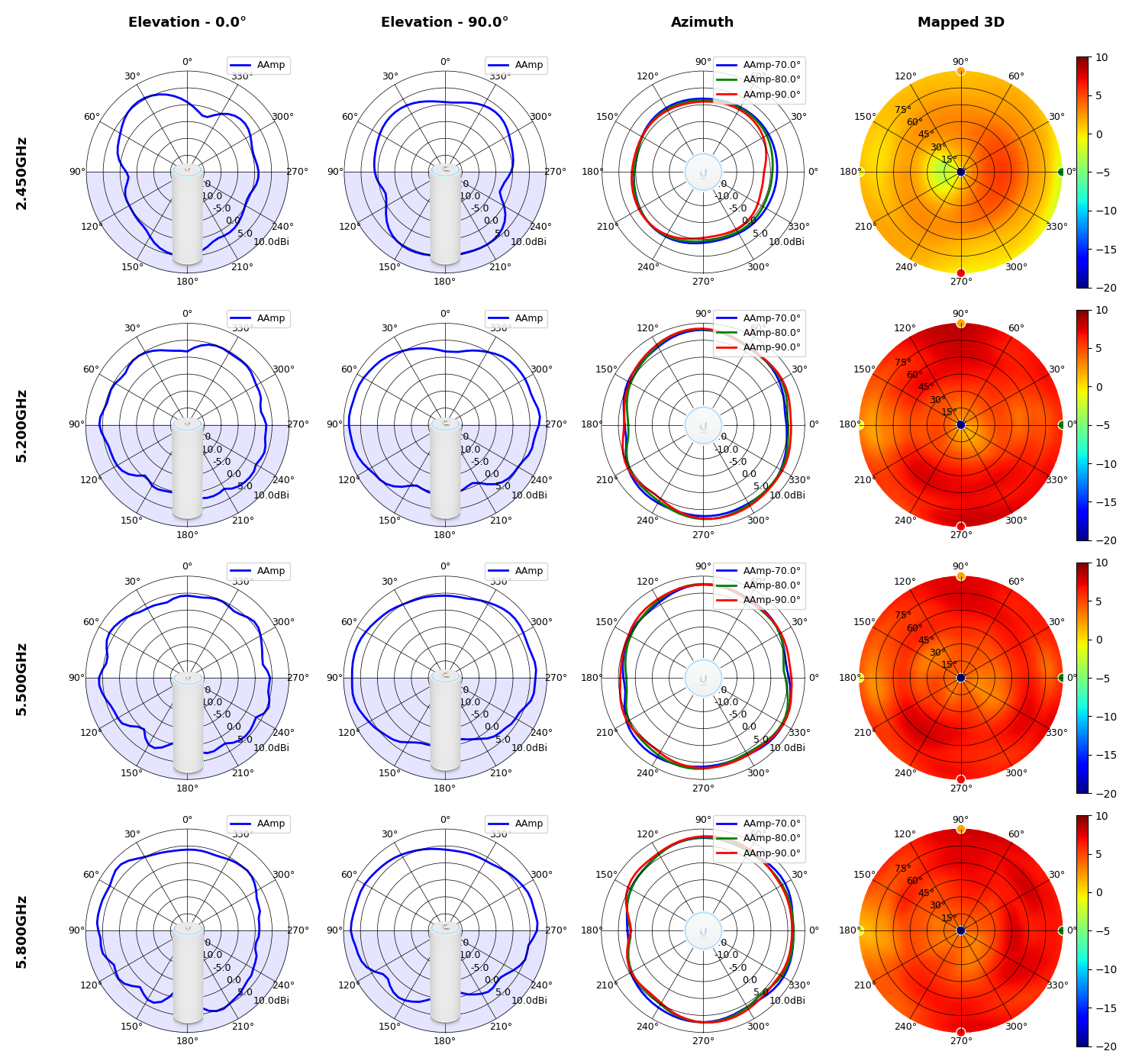
Model Summary Plots
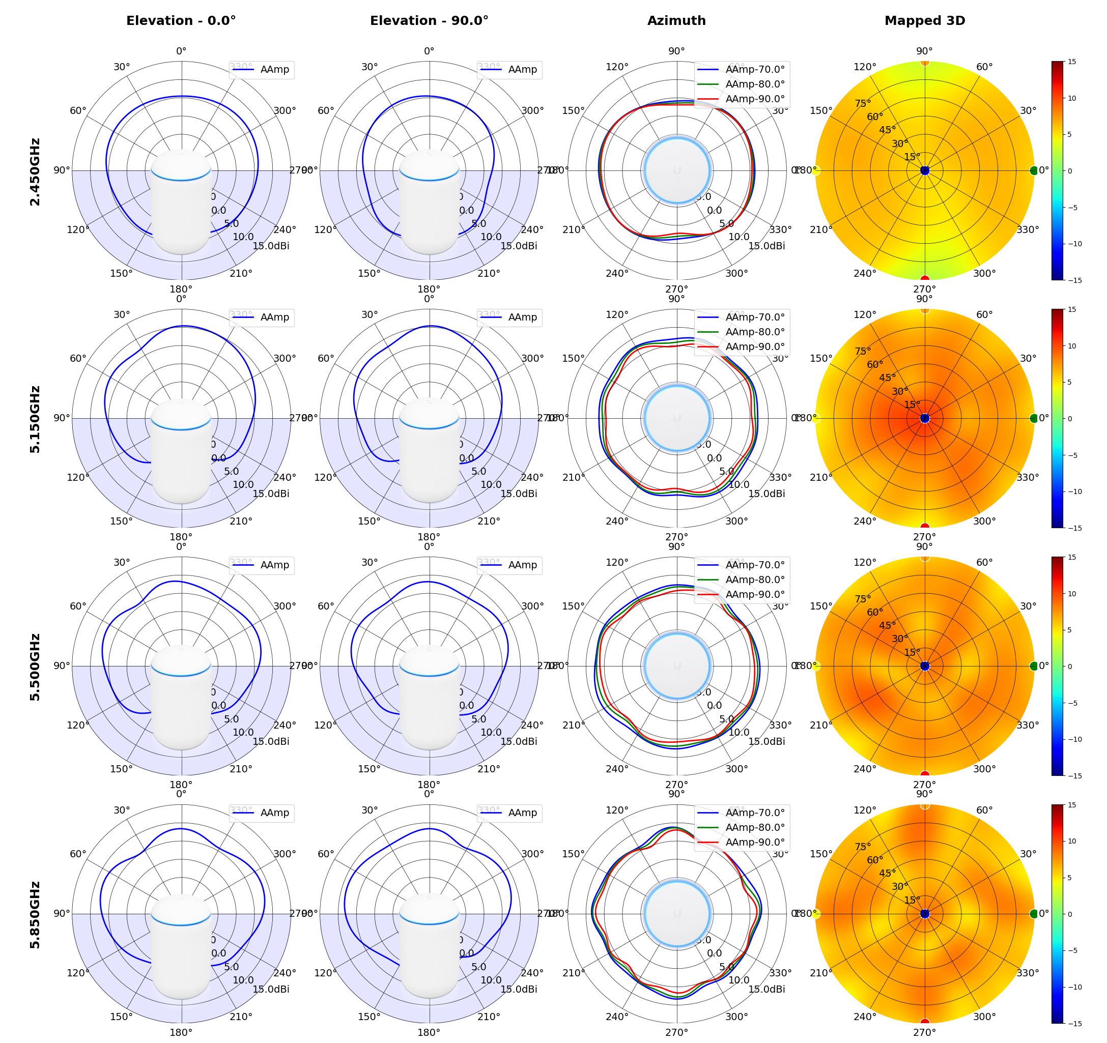
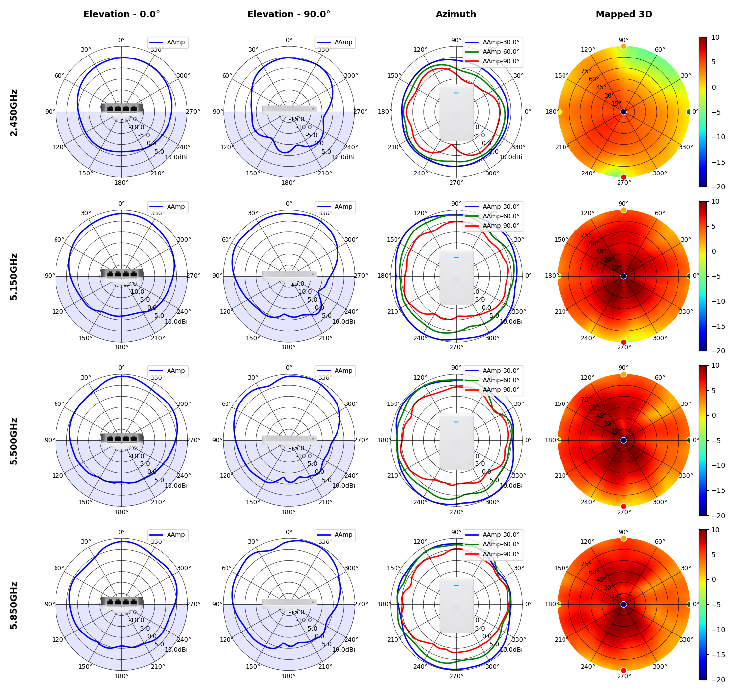
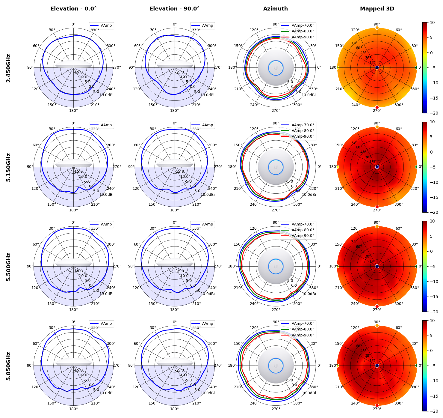
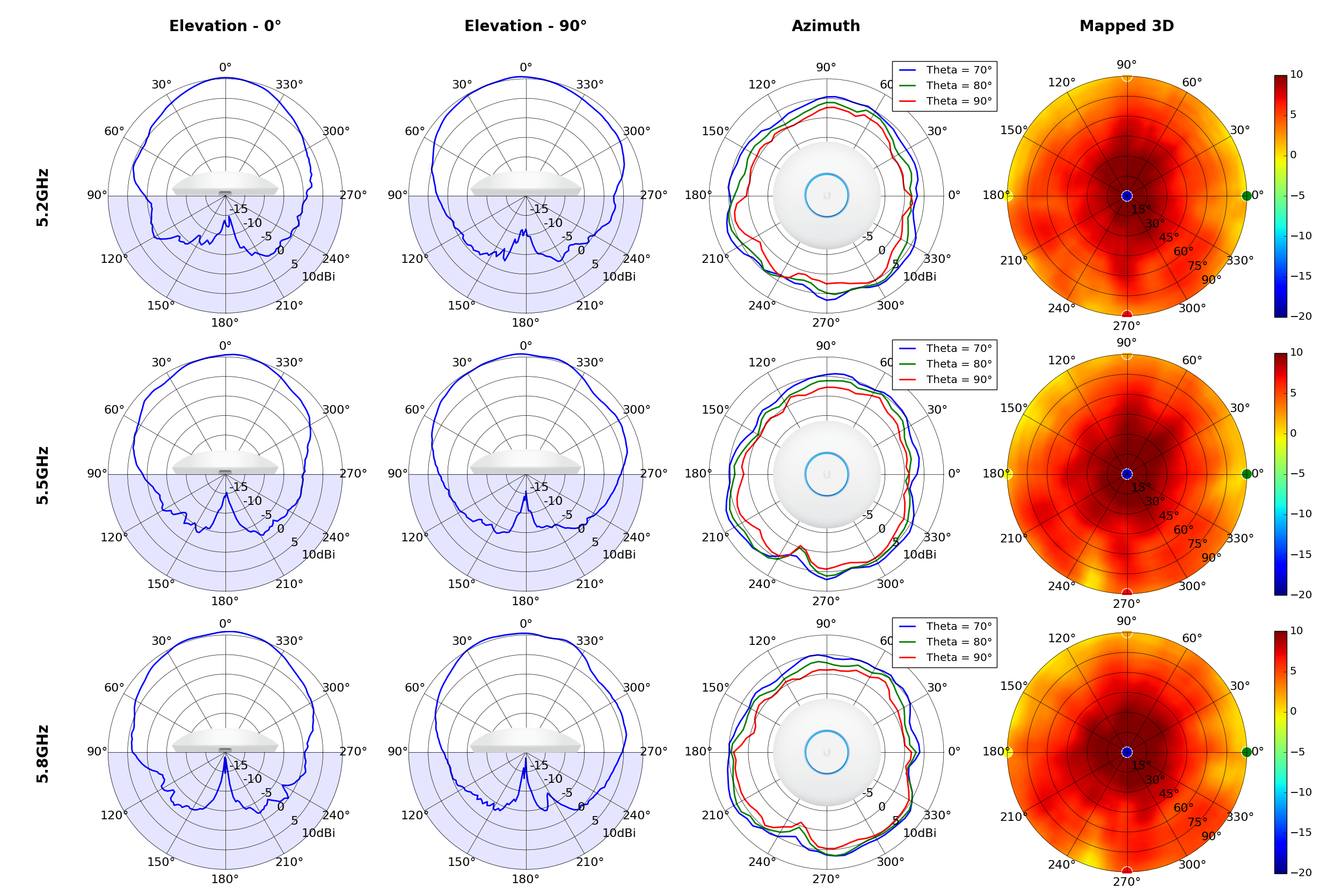
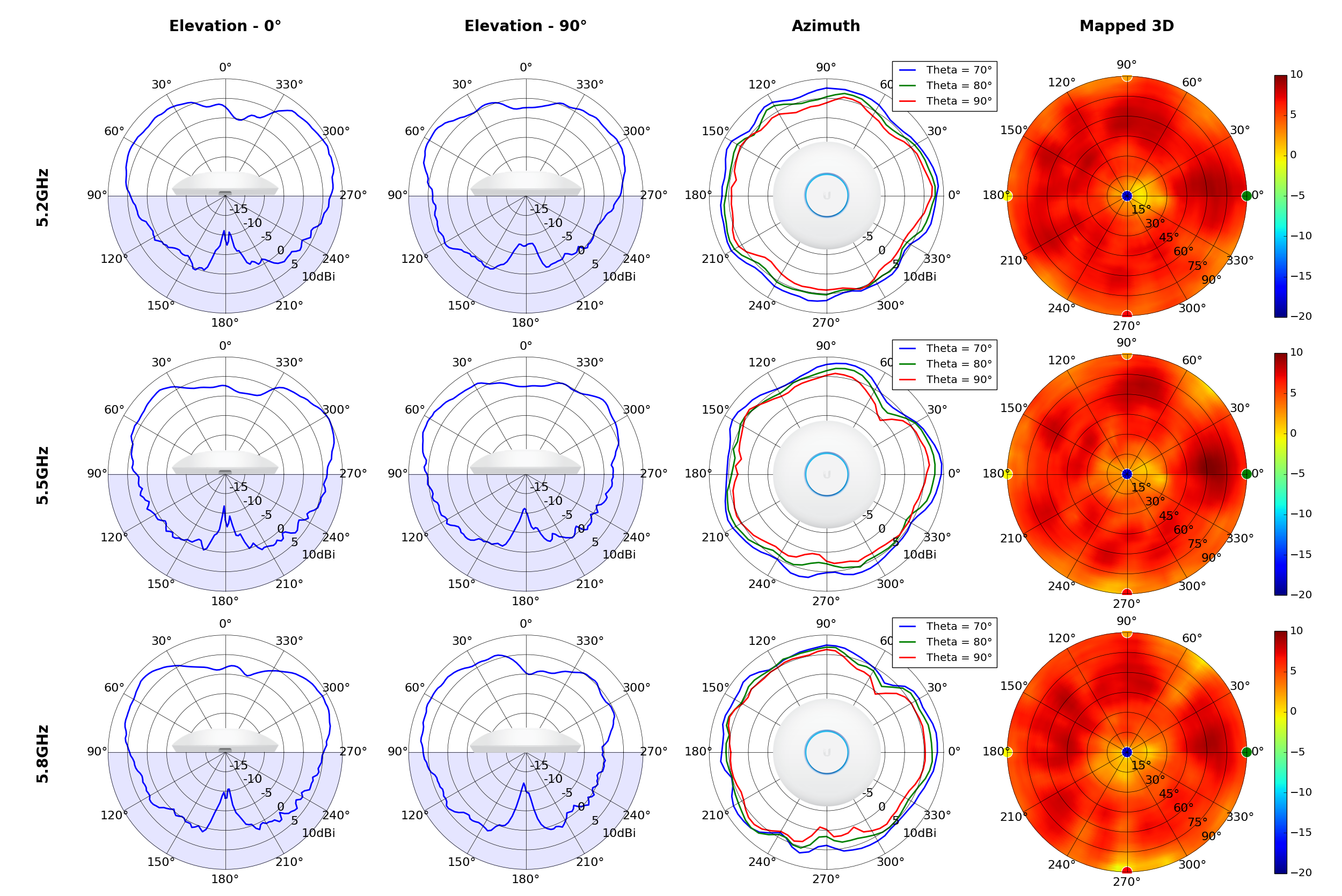
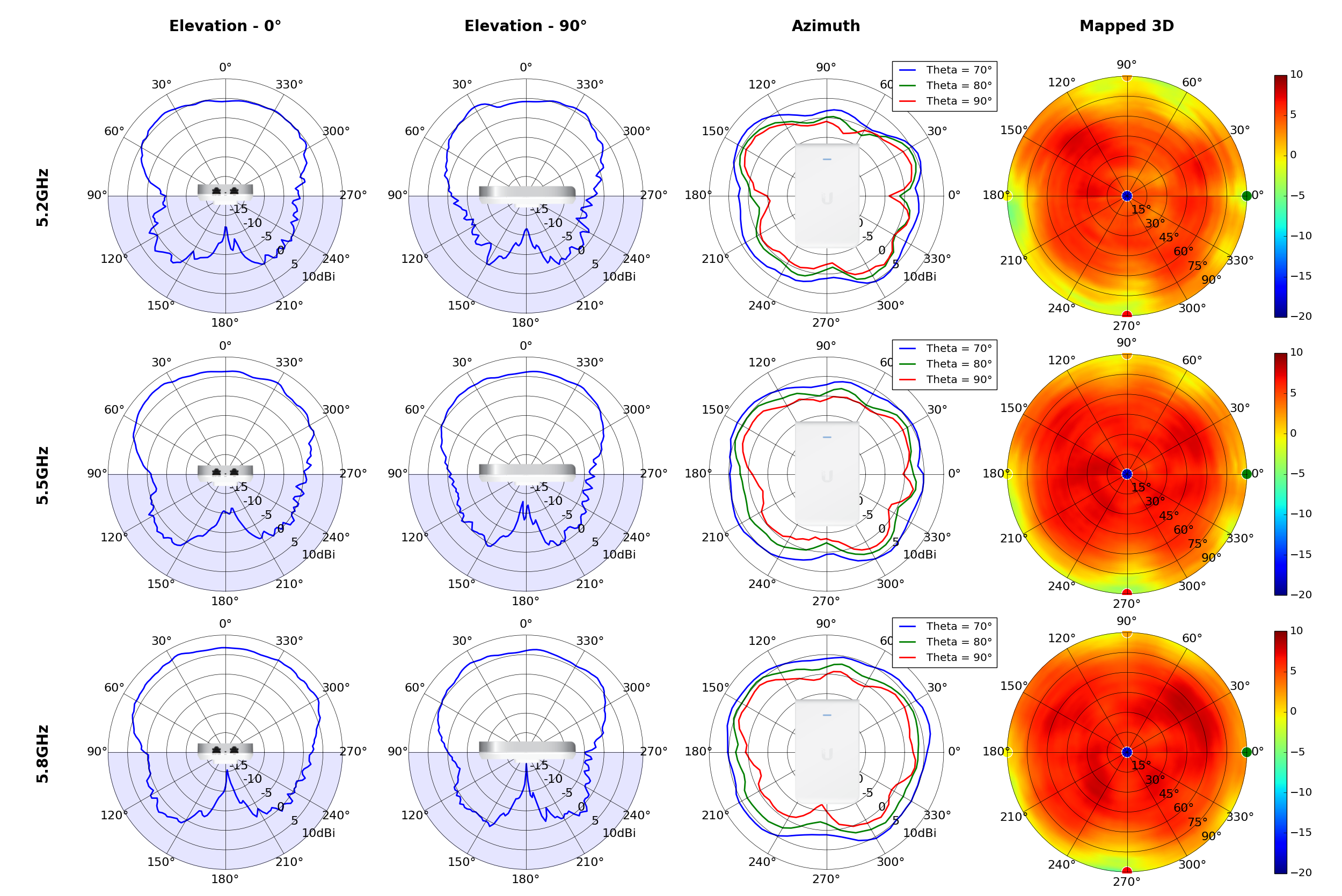
This section includes a graphic summary for each UniFi Access point shown in the table above, portraying radiation plots for Azimuth, Elevation 0°, Elevation 90° and Mapped 3D.U6 Lite

U6 LR
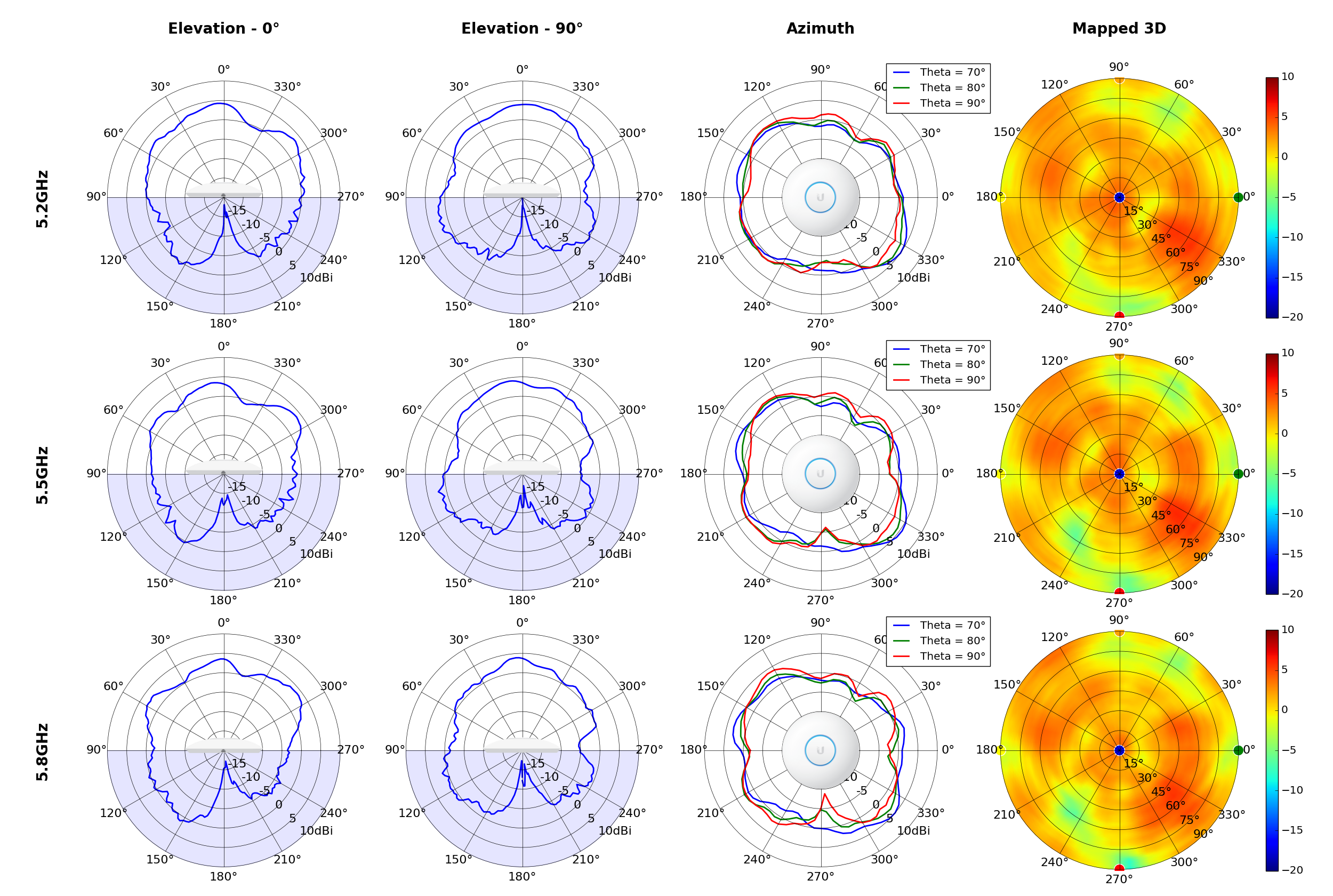
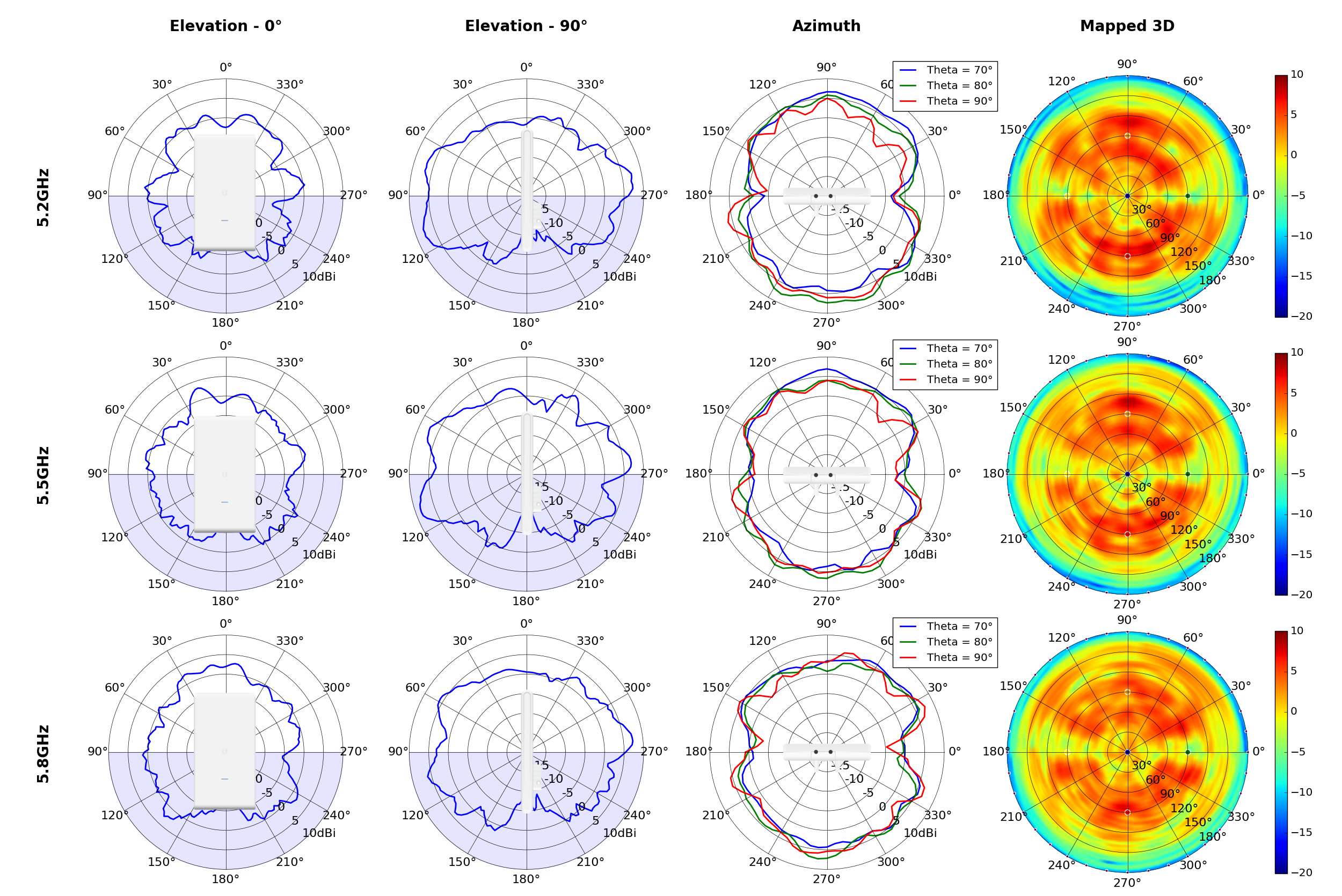
U6 Pro
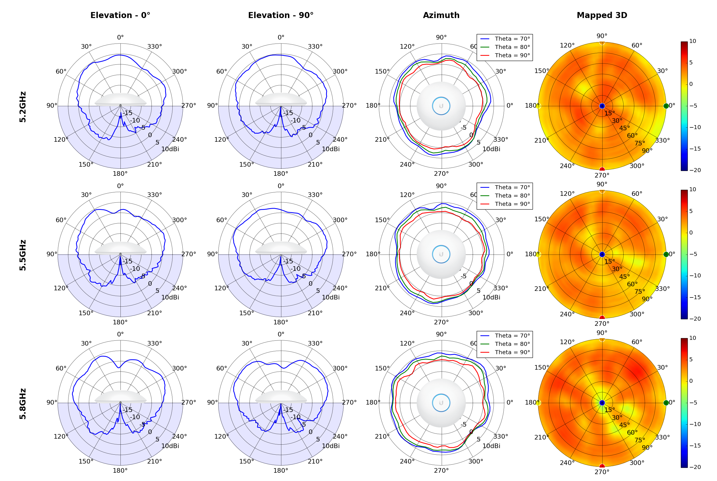
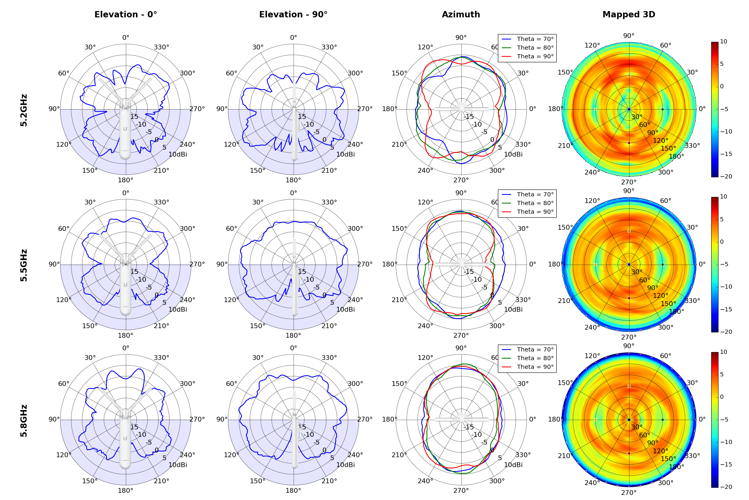
U6 Mesh
UWB-XG
High Gain

Low Gain

UDM
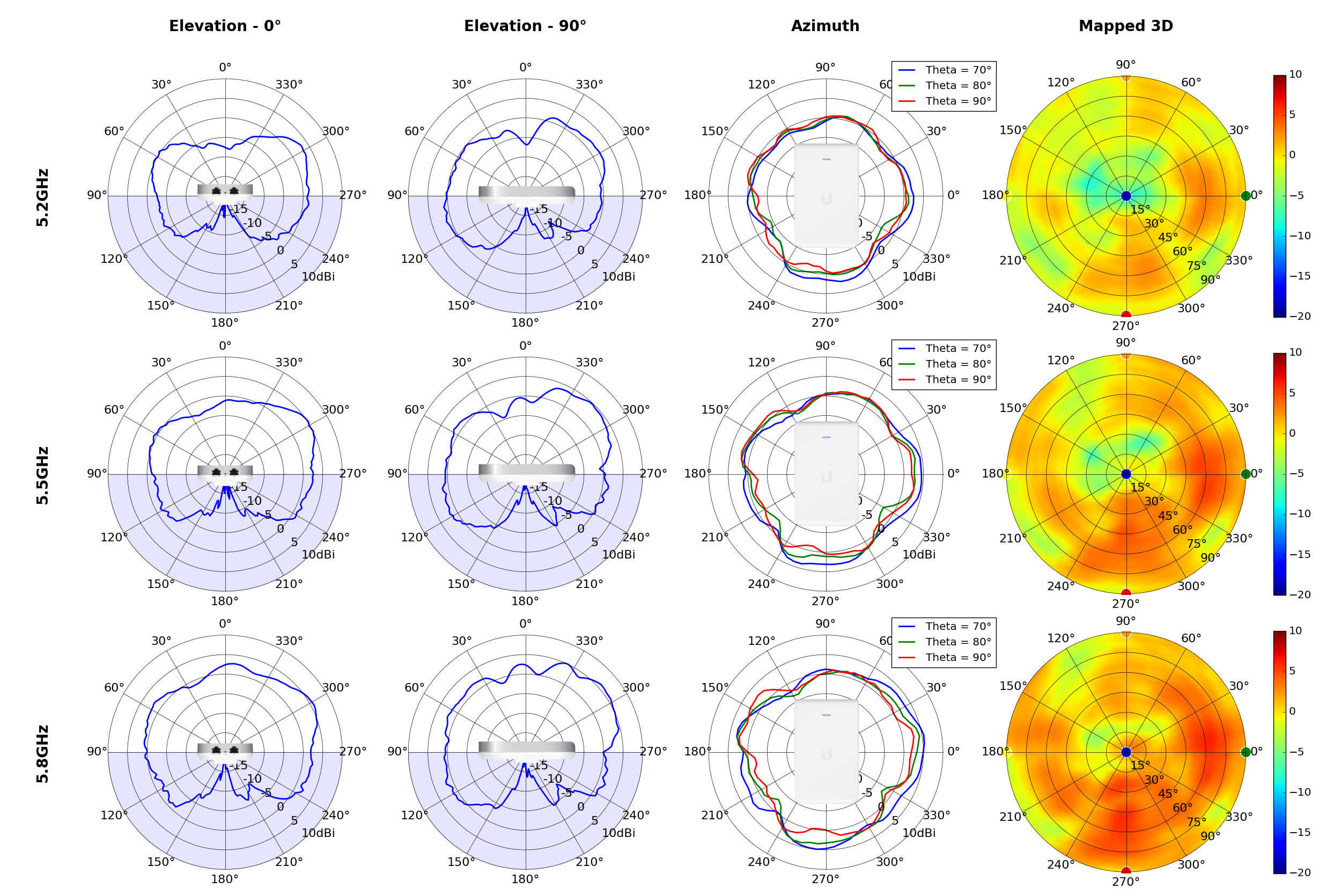
UAP-IW-HD
UAP-FlexHD

UAP-BeaconHD
UAP-nanoHD
UAP-HD
UAP-SHD
UAP-AC-Lite
UAP-AC-LR
UAP-AC-PRO

UAP-AC-IW
UAP-AC-IW-PRO
UAP-AC-M
Note: The antennas for the UAP-AC-M were angled at 45° to generate the plots as shown in the images above.UAP-AC-M-PRO
UMA-D

UAP-XG

Antenna Files (.ant)
Please note the data in the .ant files below was extracted from full model simulations. Clicking on the links in the following table will prompt the immediate download of the .ant file.
| UniFi Access Point Model | Downloadable Antenna Files (.ant) |
| UAP-AC-IW-Pro | UAP-AC-IW-Pro.zip |
| UAP-AC-IW | UAP-AC-IW.zip |
| UAP-AC-Lite | UAP-AC-Lite.zip |
| UAP-AC-LR | UAP-AC-LR.zip |
| UAP-AC-Pro | UAP-AC-Pro.zip |
| UAP-AC-Mesh | UAP-AC-Mesh.zip |
| UAP-AC-Mesh-Pro | UAP-AC-Mesh-Pro.zip |
| UAP-HD | UAP-HD.zip |
| UAP-SHD | UAP-SHD.zip |
| UAP-nanoHD | UAP-nanoHD.zip |
| UAP-IW-HD | UAP-IW-HD.zip |
| UAP-XG | UAP-XG.zip |
| UWB-XG | UWB-XG.zip |
| UMA-D | UMA-D.zip |
| UDM | UDM.zip |
| UAP-BeaconHD | UAP-BeaconHD.zip |
| UAP-FlexHD | UAP-FlexHD.zip |
Source :