If you’re in the market for a new Wi-Fi 6 router, the best deliver reliable coverage to all corners of your home at little cost to get started. If you need extensibility, mesh routers allow you to add additional nodes. But if you want extensive configuration options and an all-in-one solution to cover routing, switching, and home security, consider Ubiquiti’s portfolio. Its UniFi brand covers switches and routers aimed at small businesses, but it turned its attention to the consumer category over the last two years with a decent selection of products. Ubiquiti offers a range of security cameras and video doorbells under UniFi Protect, can easily integrate into an UniFi network. The best part about Ubiquiti’s home security products is they record footage locally and don’t send data to a cloud service, providing better privacy without paying a monthly license to access all the security camera and video doorbell features. So if you’re looking to overhaul your home network, here’s what Ubiquiti has to offer.
All-in-one solution: UniFi Dream Router
 Source: Harish Jonnalagadda / Android Central
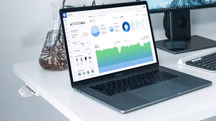
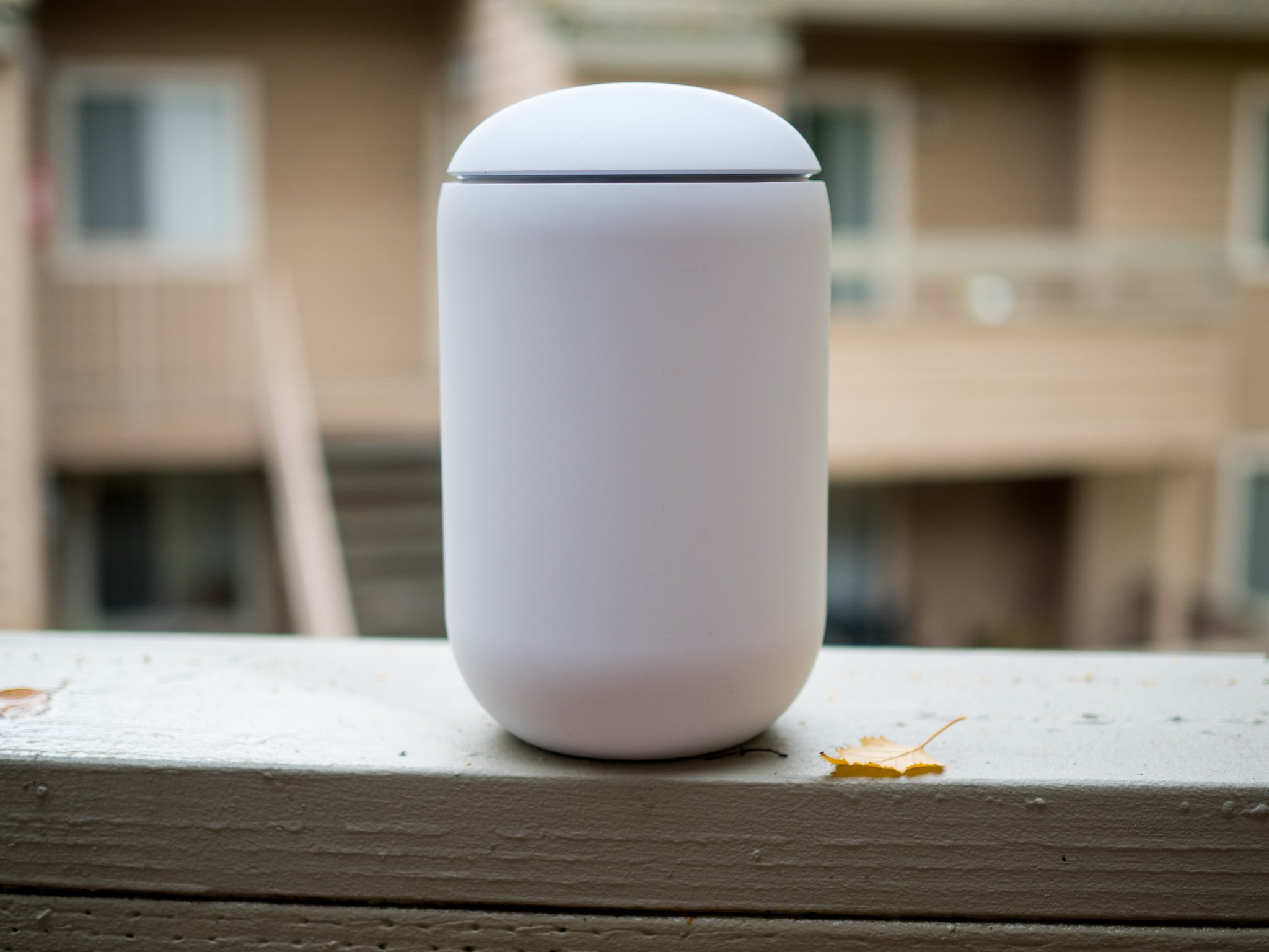
If you don’t want to get a standalone wired router, switch over and add wireless access points, then you’ll want to take a look at Ubiquiti’s unified solutions. The latest offering is the UniFi Dream Router, and it goes up against the best Wi-Fi 6 routers. It’s the second all-in-one device in the UniFi range — after the Wi-Fi 5-based UniFi Dream Machine — and the feature-set you get here is astounding when you consider what it costs.
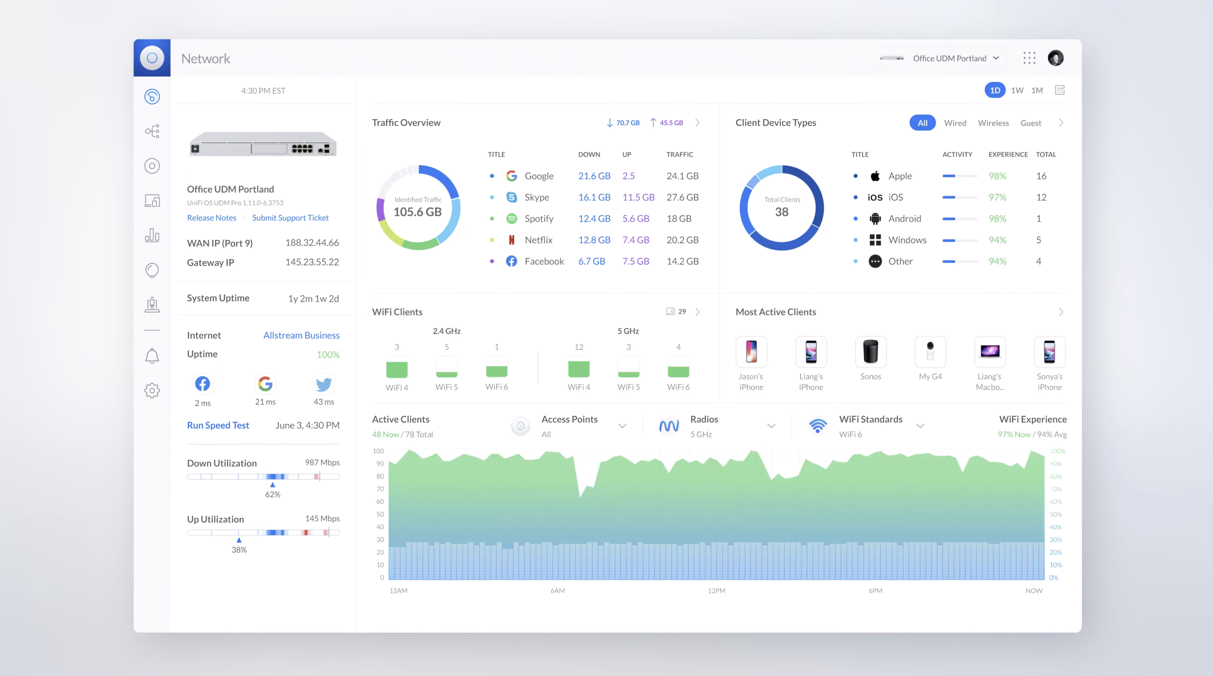
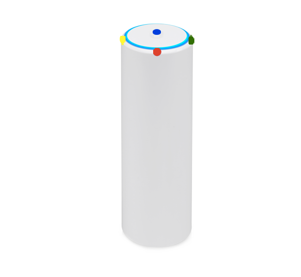
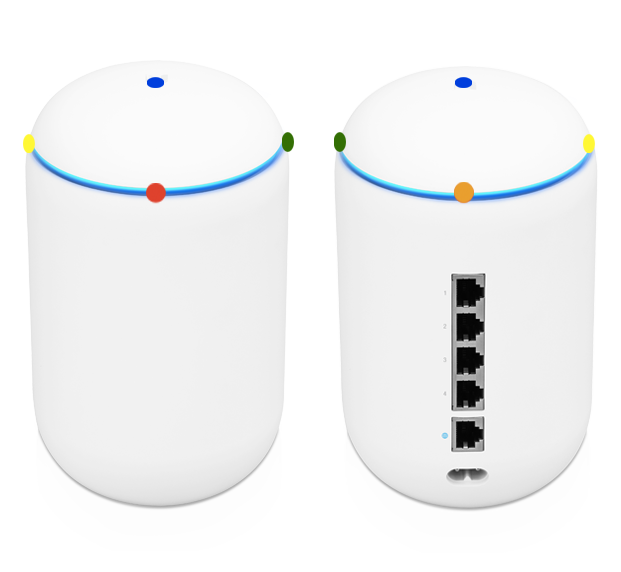
But first, a rundown of the hardware: the Dream Router has a cylindrical design similar to the Dream Machine, but a tiny screen at the front shows real-time network statistics. The router has 4×4 MIMO and goes up to 2.4Gbps with Wi-Fi 6, and it utilizes 160MHz channels. There’s a dual-core CPU, 128GB of storage, an SD card slot, 2GB of RAM, and four Ethernet ports with two offering PoE.
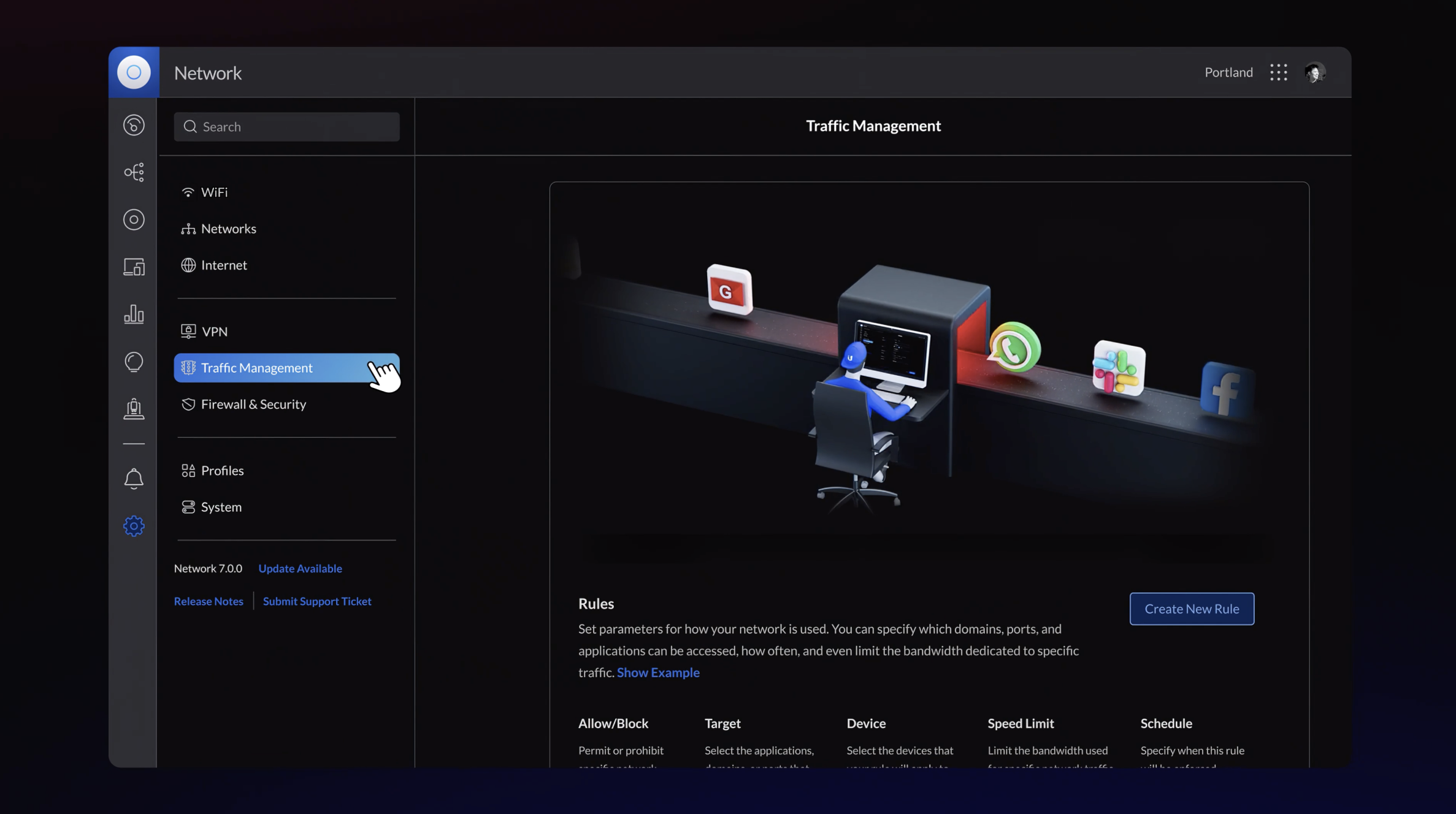
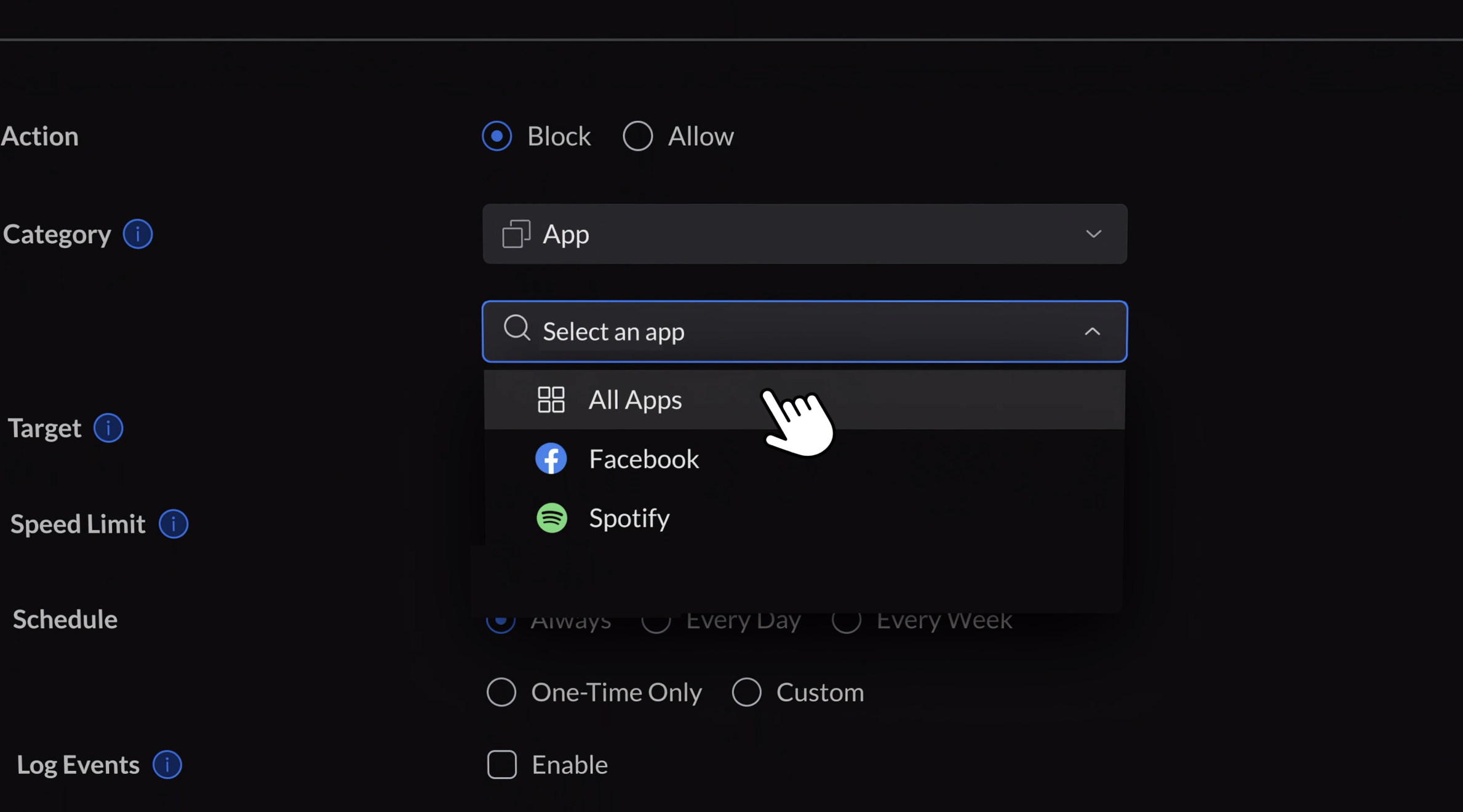
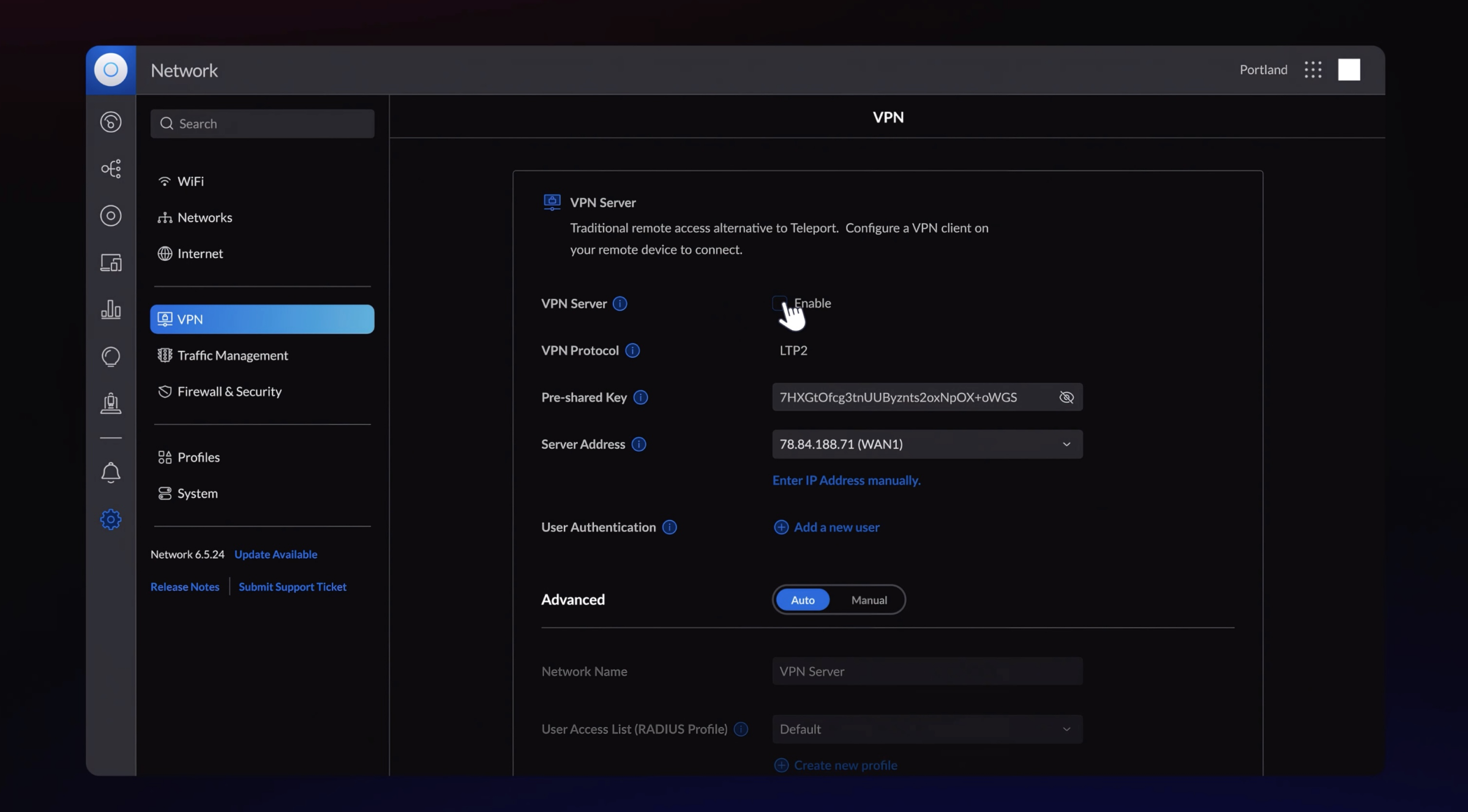
Because it is an UniFi product, the Dream Router has an exhaustive set of configuration options that far exceed most consumer routers. For example, it lets you connect and manage Ubiquiti’s security cameras and video doorbells. It is relatively straightforward to set up from your phone, and if you don’t want to tweak every setting, that’s fine. The options are there should you need them.
Now, there are a few caveats. First, the Dream Router is still in testing and isn’t finalized, and as such, you can only buy it from Ubiquiti’s Early Access store. You’ll have to make a free account to access the store, and while it’s sold out, it’s being restocked regularly. The Dream Router sells out periodically because of its price: $79.
For under $100, there isn’t another router that delivers anywhere close to the same set of features as the Dream Router, and with the router estimated to debut for a lot more once it hits the regular sales channel, now is the best time to pick it up.
UniFi Dream Router
With 4×4 MIMO and 2.4Gbps bandwidth over Wi-Fi 6, four Gigabit Ethernet ports with two PoE ports, and a screen at the front for monitoring real-time traffic, the Dream Router is the ultimate value.
Routing: UniFi Dream Machine Pro
 Source: Harish Jonnalagadda / Android Central
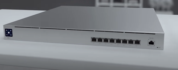
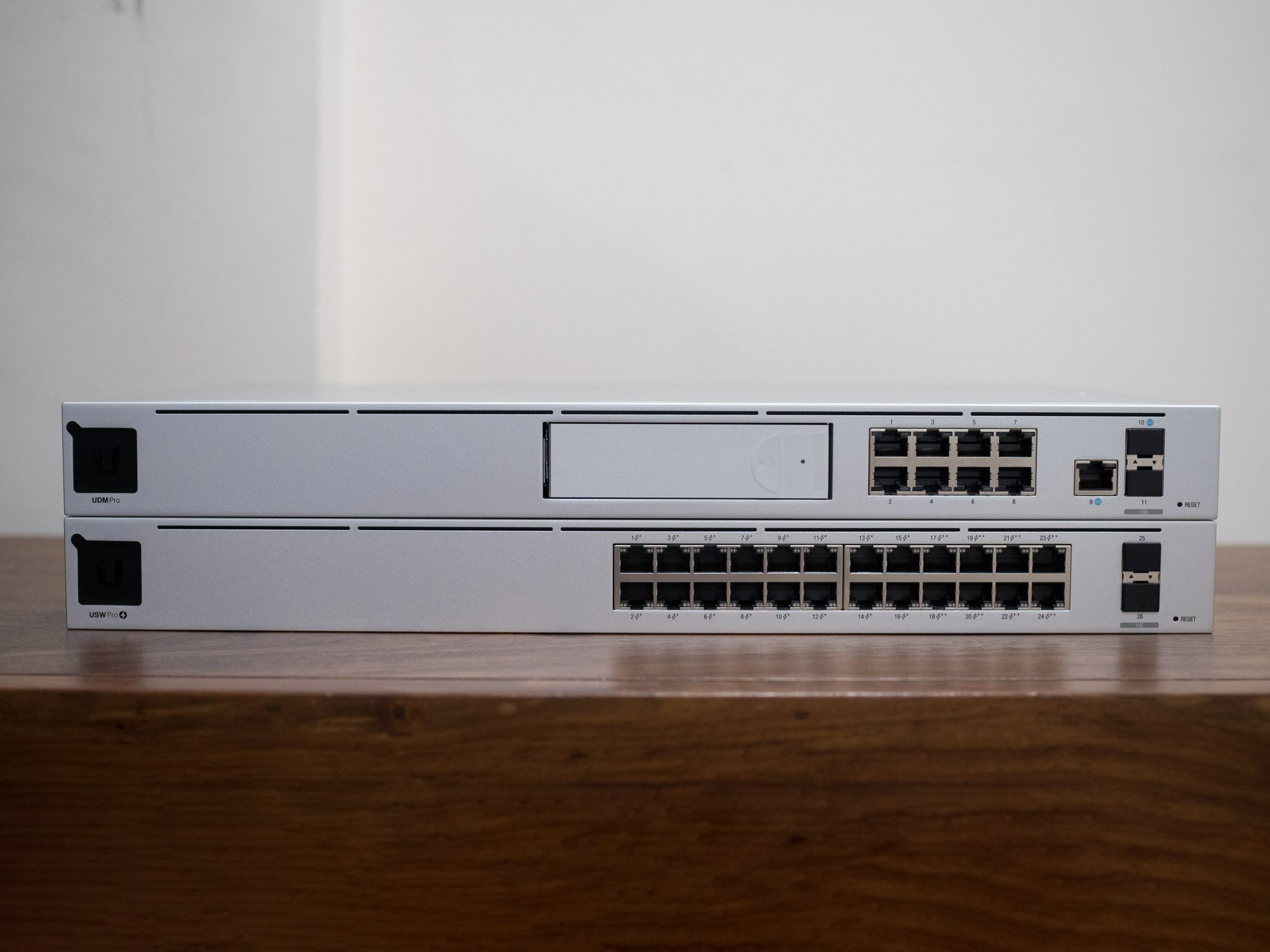
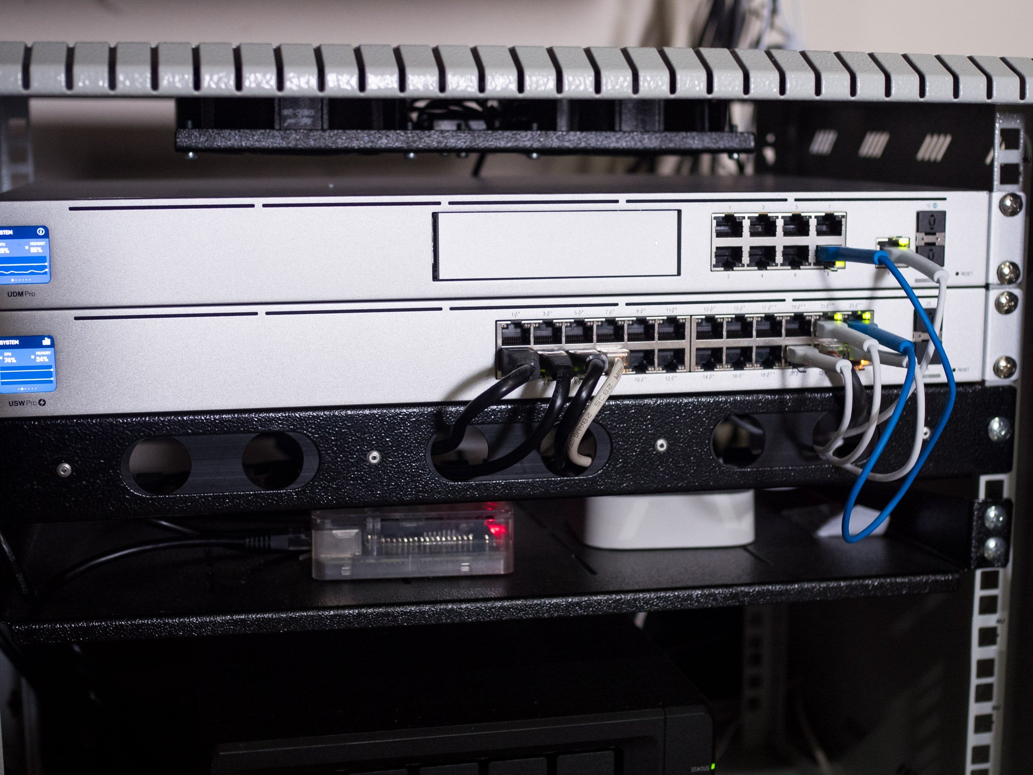
If you want to use a standalone router for managing your home network, you should take a look at the UniFi Dream Machine Pro (UDM Pro). I switched to the UDM Pro last year, and it has been a revelation. However, unlike the Dream Machine or Dream Router, the UDM Pro is a 1U rack-mounted solution, so you will need a rack server if you want to go down this route.
The UDM Pro is designed to be a wired router, so you’ll have to buy a switch and a wireless AP to connect your wireless devices like phones, tablets, and notebooks. Now, the standout feature with the UDM Pro is that it has a 3.5-inch HDD slot to facilitate network video recording (NVR), so if you want to add Ubiquiti’s security cameras to your network, this is the ideal way to go. In addition, you can slot in a 4TB drive in the UDM Pro and access locally-stored recordings going back weeks and months.
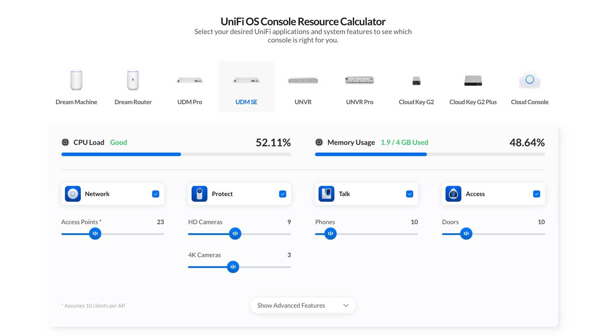
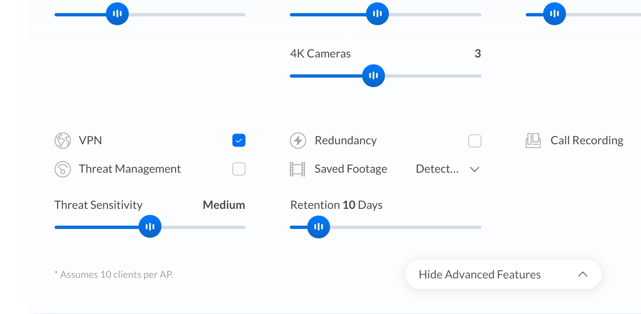
As for hardware, the UDM Pro has a built-in switch with eight Gigabit ports with a 1GbE backplane, 10Gbps SFP+ ports, and a quad-core CPU with Cortex-A57 cores. It includes the full suite of UniFi OS applications, including UniFi Network for switching, UniFi Protect for security cameras, UniFi Talk for VoIP, and UniFi Access for managing door access in a small office environment. The UDM Pro also offers intrusion detection and prevention features that block access to malicious websites.
Having used the UDM Pro extensively for the last year, the only downside I can think of is that it lacks built-in PoE ports. So when you’re connecting Ubiquiti’s wireless access points, you will need to buy an additional PoE injector.
UniFi Dream Machine Pro
The UDM Pro sits at the heart of a prosumer UniFi install. The rack-mounted router comes with an 8-port switch and 10G SFP+ ports, a 3.5-inch drive tray to use as a network video recorder, and class-leading threat management features.
Switching: UniFi Switch 24 PoE
 Source: Harish Jonnalagadda / Android Central
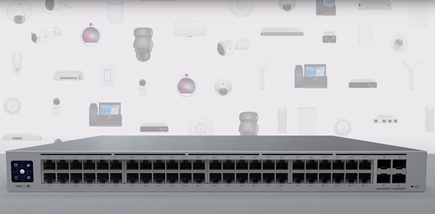
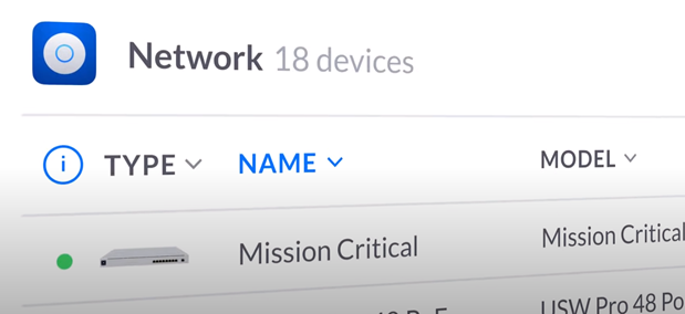
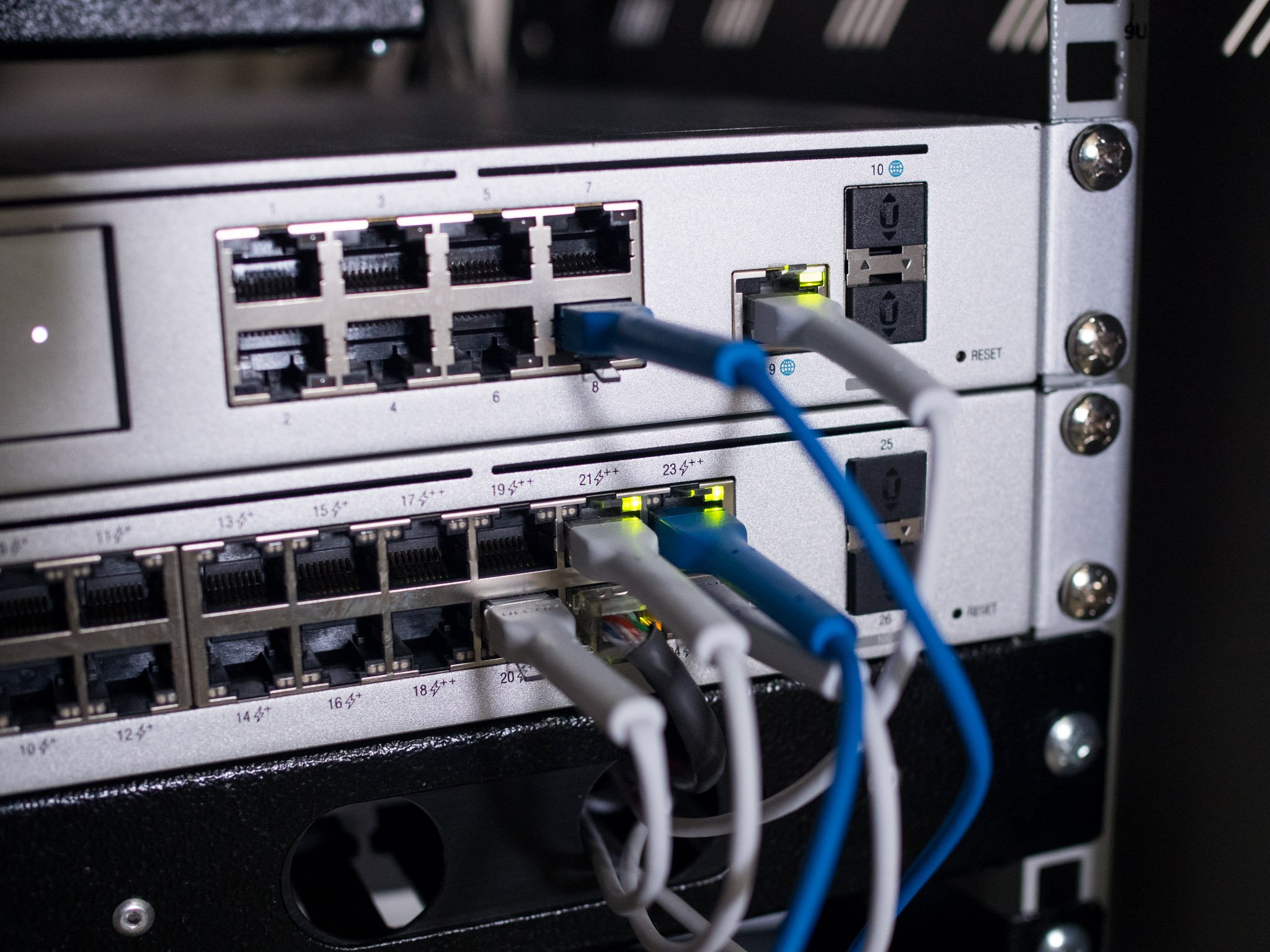
While I have over 30 devices connected to the wireless access points in my home at any given time, I use wired connectivity for the devices that I use the most, including the work machines, TVs, and the PS5. So while the UDM Pro has an eight-port switch, I find that a 24-port option is the best way to go, particularly if you’re going to connect a lot of security cameras. For context, I’m currently using over a dozen ports on my Switch Pro 24 PoE.
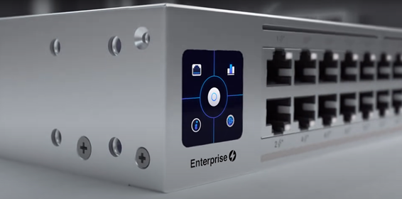
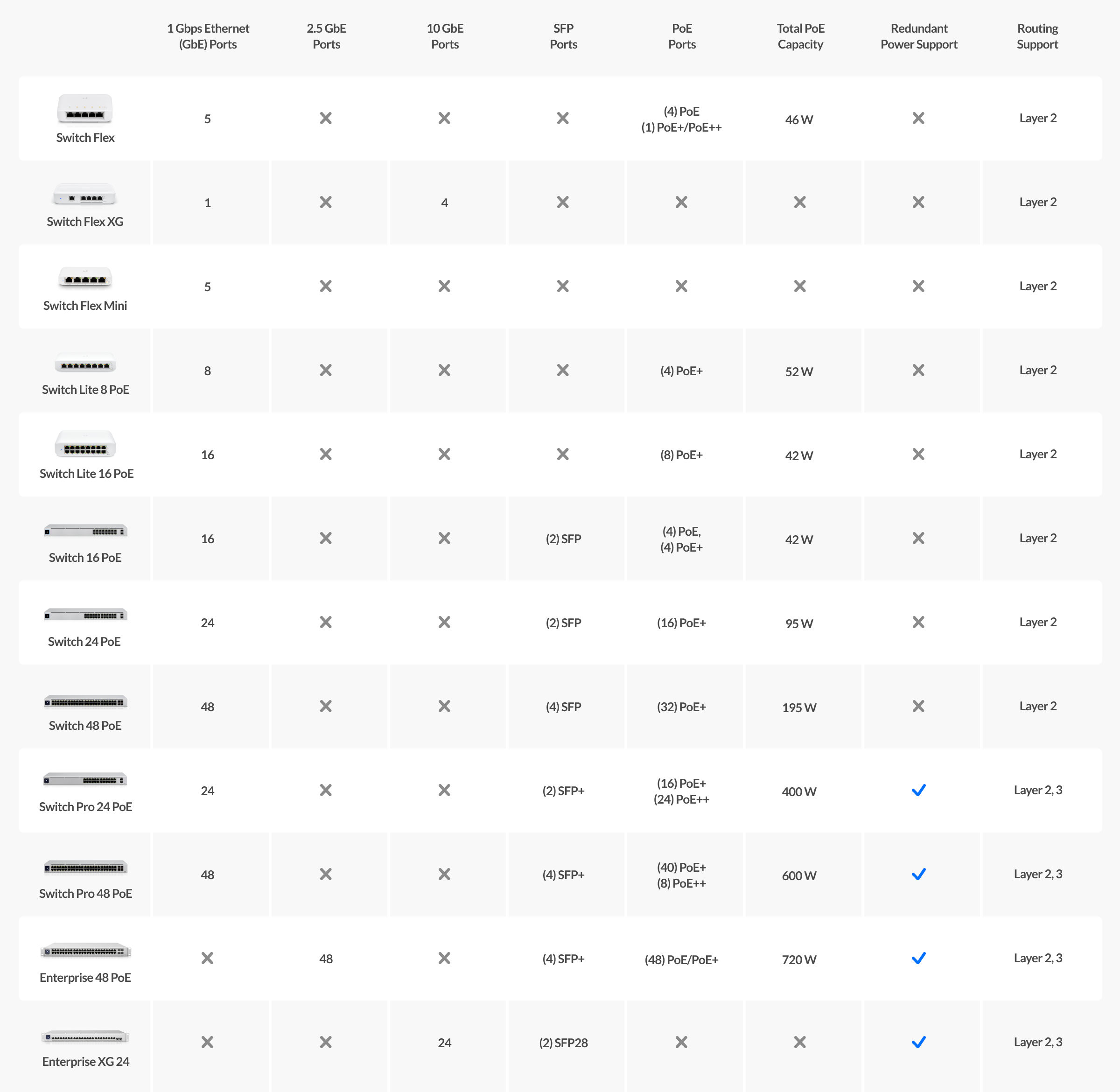
As for the switch, the Switch Pro 24 PoE is a fantastic choice, but at $699, it is also very costly. My recommendation would be the standard Switch 24 PoE; it is a 24-port switch with 16 Gigabit PoE+ ports with a total power budget of 95W alongside eight Gigabit ports. Like the UDM Pro, it is a 1U rack-mountable solution, and you get a small screen on the left for viewing real-time statistics.
The 95W power budget is more than adequate for the wireless access points and security cameras, and at $379, the Switch 24 PoE costs nearly half as much as the Pro version, and while you miss out on 10Gbps SFP+ ports, it has most of the essentials covered. If you don’t want a rack-mounted solution, you should look at the Switch Lite 16 PoE, a 16-port switch with eight PoE+ ports.
UniFi Switch 24 PoE
If you need more ports for wired connections, the Switch 24 PoE is the ideal option. It has 16 802.3at PoE ports with a cumulative power budget of 95W and can easily accommodate a slate of wireless access points and security cameras.
Wireless: UniFi Access Point Wi-Fi 6 Lite
 Source: Ubiquiti
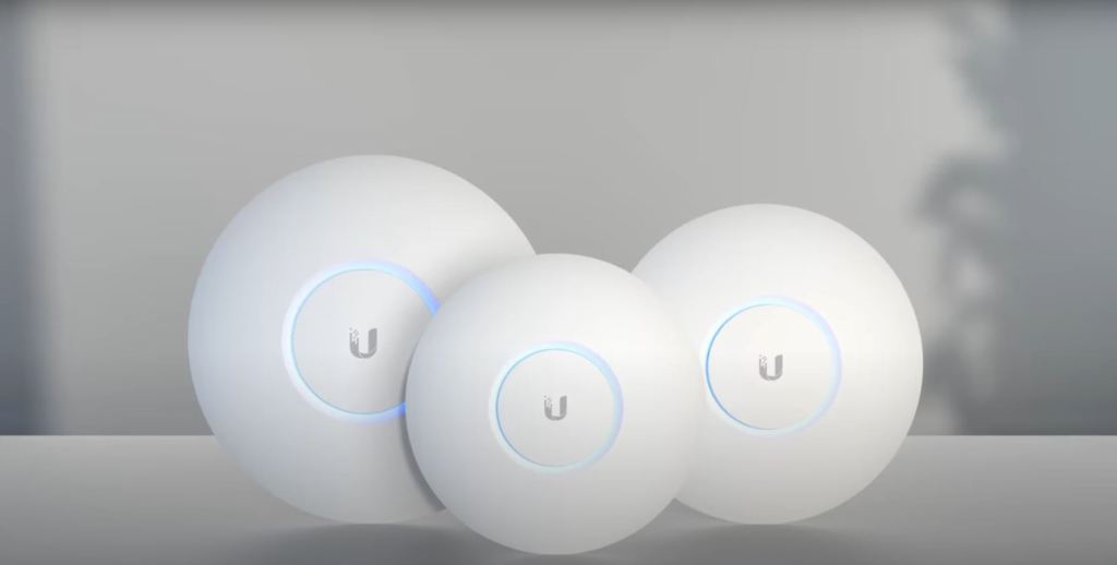
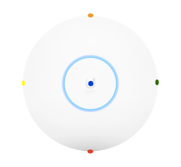
With a wired router and switch sorted out, you’ll need a wireless access point so wireless devices like phones and tablets can connect to your home network. Ubiquiti has three options in this area: Wi-Fi 6 Lite, 6 Pro, and 6 Long Range. As the name suggests, all three are based on Wi-Fi 6, and they share a similar design.
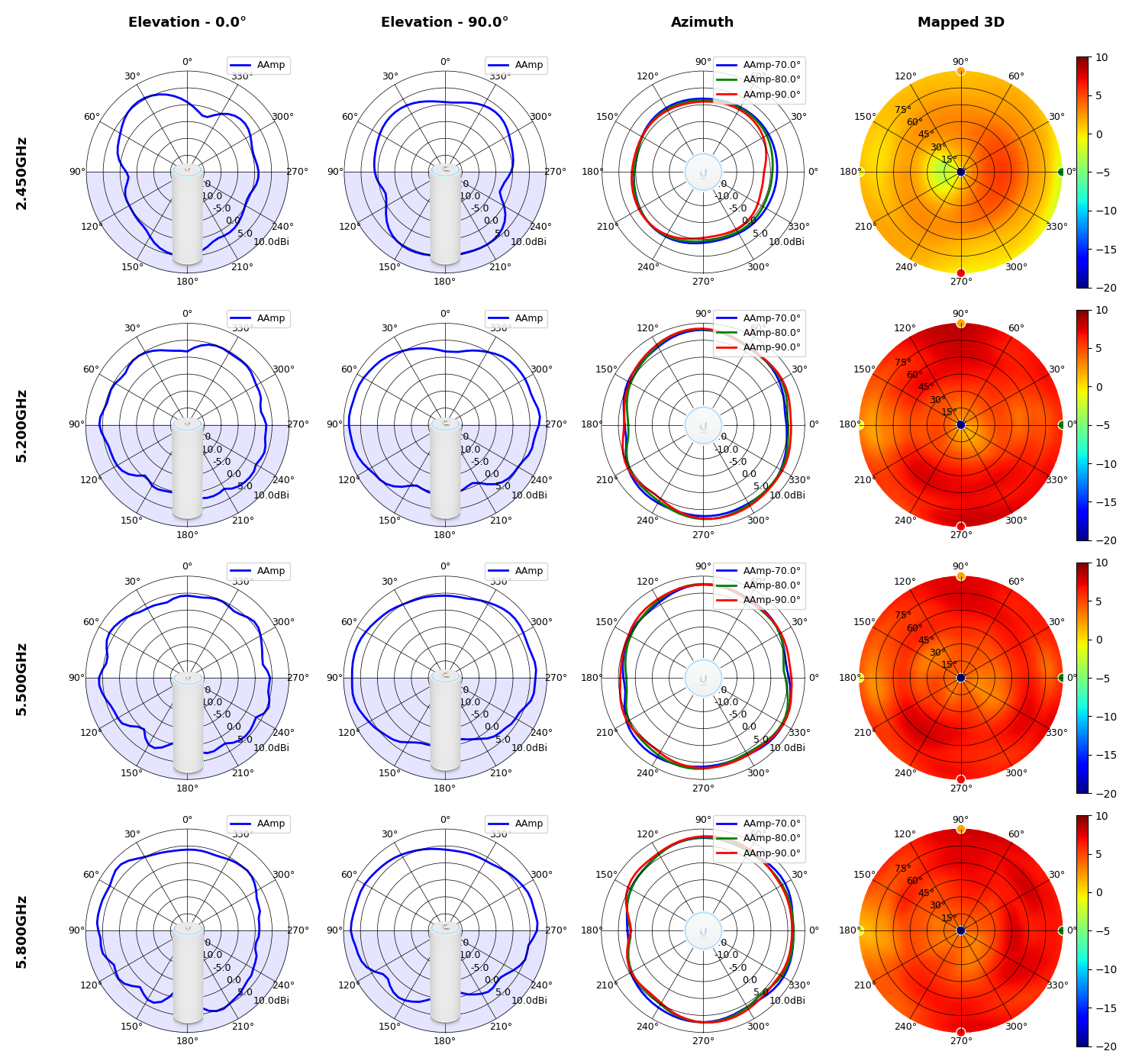
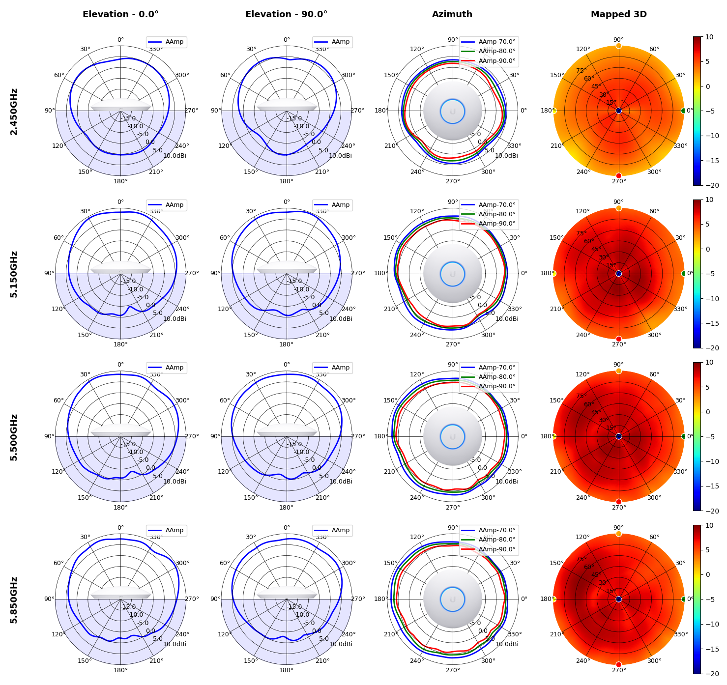
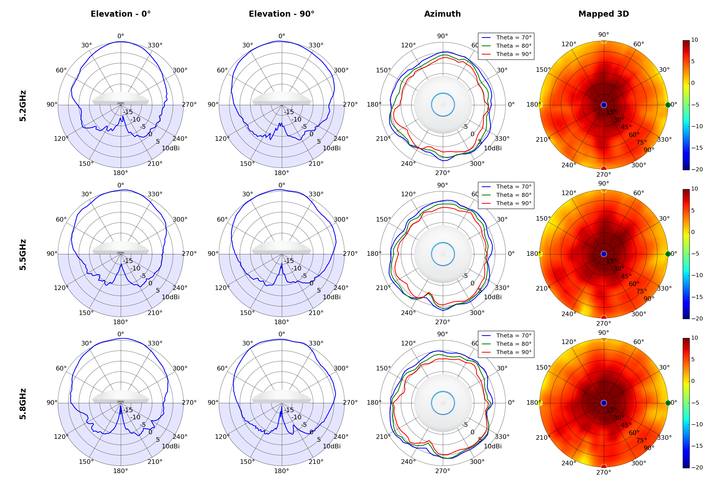
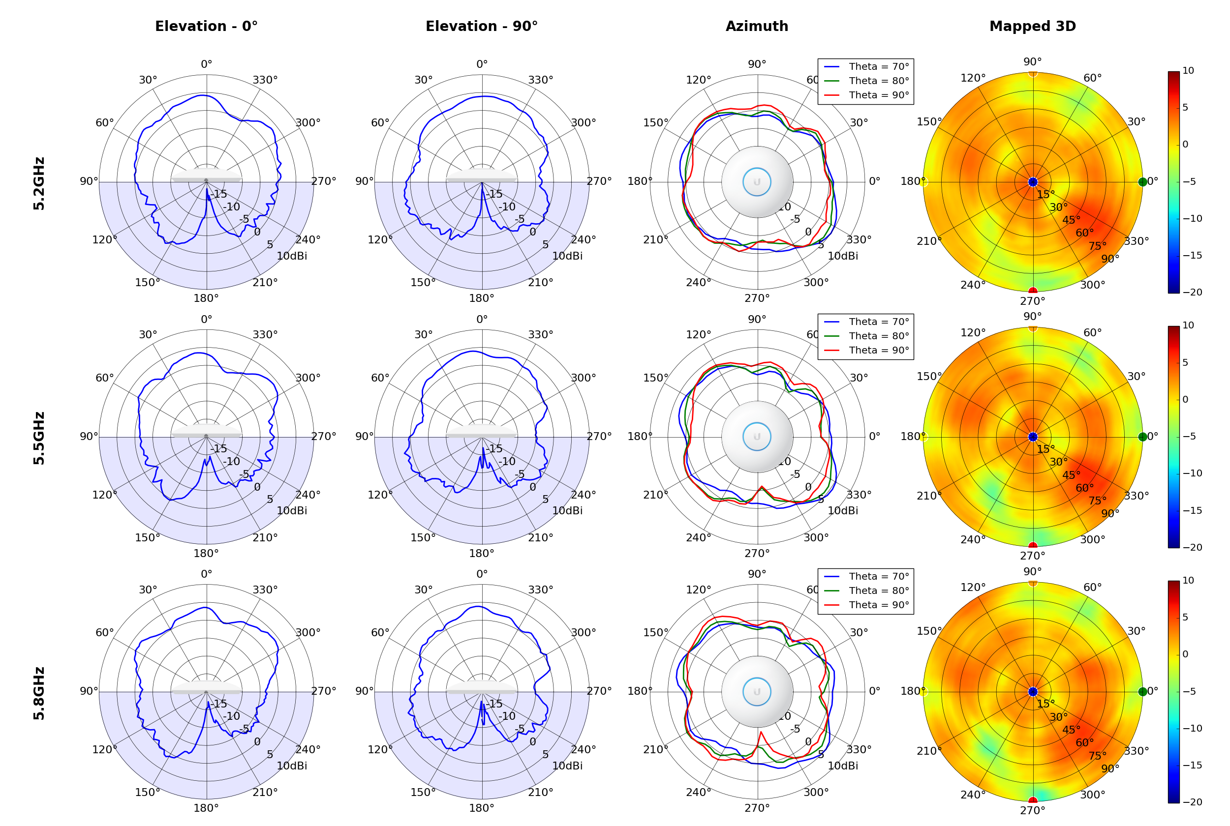
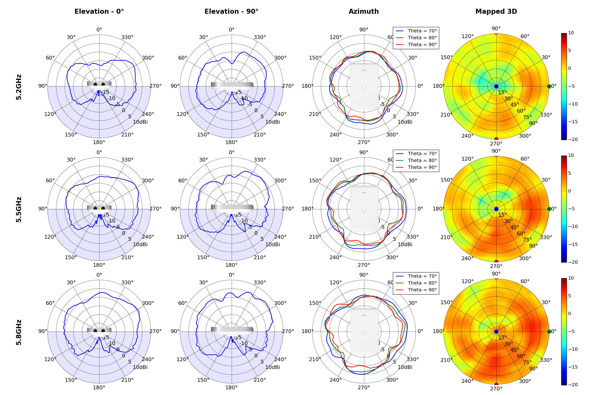
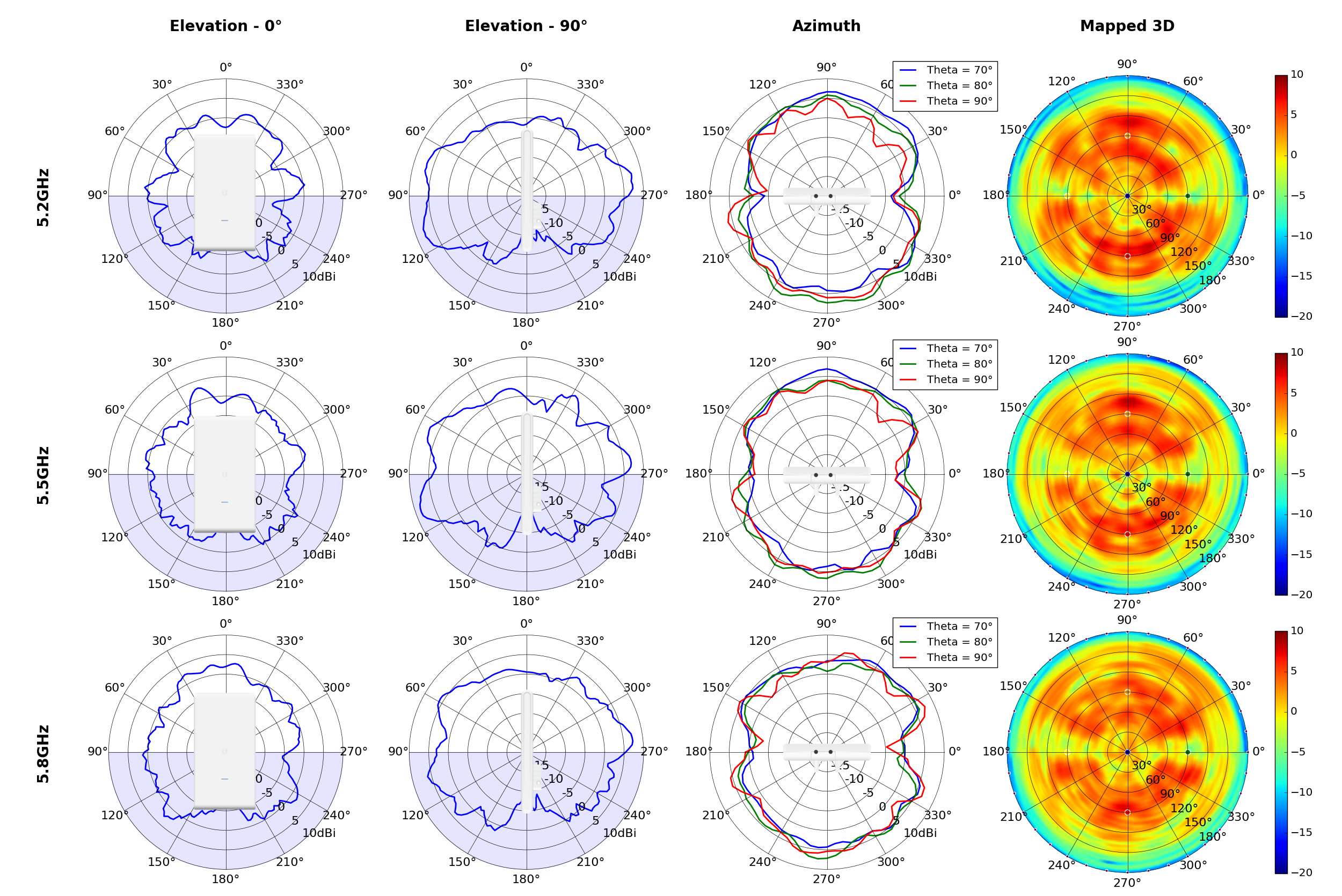
These APs work best when mounted on the ceiling or the wall as the antennae are positioned sideways. The $99 Wi-Fi 6 Lite has 2×2 MIMO and goes up to 1.2Gbps on the 5GHz band, with a gain of 3dBi. The $149 Wi-Fi 6 Pro and $179 Wi-Fi 6 Long Range have IP54 ratings, draw power using the 802.3at PoE+ standard, and are designed for indoor and outdoor use.
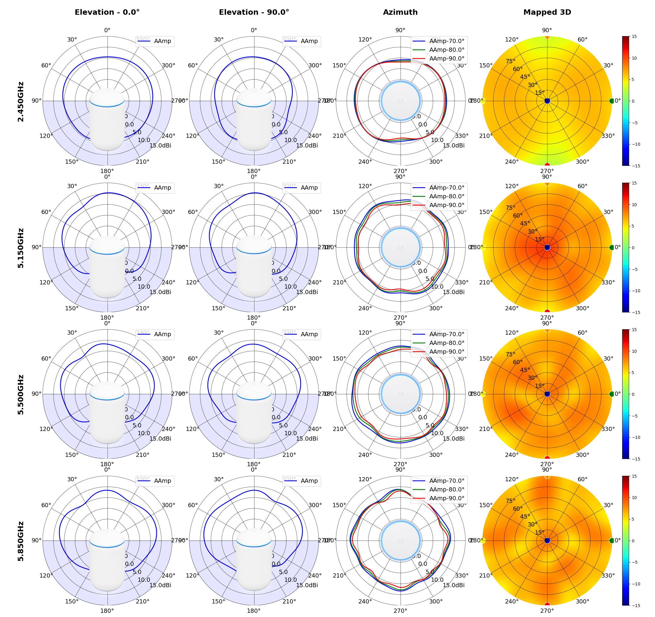
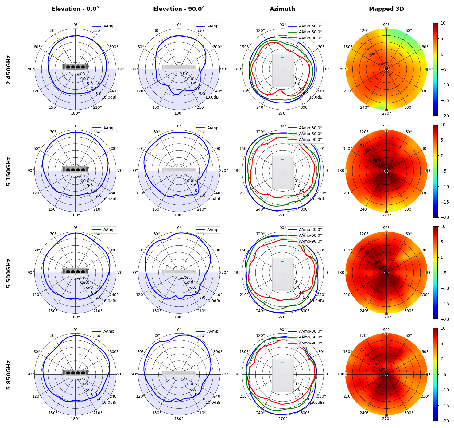
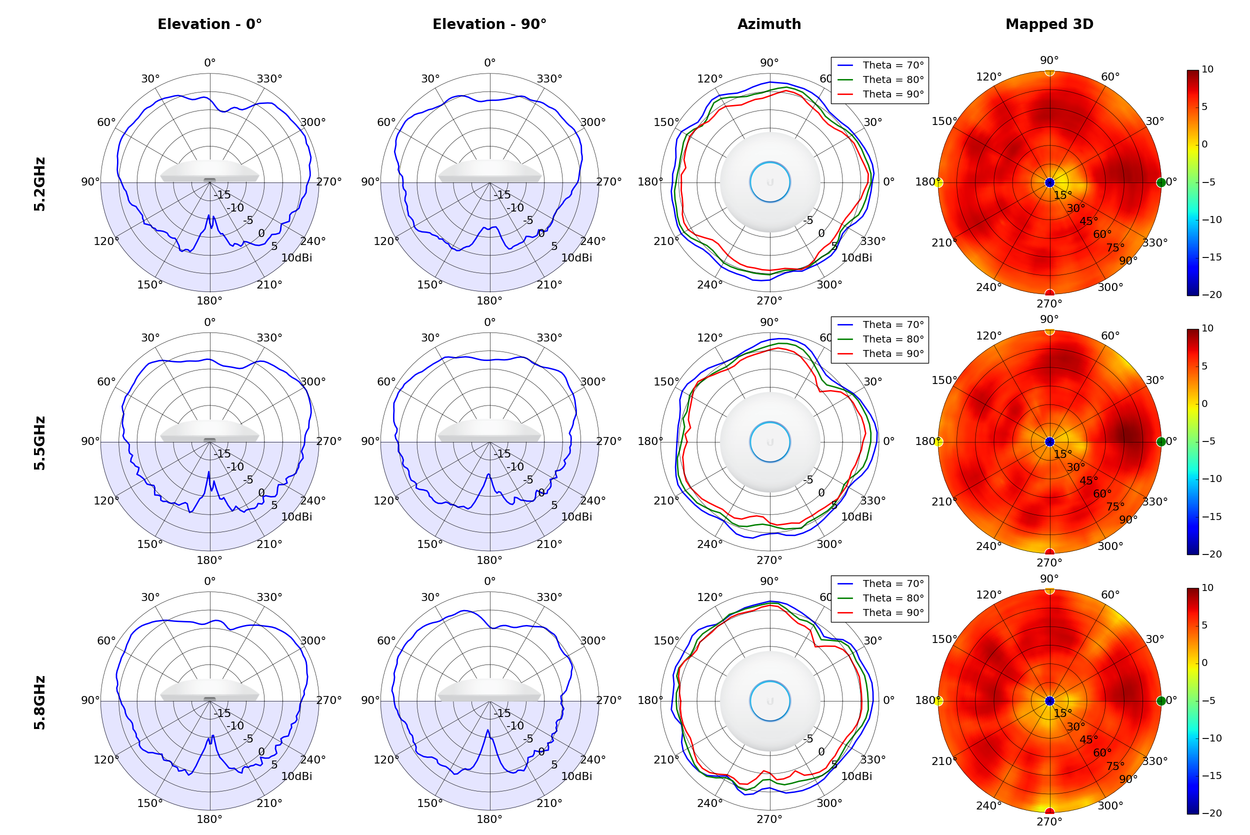
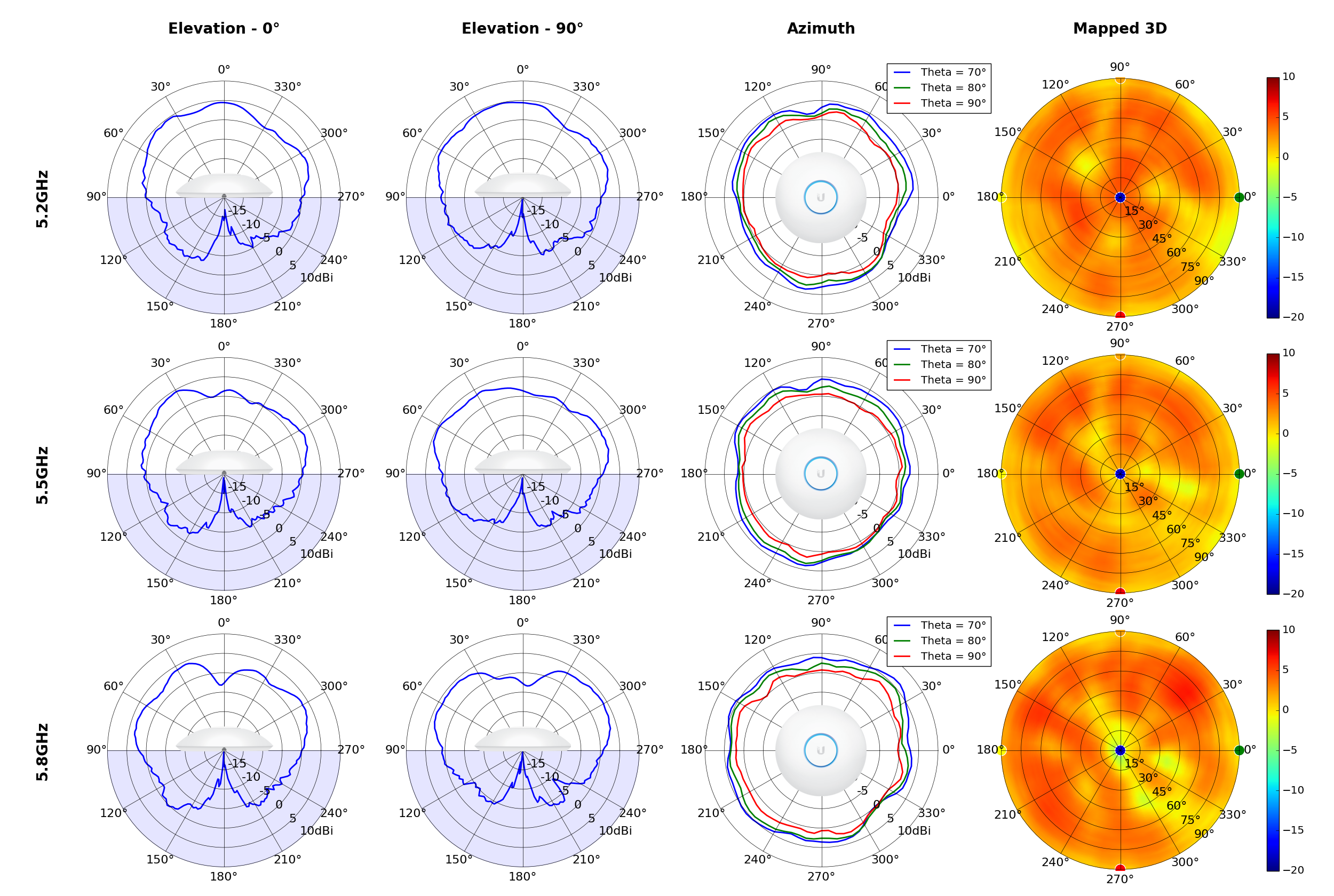
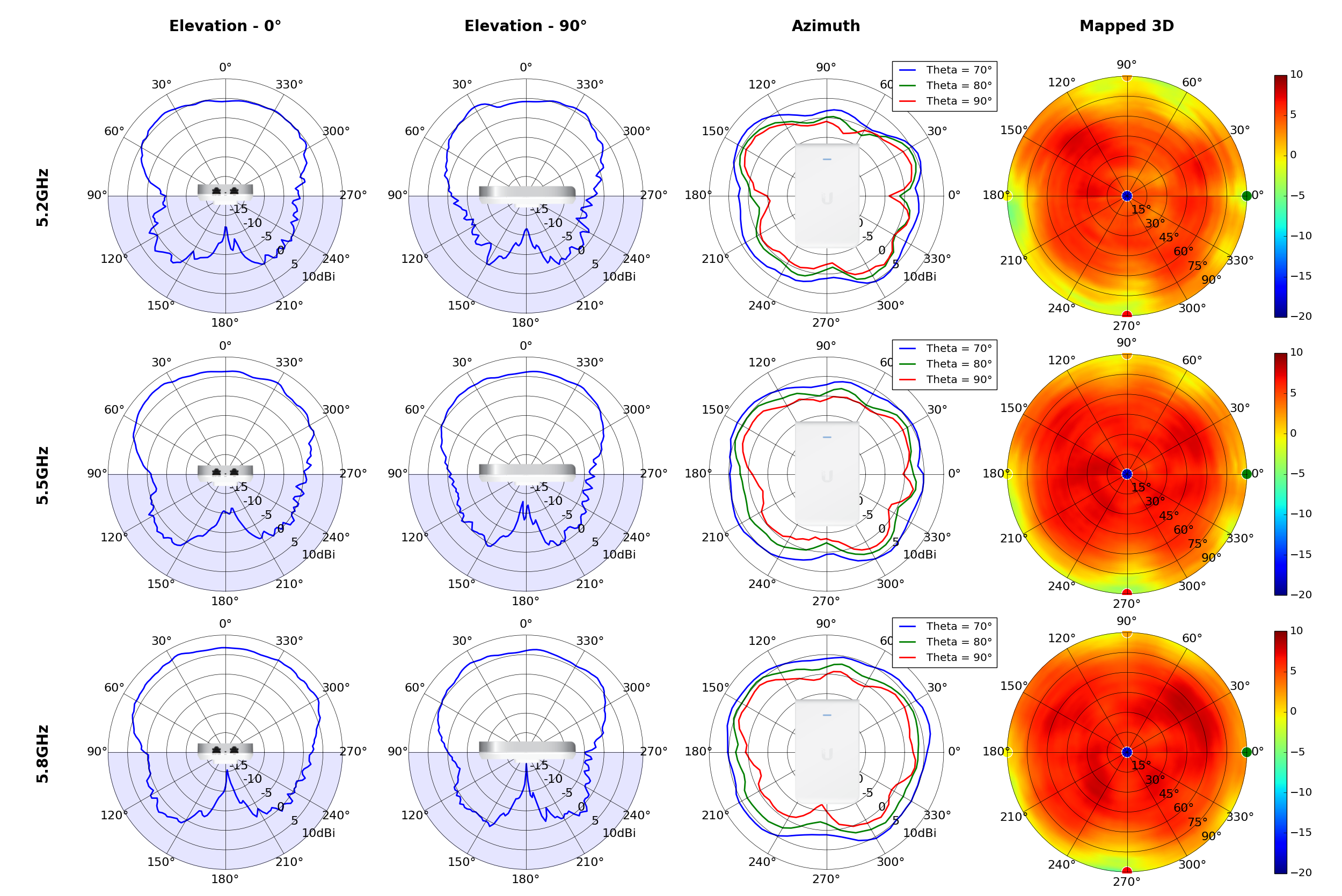
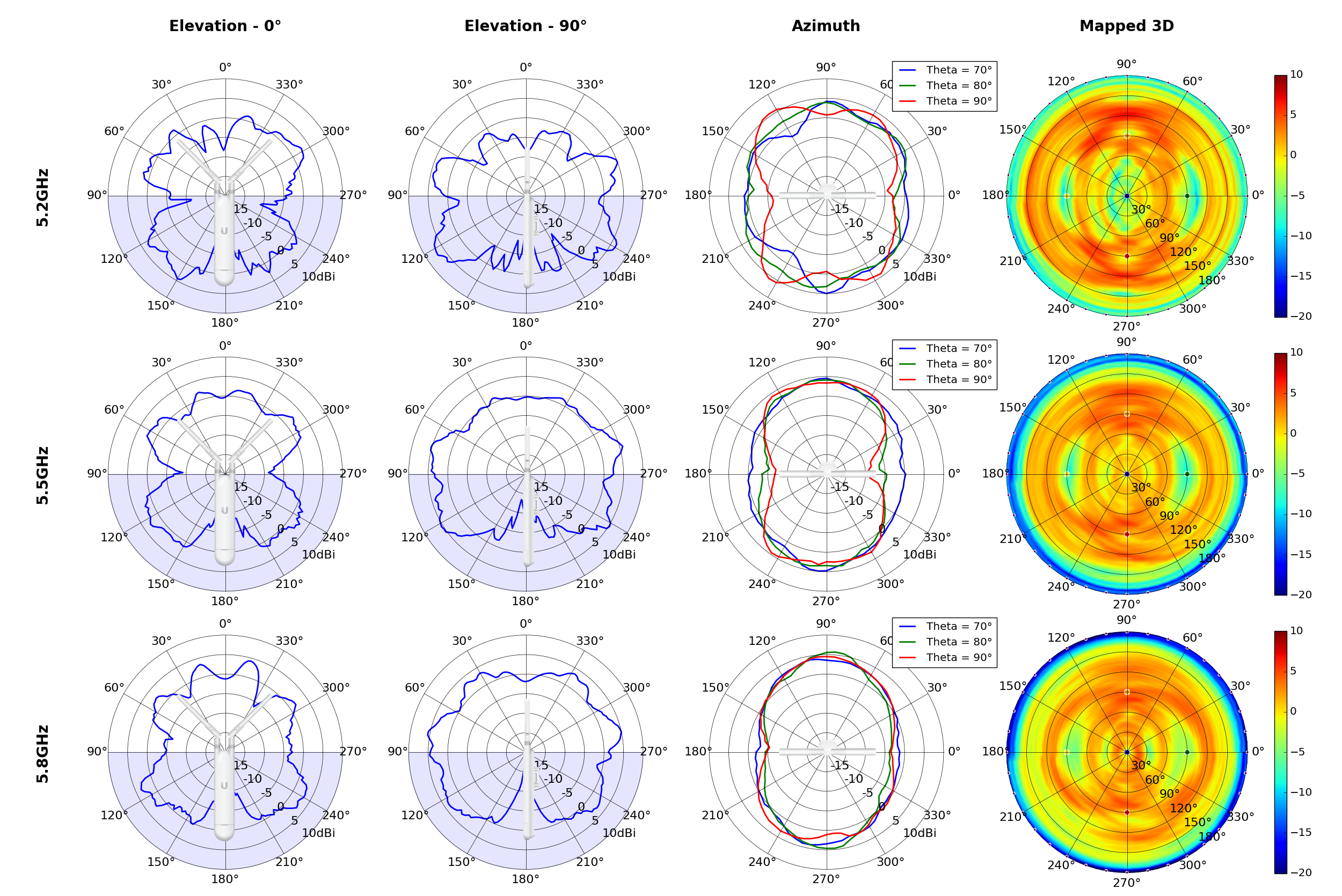
The Wi-Fi 6 Pro is the newer offering and comes with higher-gain antennae that go up to 6dBi, with maximum 5GHz throughput of 4.8Gbps, with the Long Range going up to 5.5dBi and 2.4Gbps over 5GHz. The Wi-Fi 6 Pro also is the only access point in Ubiquiti’s portfolio that offers the 160MHz channel.
I use a Wi-Fi 6 Long Range and Wi-Fi 6 Lite in my home, but if you’re starting from scratch, a good bet would be to get a Wi-Fi 6 Lite and Wi-Fi 6 Pro to get going and add more as needed. These access points seamlessly integrate into the UniFi network and can be configured with the UDM Pro.
UniFi Access Point Wi-Fi 6 Lite
The Wi-Fi 6 Lite access point has 2×2 MIMO and 1.2Gbps throughput over 5GHz, and it does a good job delivering reliable Wi-Fi 6 signal to all corners of your home.
UniFi Access Point Wi-Fi 6 Pro
Ubiquiti’s latest wireless access point has it all: 160MHz channels over Wi-Fi 6, 4×4 MIMO with a 4.8Gbps throughput at 5GHz, and the ability to connect to up to 300 clients.
Security camera and doorbell: G4 series
 Source: Ubiquiti
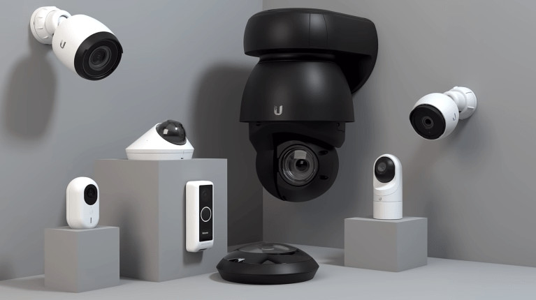
Security cameras are a big part of the UniFi Protect portfolio, and Ubiquiti offers a dozen products in this area. I use a combination of the G3 Flex, G4 Bullet, and the G4 Dome inside (and outside) my home, and they’re pretty good at what they do. Ubiquiti’s cameras draw power over PoE and let you record 1080p footage, plus you get weather resistance with the G4 series.
In my use case, I found the G3 Flex to be ideal as an indoor camera as it can be positioned just about anywhere inside the house, with the G4 Bullet and G4 Dome suited for outdoor use. The G3 Flex starts at $79, and you can pick up a pack of three for $229
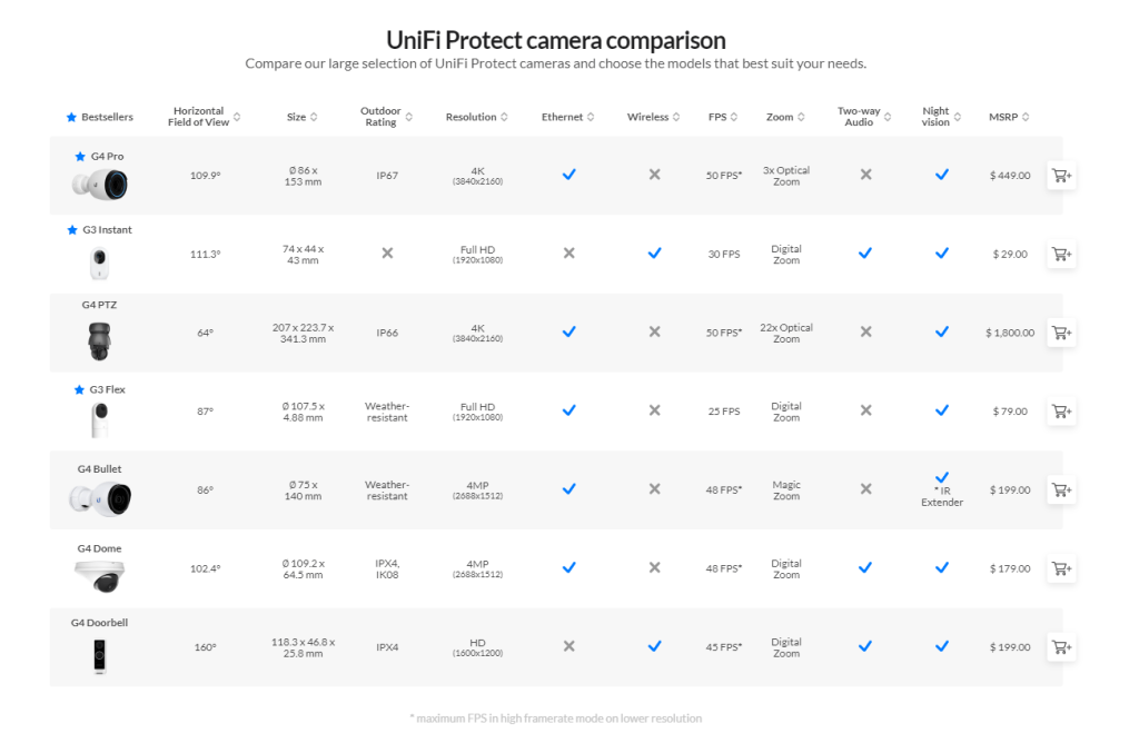
The G4 Bullet offers 1440p recording that sells for $199, and if you want 4K video, 3x zoom lens, and IP67, you will need to get the $449 G4 Pro. Several users had issues with condensation on the G4 Bullet last year, but that hasn’t been a drawback for me. I haven’t used Ubiquiti’s doorbells just yet. Still, the G4 Doorbell offers a similar set of features as other smart video doorbells, including two-way audio, motion detection, and Wi-Fi connectivity. Here’s a breakdown of the feature-set that each security camera offers:
 Source: Ubiquiti
You can pair the security cameras and doorbells to any UniFi routing solution with UniFi Protect. As for managing the security devices, you can install the UniFi Protect app on your phone and configure motion detection areas, privacy zones where the cameras won’t record footage, and smart detection for faces and vehicles.
You get a decent number of options for notifications, including the ability to set custom schedules and receive information at a set time. The cameras do a good job with motion detection and notification alerts, and UniFi Protect has a good UI that lets you view events and see recorded footage with ease. The best part is that all footage is stored locally, so you don’t have to pay a license fee to access all the features on offer. Unfortunately, there’s no active monitoring like you get with Arlo or Ring, but UniFi Protect gets a lot right for a self-hosted solution.
UniFi Camera G3 Flex
The G3 Flex is a great indoor camera, thanks to its versatile design. You get 1080p video recording, integrated IR LEDs for motion detection at night, and a built-in mic.
UniFi Camera G4 Bullet
The G4 Bullet has 1440p recording, a weather-sealed design, a built-in mic, a 110-degree angle of view, and LEDs for recording at night.
Building your UniFi network
 Source: Harish Jonnalagadda / Android Central
Ubiquiti has significantly expanded its consumer offerings in the last two years, and if you’re interested in getting started with an UniFi home network, you have a lot of choices. The UDM Pro is ideally suited as a routing solution because of the hardware on offer and the extensive feature-set and configuration. You can pair it with a multitude of switches and wireless access points.
The reason why I switched to UniFi was the extensibility. I started with the UDM Pro, Switch Pro 24 PoE, and the Wi-Fi 6 Long Range and Wi-Fi 6 Lite for wireless access. As for security cameras, I have three units of the G3 Flex for indoor use and a G4 Bullet located outside.
I’m now eyeing the Wi-Fi 6 Pro for the balcony as that’s the one area where I don’t get adequate coverage, and the G4 Doorbell as the video doorbell. I’ve deliberated getting a Nest Doorbell, but considering I have an UniFi Protect system set up anyway, I figured the G4 Doorbell would be a better alternative.
The biggest issue with Ubiquiti products is availability. The security cameras, in particular, are constantly sold out, so you will have to wait for a restock to get your hands on the G4 Bullet or even the Dream Router. Then you’ll need to factor in cabling as most of these devices connect over Ethernet. I’m fortunate that my home has internal Cat5 cabling, but you will need to consider that if you’re looking to make the switch.
The sheer amount of features in UniFi Network, the ease-of-use of UniFi Protect, and the fact that you have complete control over the recorded footage make Ubiquiti’s products an excellent choice for prosumers. Of course, building out the entire network is a sizeable investment if you’re picking up a UDM Pro, Switch 24 PoE, two APs, and a few security cameras, but at the end of the day, you get a scalable network that will serve you well for several years.
Source :
https://www.androidcentral.com/how-set-ultimate-ubiquiti-unifi-home-network-2022
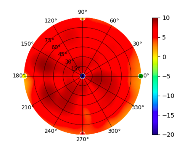
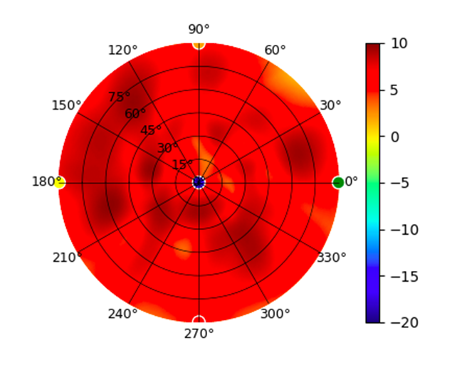
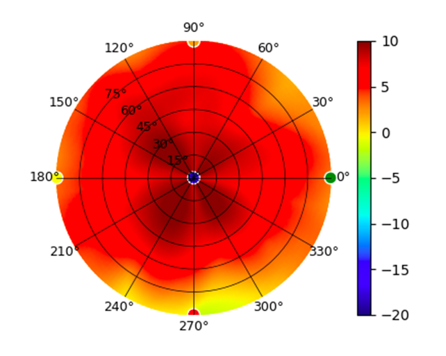
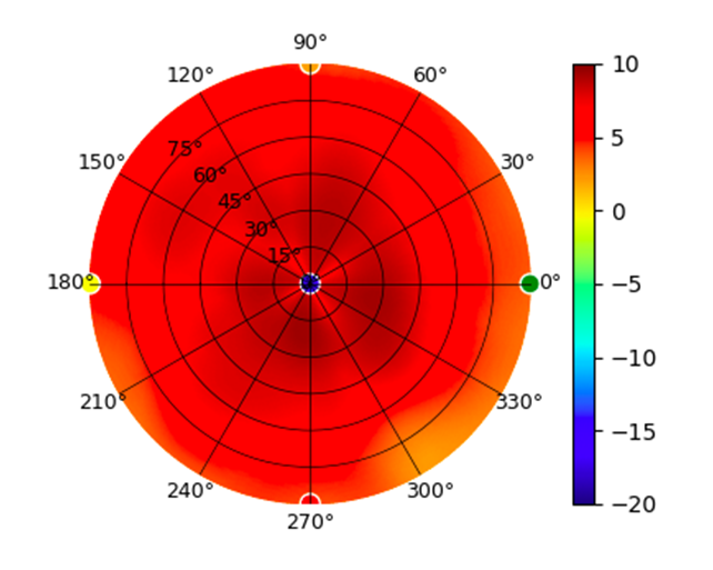
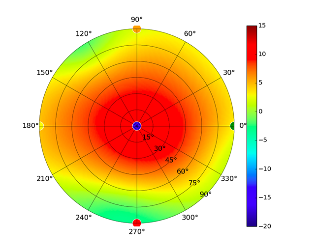
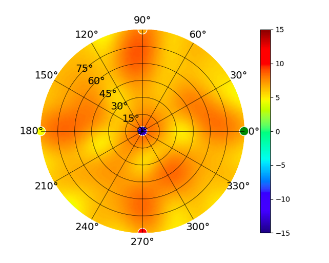
 (5.20GHz)
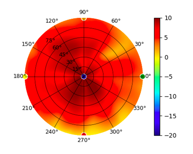
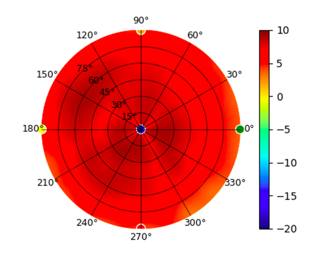
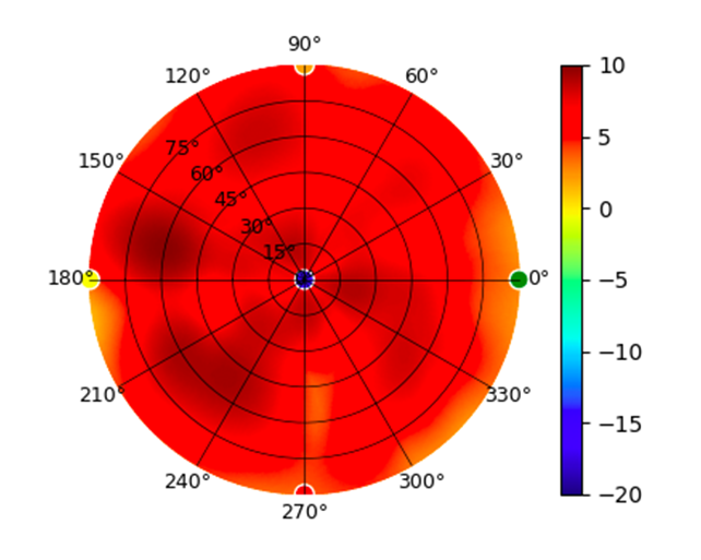
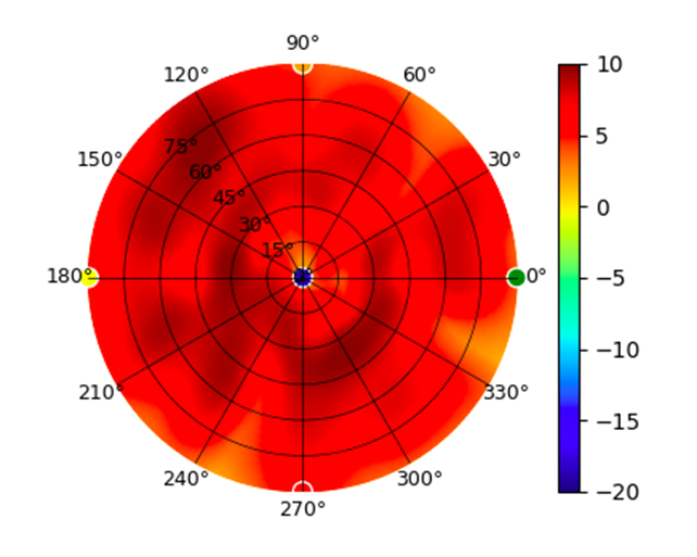
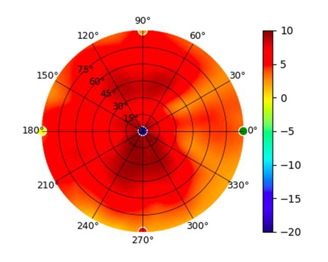
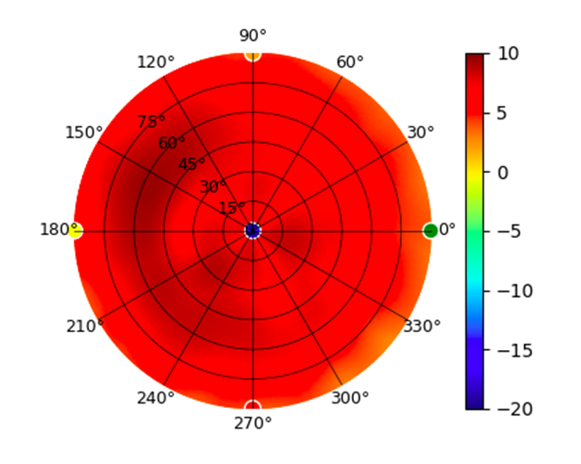
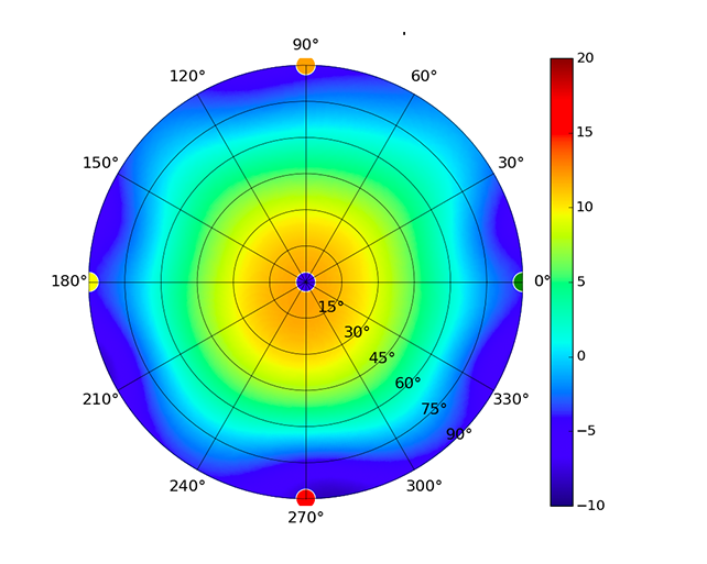
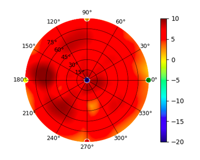
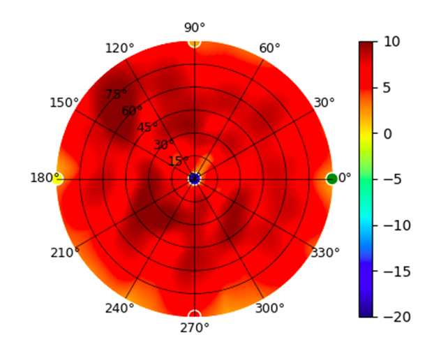
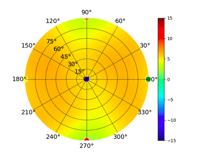
 (5.80GHz)
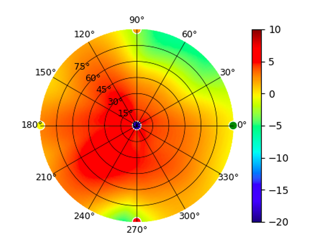
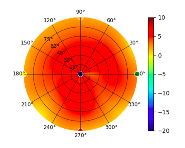
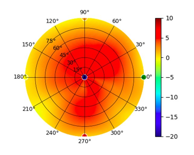
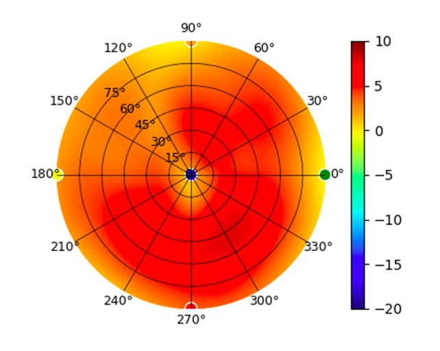
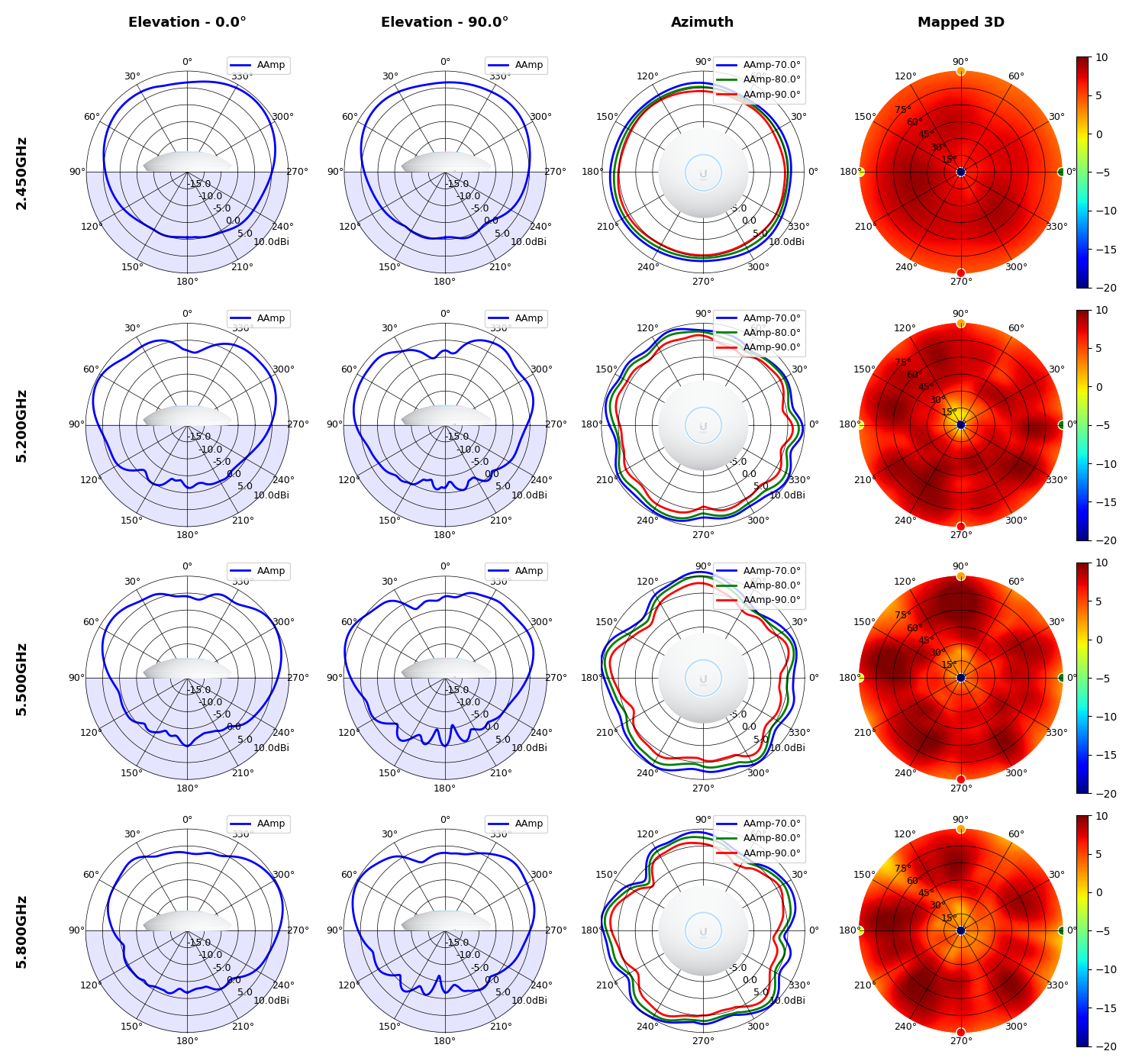
 (5.20GHz)
 (5.80GHz)
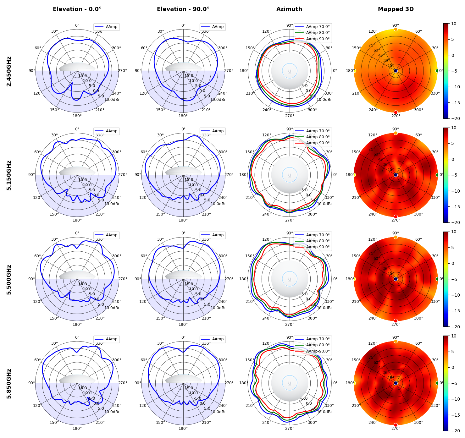
 (High Gain)
 (High Gain)
 (High Gain)