Launched in “early preview” in November 2021 the next version of System Center is going to be released in the first quarter of 2022.
In this article, we’ll look at what’s new in each of the main components, Virtual Machine Manager, Operations Manager and Data Protection Manager and make some predictions around the finished product.
Virtual Machine Manager 2022
If you have a medium to large deployment of Hyper-V clusters, VMM is a must for management. Somewhat equivalent to vCenter in the VMware world this is the server product that lets you manage templates for VMs, including templates with multiple VMs (called a service) and other artefacts as well as automated deployments. VMM also manages your Software Defined Networking (SDN) stack and your backend storage (SANs and S2D). Notably, it also manages VMware virtualization hosts and clusters and can also integrate with Azure for light VM management.

SC Virtual Machine Manager 2022 Installation
There are a few new features in this version but the running theme throughout System Center 2022 (unless there’s a surprise reveal at GA) is that this is mostly about finishing little details and ensuring compatibility with current platforms. VMM 2022 runs on Windows Server 2022 and can manage Windows Server 2022 hosts.
On the networking side, the SDN stack gets support for dual-stack IPv4 and IPv6. You’ll need to be using the SDN v2 stack but that’s been where any new features have appeared since System Center 2016. In case you’re not familiar, up to System Center 2012R2 / Windows Server 2012R2 Microsoft built their own network virtualization stack and protocol but in 2016 they offered VXLan from VMware as an alternative. They also switched to an Azure inspired architecture where there’s a set of Network Controller VMs running on your cluster, managing all the virtualized networks. There are also Software Load Balancer VMs managing incoming network traffic, plus a Gateway providing connectivity from a virtualized network to the wider world. The dual-stack support covers all of these components, including site to site VPN (IPSec, GRE tunnel and L3 tunnels) so if your datacenter is adopting IPv6 – VMM is all ready to go. Note that you’ll need to provide both IPv4 and IPv6 address pools when setting this up.

VMM Logical Network with IPv4 and IPv6 subnets
The other big-ticket item is support for Azure Stack HCI (version 20H2 and 21H2) and Windows Server 2022. Note that VMM 2019 Update Release 3 (UR3) does provide support for Azure Stack HCI 20H2. If you missed our Windows Server 2022 webinar and haven’t heard of Azure Stack HCI realize that it’s got very little to do with Azure. This is a special version of Windows Server and Hyper-V that you cluster on top of Storage Spaces Direct (S2D) which you can then manage from Azure. The benefit of Azure Stack HCI is that all the latest features in Windows Server (and Hyper-V) are released for it (unlike “normal” Windows Server) and the downside is that you pay a subscription fee per core, per month, for it.
You can add existing Azure Stack HCI clusters, and you can also create new ones from within VMM. You can manage the entire VM lifecycle, set up VLAN based networks, deploy/manage the SDN controller and manage storage, creation of virtual disks and cluster shared volumes (CSVs) and application of storage QoS. There are new PowerShell cmdlets to handle Azure Stack HCI (Register-SCAzStackHCI).
Note that disaggregated Azure Stack HCI clusters (for Scale Out File Server, SOFS) aren’t supported, nor is Live Migration from an Azure Stack HCI cluster to a Windows Server cluster (although quick migration should work).
I installed the “early preview” on a Windows Server 2022 VM, and it works as advertised, with no visual differences from VMM 2019.
Operations Manager
Apart from VMM, I think SCOM is probably the strongest part of System Center. This venerable product keeps an eye on everything in your virtualized datacenter. Using Dell/HP/Lenovo servers? Just install the free management pack and you’ll get hardware monitoring, down to individual fans in your servers. The same goes for your networking and storage gear. Properly configured, SCOM provides visibility into your entire datacenter stack, from physical hardware to user-facing application code.
There are two new RBAC roles: Read-only Administrator which does what it says on the tin, including reporting. The Delegated Administrator profile doesn’t include report viewing but you can customize exactly what it should be able to do by adding one or more of:
- Agent management
- Account management
- Connector Management
- Global settings
- Management pack authoring
- Notification management
- Operator permissions
- Reporting permissions
If you have disabled NTLM in your organization, SCOM 2016/2019 reporting services are impacted, 2022 has a new authentication type (Windows Negotiate) that fixes this issue.
An interesting twist is the ability to choose the alert closure behavior, in 2019 you can’t close an alert when the underlying monitor is unhealthy, now you can choose to be able to close the alert and reset the monitor health, which will let you bulk close alerts. This brings back the behavior from earlier versions of SCOM. Alternatively, you can choose to stay with the 2019 behavior.
There are improvements to the upgrade process where registry key settings and custom install location of the Monitoring Agent is maintained when going from SCOM 2019 to 2022.
Alerts can now be sent to Teams channels, instead of Skype for Business.
SCOM can also monitor Azure Stack HCI deployments, using a new MP, which is actually a grouping of current Management Packs (BaseOS, Cluster, Hyper-V, SDN and Storage).
There are also some other minor fixes such as running the SCOM database on SQL Always On (no post configuration changes required), SHA256 encryption for certificates for the Linux agent, the FQDN source of alerts is now shown when tuning Management Packs and you can view the alert source for active alerts. Newer Linux distros such as Ubuntu20, Debian 10 and Oracle Linux 8 are also now supported for monitoring.
The dependency on the LocalSystem account on Management Servers has been removed and just like the other System Center components, SCOM 2022 runs on Windows Server 2022.
Data Protection Manager
Apart from running on Windows Server 2022, there are a few improvements in DPM. The main one (depending on your restore scenarios) is removing the requirement of file catalogue metadata for individual file and folder restores and instead uses an iSCSI based approach which improves backup times and restores.
If you’re using DPM to protect VMware vCenter you can now restore VMs in parallel, the default value is up to 8 VM simultaneously but you can up that limit with a simple registry change. Speaking of vCenter, VMware 7.0, 6.7 and 6.5 are supported and you can now separate the VDDK logs that relate to VMware operations from the rest of the DPM logs and store them in a user-defined file.
Another “big” improvement is the change of the maximum data storage for a DPM server from 120 TB to 300 TB. As before, it’s recommended to have tiered storage with a small amount of SSD cache and the rest hard-drive-based and use the ReFS file system.
Should you be Excited?
It seems that System Center Orchestrator will come in a 64-bit version although the bits weren’t part of the Early Preview, nor were System Center Service Manager 2022.
Overall, for me there’s nothing that we’ve covered in this article that’s a “must-have” to entice me to upgrade but if I’m upgrading to Windows Server 2022 anyway, or considering Azure Stack HCI, it’s a natural step.
I often express it like this – System Center is on life support. Microsoft isn’t looking to gain more market share against other datacenter management suites, they’re simply keeping System Center up to date and able to manage the latest OSs so that if you’re already a customer – you have a comfortable upgrade path. All System Center products also incorporate various levels of Azure/Microsoft 365 integration to tick the box of being “hybrid” and helping enterprises in their journey to the cloud.
Source :
https://www.altaro.com/hyper-v/system-center-2022/


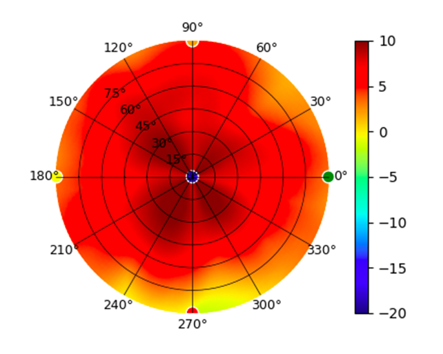
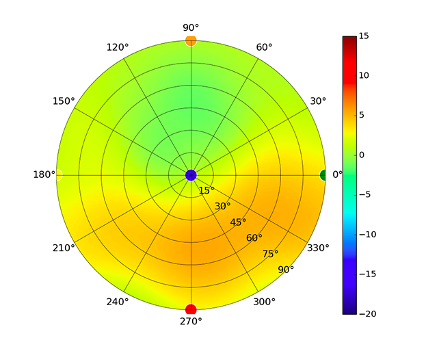
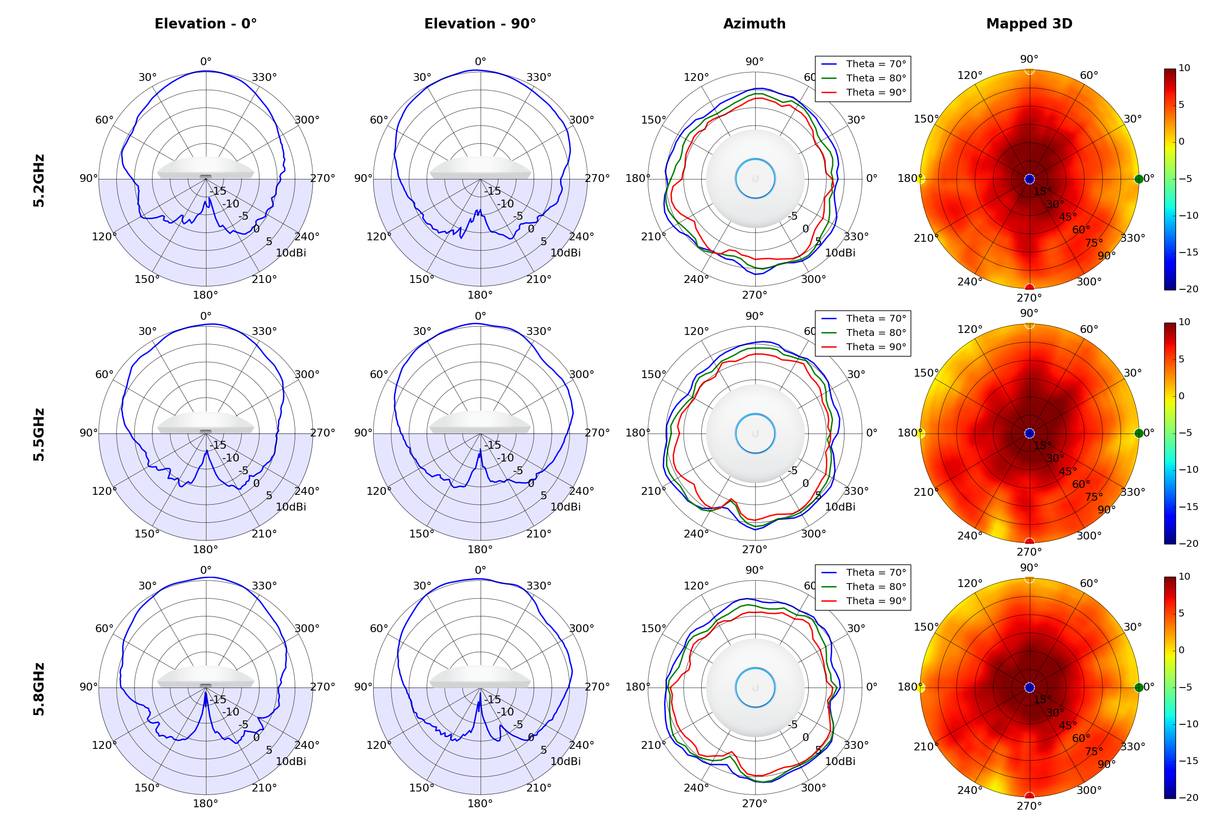
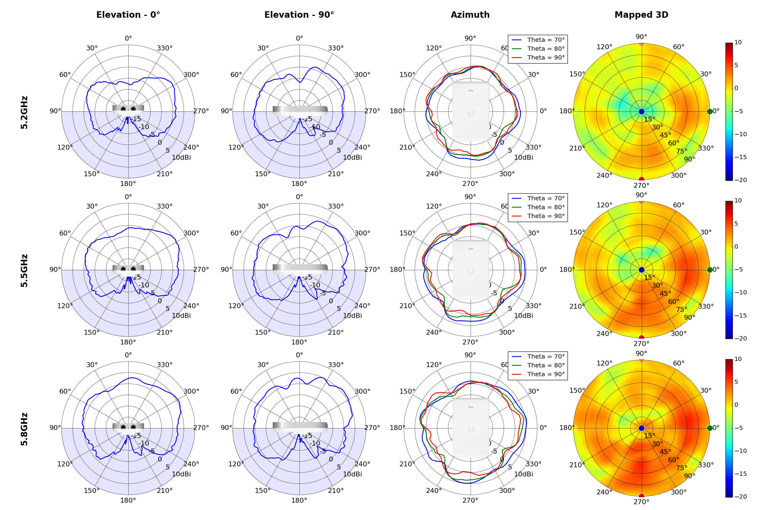
 (5.20GHz)
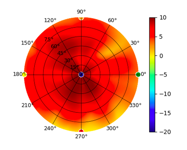
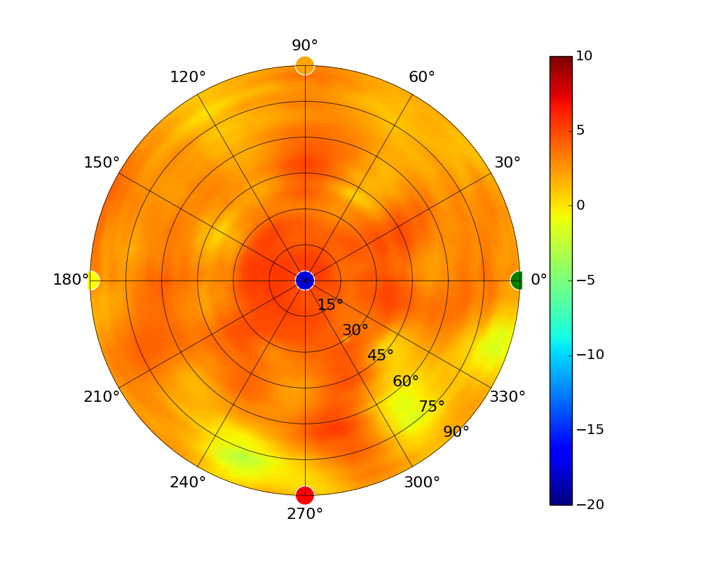
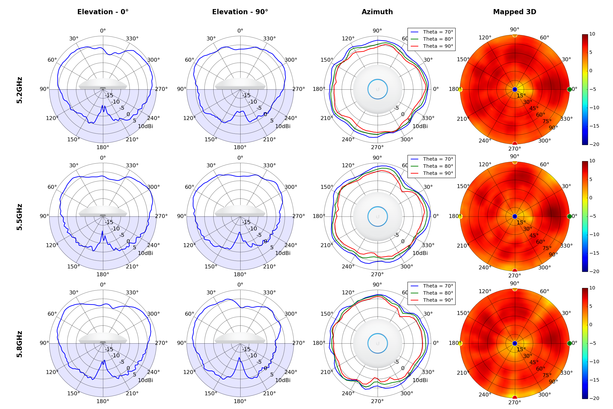
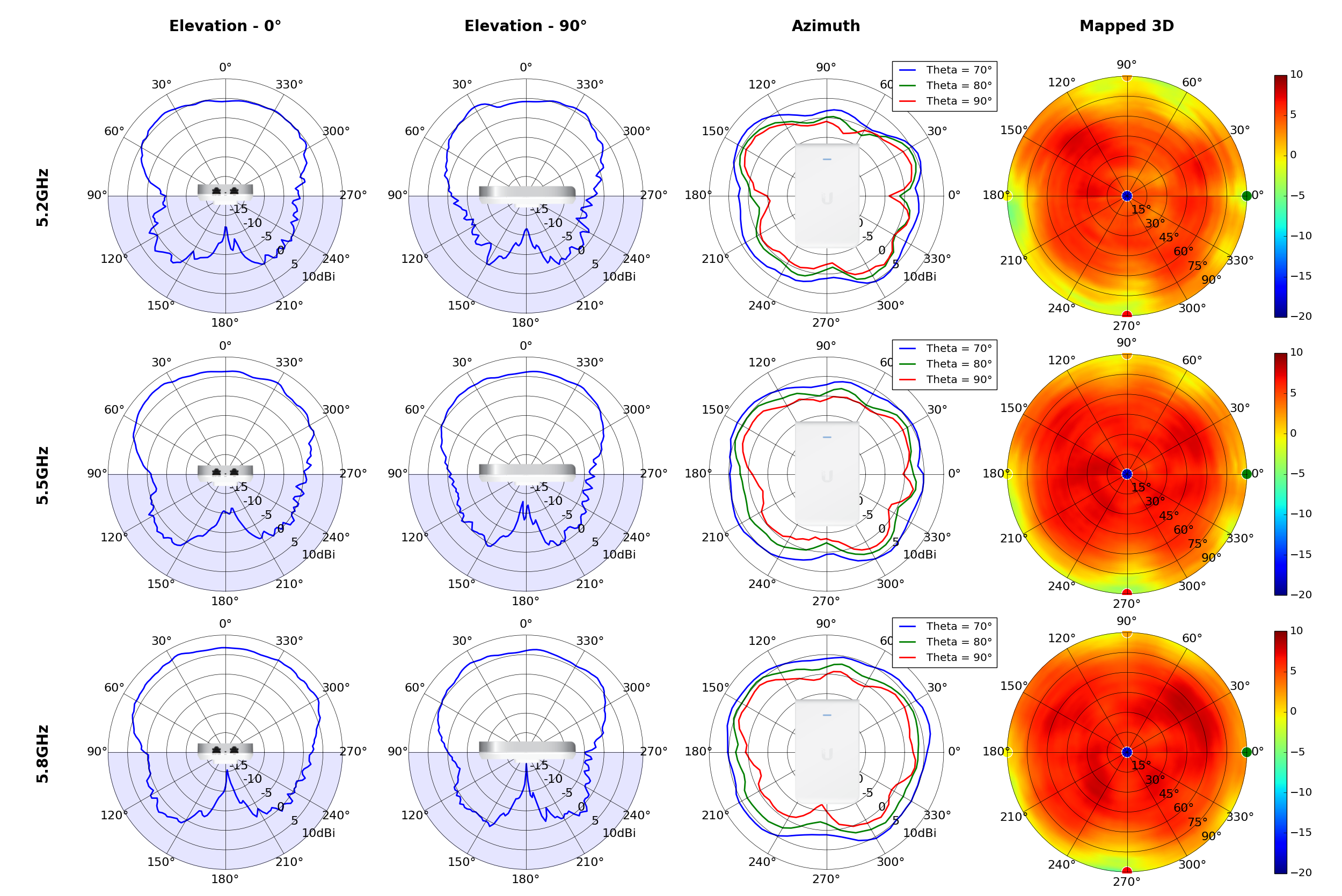
 (5.80GHz)

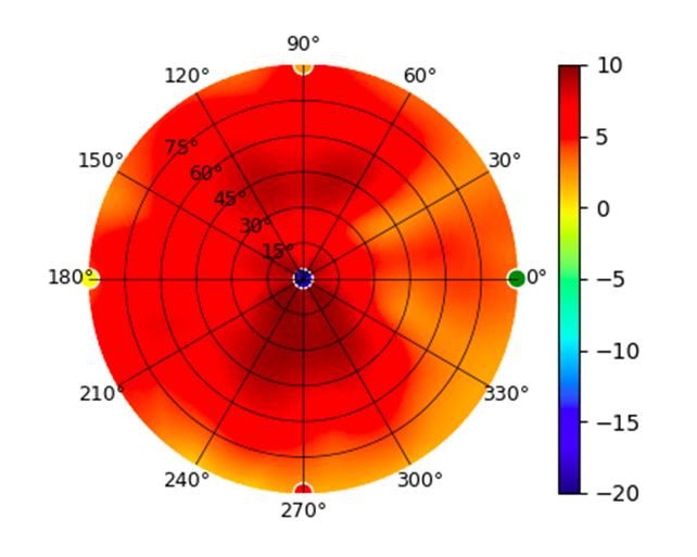
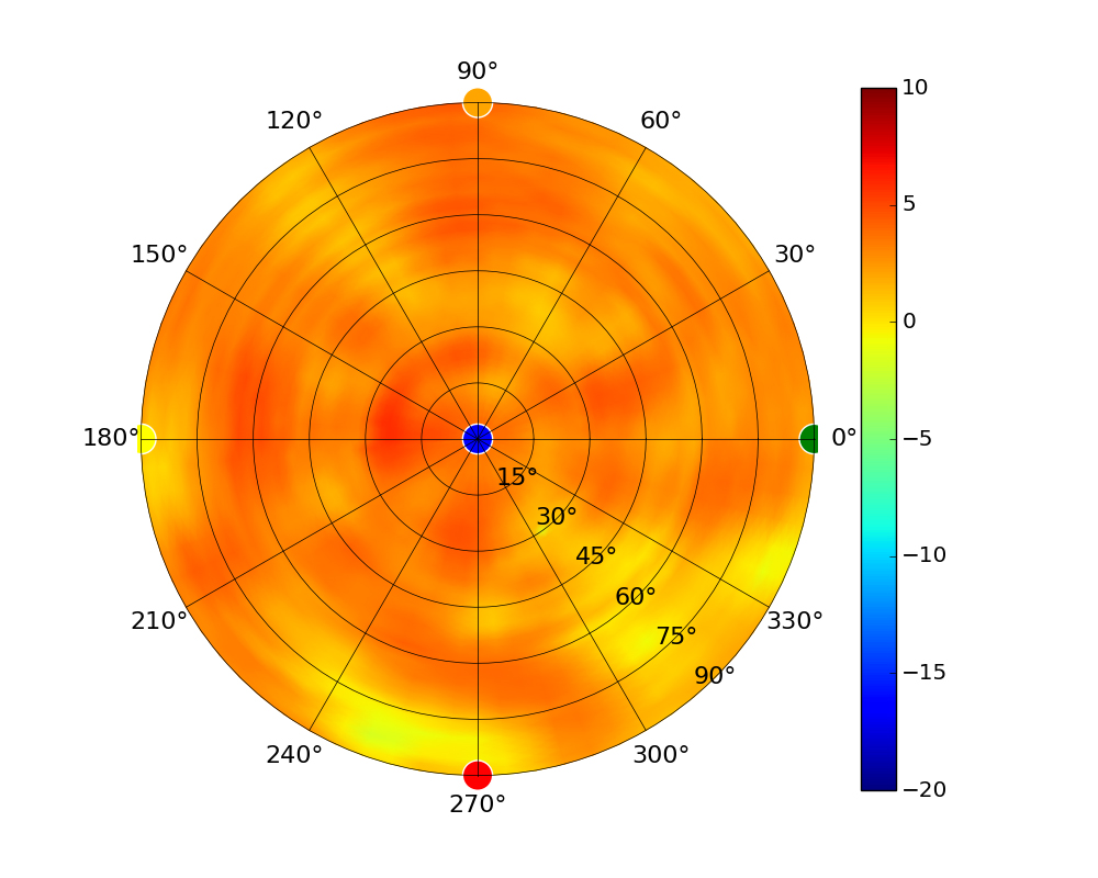
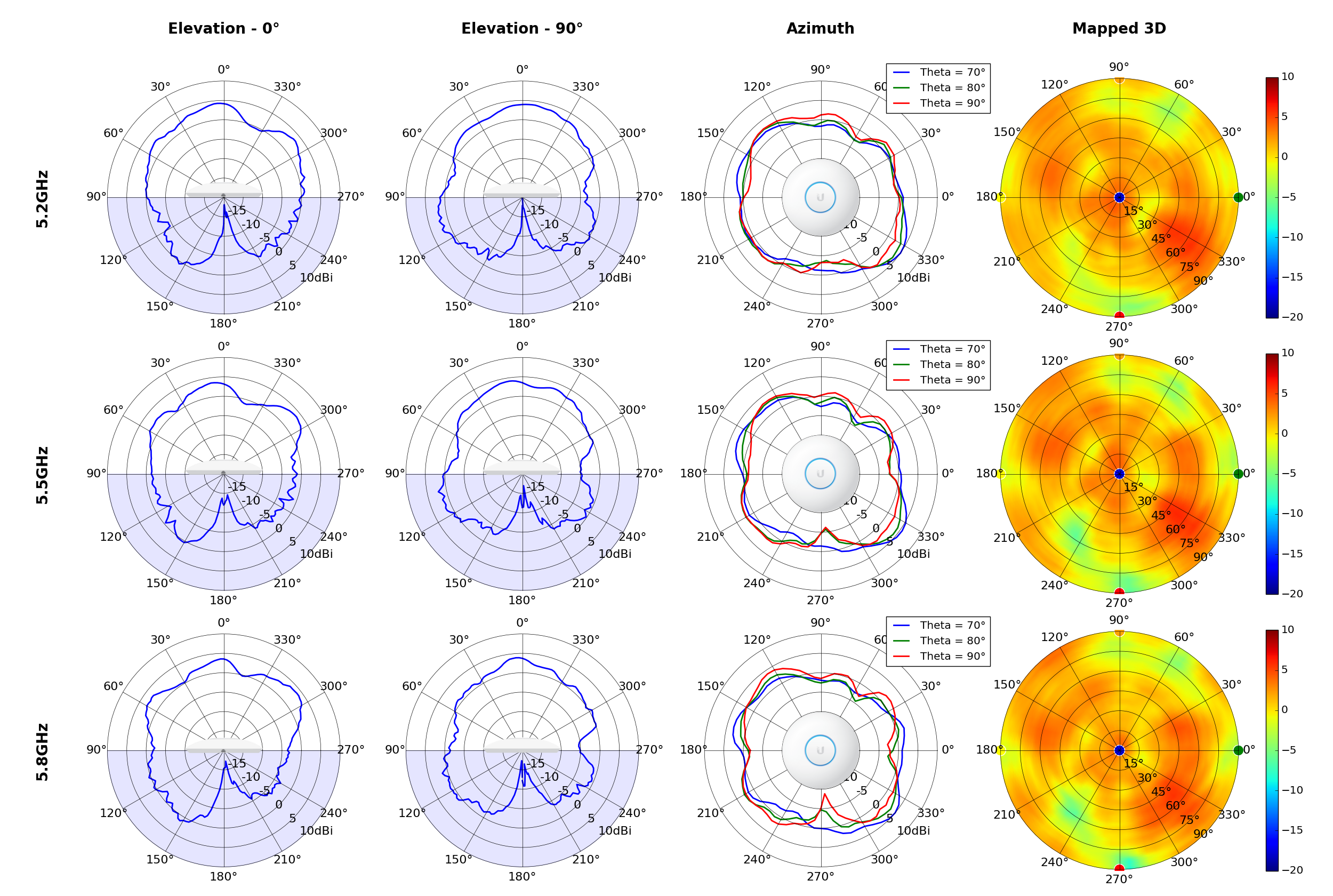
 (5.20GHz)
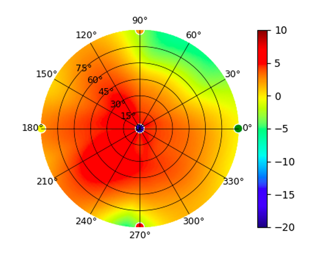
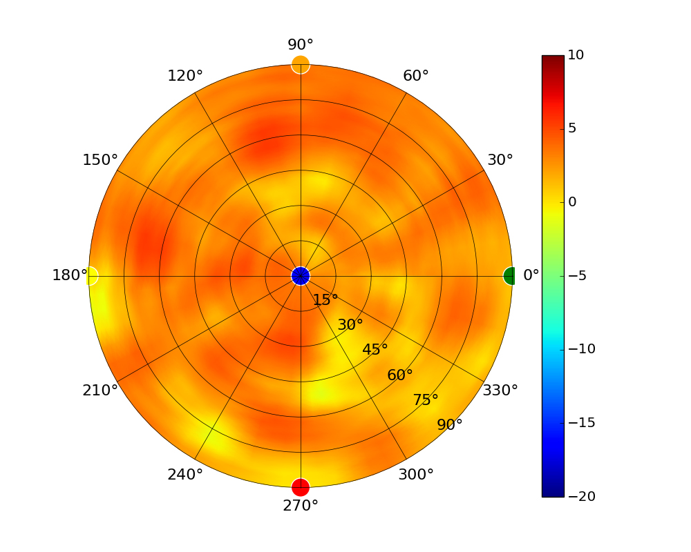
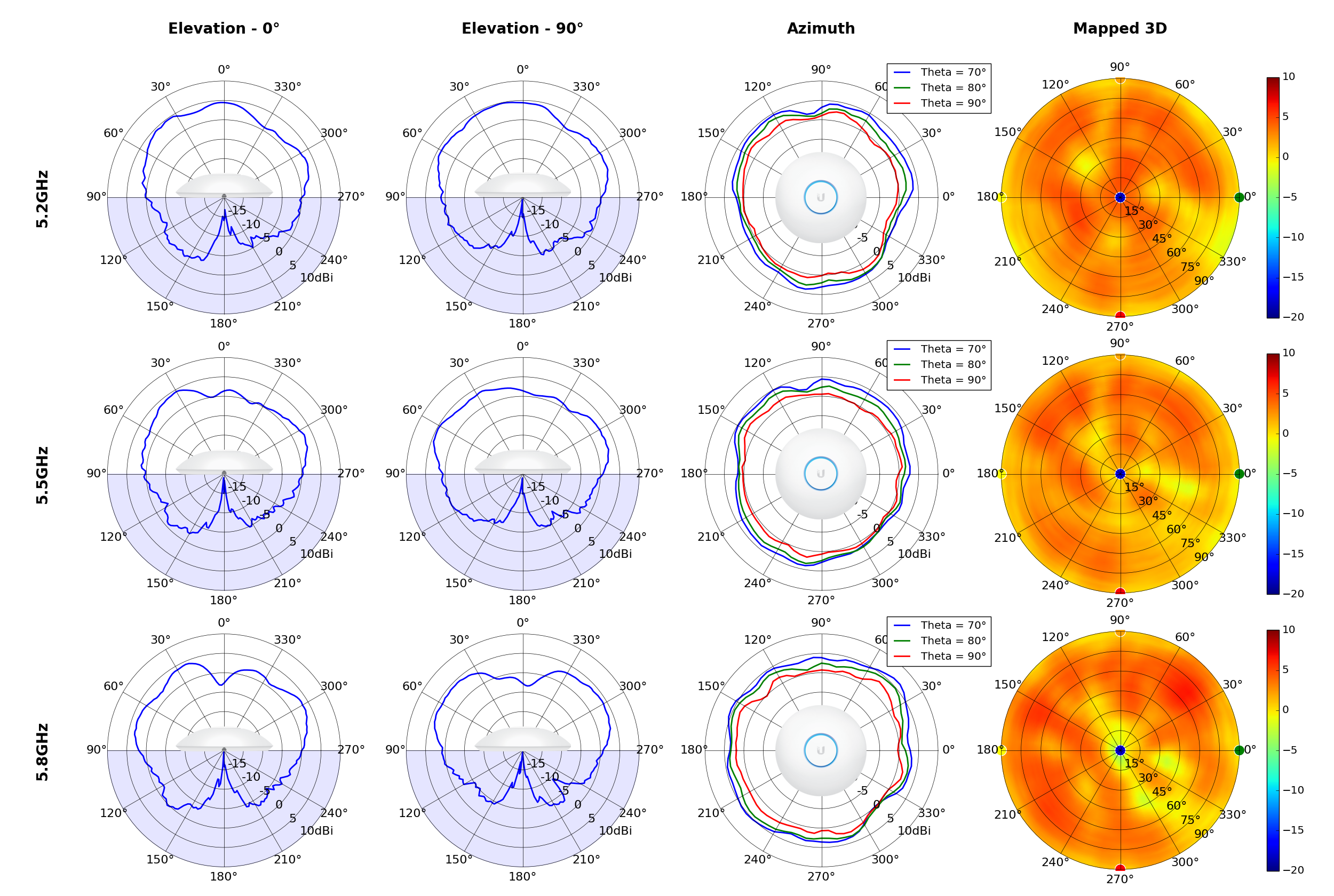
 (5.80GHz)
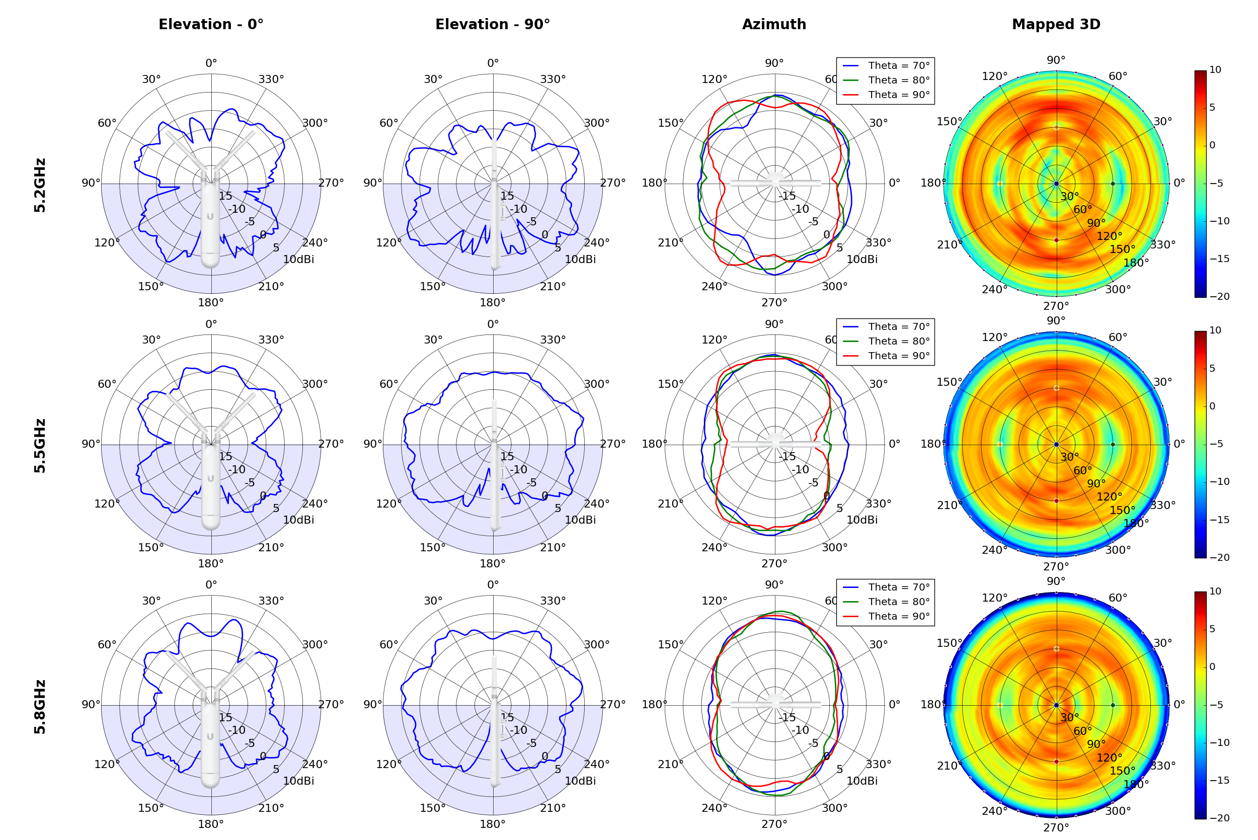
 (High Gain)
 (High Gain)
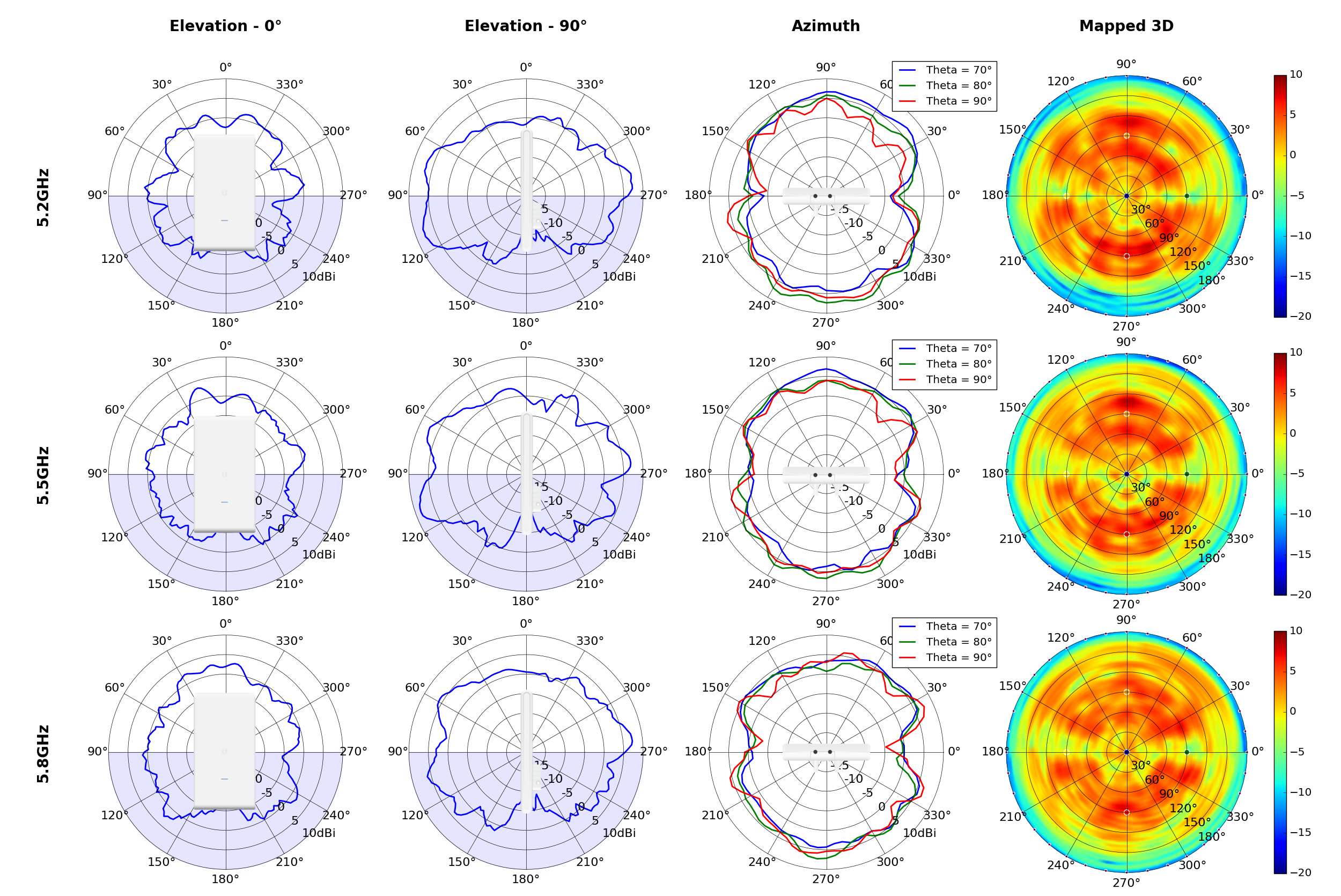
 (High Gain)