You can back up your important folders (your Desktop, Documents, and Pictures folders) on your Windows PC with OneDrive PC folder backup, so they’re protected and available on other devices. If you haven’t already set up OneDrive on your computer, see Sync files with OneDrive in Windows. There’s no extra cost for PC folder backup (up to 5 GB of files without a subscription). See OneDrive plans.
Note: If you’re surprised that your files are saving to OneDrive, see Files save to OneDrive by default in Windows 10.https://www.microsoft.com/en-us/videoplayer/embed/RE2PM4G?pid=ocpVideo0-innerdiv-oneplayer&jsapi=true&postJsllMsg=true&maskLevel=20&market=en-us
Set up PC folder backup
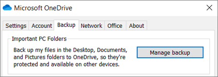
- If you’re prompted to back up your important folders (Desktop, Documents, and Pictures), select the prompt to start the folder backup wizard.If you didn’t see the prompt or you already closed the wizard, select the white or blue cloud icon in the Windows notification area, and then select Help & Settings > Settings, then Backup > Manage backup.
- In the Back up your folders dialog, make sure the folders that you want to back up are selected.
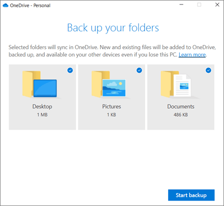
- Select Start backup.
- You can close the dialog box while your files sync to OneDrive. Or, to watch your files sync, select View upload progress. If you already closed the dialog, to open the OneDrive activity center, select the white or blue cloud in the notification area.
Access your backed up folders on any device
When your files finish syncing to OneDrive, they’re backed up and you can access them from anywhere in Documents, Desktop, or Pictures. When you back up your Desktop folder, the items on your desktop roam with you to your other PC desktops where you’re running OneDrive.
You can back up a maximum of 5 GB of files in OneDrive for free, or up to 1 TB with a Microsoft 365 subscription.
If you’re signed in to the OneDrive sync app on your computer, you can use File Explorer to access your OneDrive. You can also use the OneDrive mobile app to access your folders on any device.
Manage or stop PC folder backup
To stop or start backing up your folders in OneDrive, update your folder selections in OneDrive Settings.
- Open OneDrive settings (select the white or blue cloud icon in your notification area, and then select Help & Settings > Settings.)
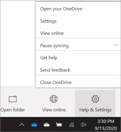
- In Settings, select Backup > Manage backup.
- To start backing up a folder, select any folder that doesn’t say Files backed up, and then select Start backup.
- To stop backing up a folder, select Stop backup, and confirm your request. See important notes below.
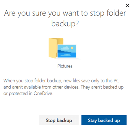
- When you stop backing up a folder, the files that were already backed up by OneDrive stay in the OneDrive folder, and will no longer appear in your device folder.
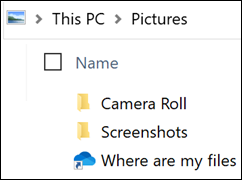
- In the folder that you stopped backing up, you’ll see an icon titled Where are my files that’s a shortcut to your folders in OneDrive. To access your files, select the icon to open the folder in OneDrive.
- If you want those files back in your device folder and not in OneDrive, move them manually from the OneDrive folder back to your device folder. Note that any new files you add to that folder on your device won’t be backed up by OneDrive after you stop the backup.
- To move the files. select Where are my files to open the folder in OneDrive, then select the files that you want to move to your device folder, and drag them to that location.
Fix problems with PC folder backup
Here are a list of errors you might see when you set up PC folder backup and how to resolve them:
- The following file type can’t be protected: Outlook database files (.pst).
- Folder protection is unavailable: A common reason for this error is that important folders on PCs that are connected to a domain can’t be protected in a personal OneDrive account (when you’re signed in with a Microsoft account). For info about data protection solutions, contact your IT administrator. You shouldn’t have this issue with a work or school account.
- File exceeds the maximum path length: Make sure the entire file path, including the file name, contains fewer than 260 characters. An example of a file path is:
C:\Users\<UserName>\Pictures\Saved\2017\December\Holiday\NewYears\Family…
To resolve this, shorten the name of your file or the name of subfolders in OneDrive, or select a sub-folder that’s closer to the top-level folder. - File exceeds the maximum file size: OneDrive can’t sync files over 250GB. Remove these files from the folder you want to protect and then try again.
- The file name isn’t allowed in OneDrive: File names can’t start with a space or include any of these characters: \ : / * ? < > ” |. Please move or rename the file to continue.
- The folder isn’t selected for syncing: The folder with the error is not syncing to your PC. To resolve this error, open OneDrive Settings (right-click the white or blue cloud icon in your notification area, and select Settings), select Choose Folders, and then make sure the folder you want to protect is selected. If Pictures is showing this error, make sure that Pictures, Screenshots, and Camera Roll are all selected (or don’t exist). It’s also possible that the OneDrive folder has a different name from the Windows important folder.
- Important folders aren’t in the default locations: The folder with the error contains another important folder and can’t be protected until the contained folder is moved. Important folders that may be contained within the folder include: Documents, Desktop, Pictures, Screenshots, Camera Roll, or the OneDrive folder.
- An unknown error occurred, with error code 0x80070005: If you receive error code 0x80070005, the “Prohibit User from manually redirecting Profile Folders” group policy is enabled. You may find that the files from the folders you selected were moved to identically named folders in your OneDrive folder, and the original locations are empty. Move the folder contents back to the original locations and ask your administrator whether the policy can be changed.
- Folder contains a reparse point (junction point or symlink): The folder you want to protect contains a special file type that links parts of the file system together. These items can’t be protected. To protect the folder, remove the file causing the issue.
- Post PC folder backup: OneDrive tries to automatically re-open notebooks that were previously open. In rare cases, some notebooks may not be automatically loaded in the OneNote desktop app after PC folder backup. Workaround for this issue is to reopen the notebooks in the OneNote app using File > Open.Caution: Some applications may depend on these links to function properly. Remove only the links that you know are safe to modify.
Source :
https://support.microsoft.com/en-us/office/back-up-your-documents-pictures-and-desktop-folders-with-onedrive-d61a7930-a6fb-4b95-b28a-6552e77c3057
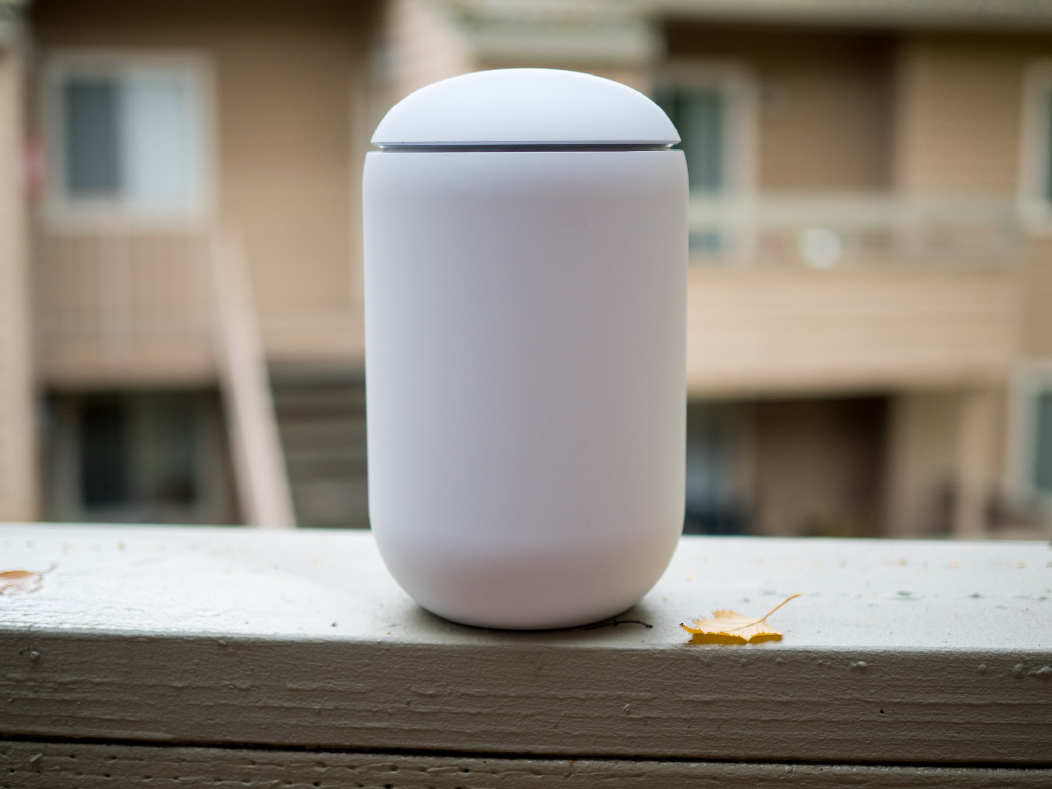 Source: Harish Jonnalagadda / Android Central
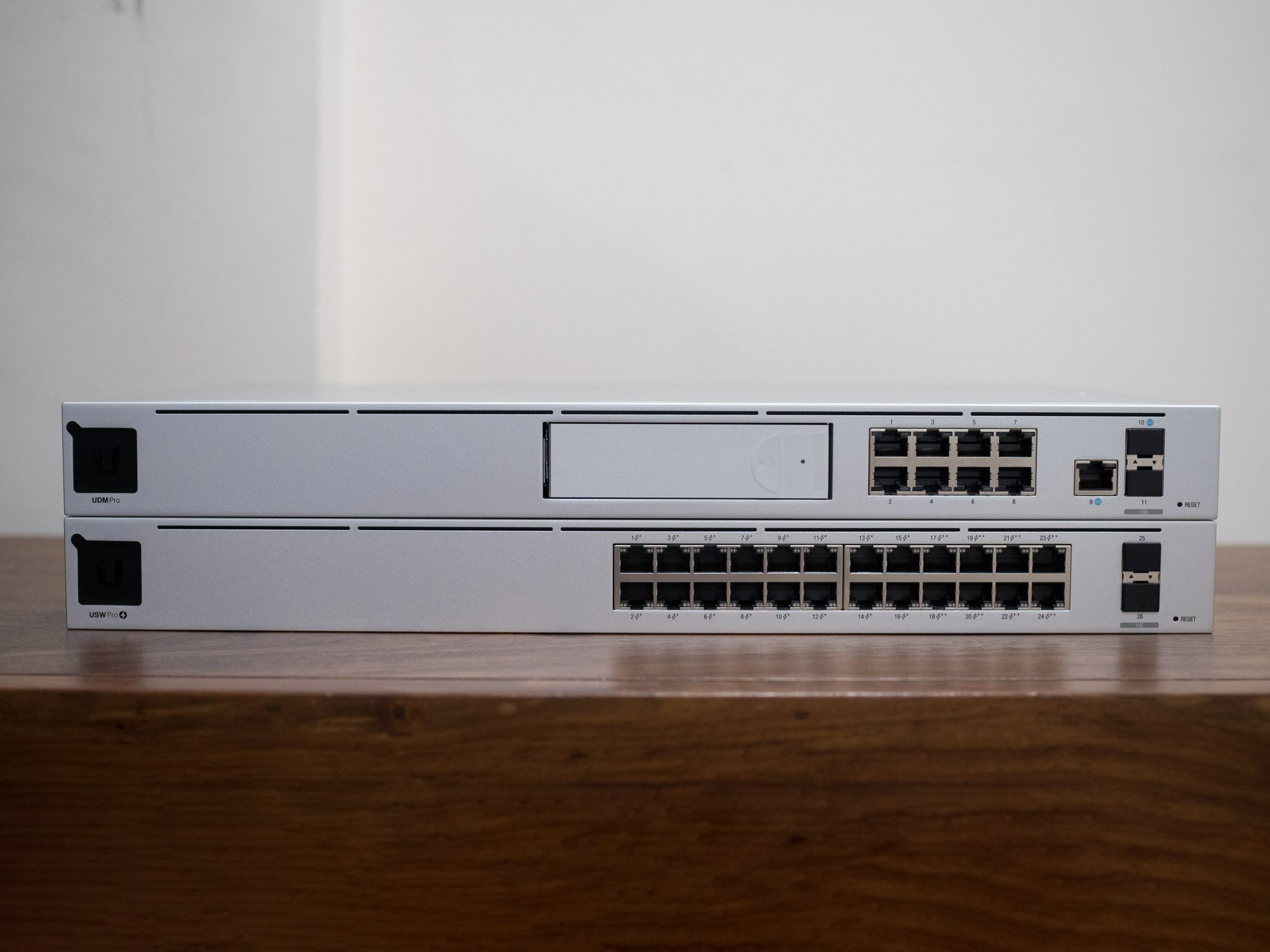 Source: Harish Jonnalagadda / Android Central
 Source: Harish Jonnalagadda / Android Central
 Source: Ubiquiti
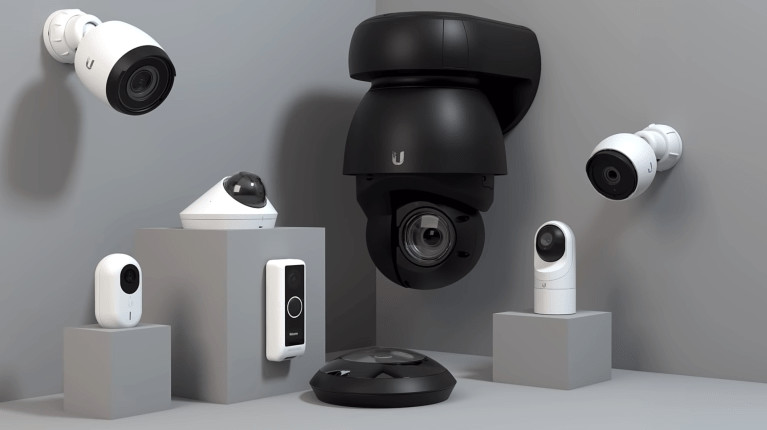 Source: Ubiquiti
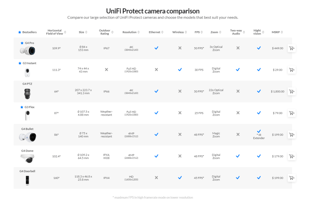 Source: Ubiquiti
 Source: Harish Jonnalagadda / Android Central