Contemporary organizations understand the importance of data and its impact on improving interactions with customers, offering quality products or services, and building loyalty.
Data is fundamental to business success. It allows companies to make the right decisions at the right time and deliver the high-quality, personalized products and services that customers expect.
There is a challenge, though.
Businesses are collecting more data than ever before, and new technologies have accelerated this process dramatically. As a result, organizations have significant volumes of data, making it hard to manage, protect, and get value from it.
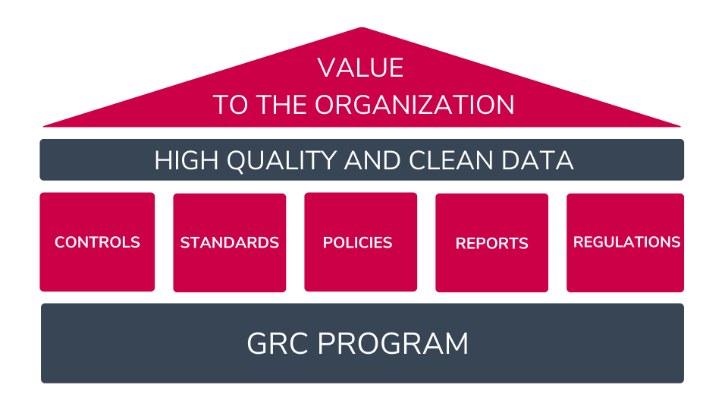
Here is where Governance, Risk, and Compliance (GRC) comes in. GRC enables companies to define and implement the best practices, procedures, and governance to ensure the data is clean, safe, and reliable across the board.
More importantly, organizations can use GRC platforms like StandardFusion to create an organizational culture around security. The objective is to encourage everyone to understand how their actions affect the business’s success.
Now, the big question is:
Are organizations getting value from their data?
To answer that, first, it’s important to understand the following two concepts.
Data quality
Data quality represents how reliable the information serves an organization’s specific needs — mainly supporting decision-making.
Some of these needs might be:
- Operations – Where and how can we be more efficient?
- Resource distribution – Do we have any excess? Where? And why?
- Planning – How likely is this scenario to occur? What can we do about it?
- Management – What methods are working? What processes need improvement?
From a GRC standpoint, companies can achieve data quality by creating rules and policies so the entire organization can use that data in the same ways. These policies could, for example, define how to label, transfer, process, and maintain information.
Data Integrity
Data integrity focuses on the trustworthiness of the information in terms of its physical and logical validity. Some of the key characteristics to ensure the usability of data are:
- Consistency
- Accuracy
- Validity
- Truthfulness
GRC’s goal for data integrity is to keep the information reliable by eliminating unwanted changes between updates or modifications. It is all about the data’s accuracy, availability, and trust.
How GRC empowers organizations achieve high-quality data
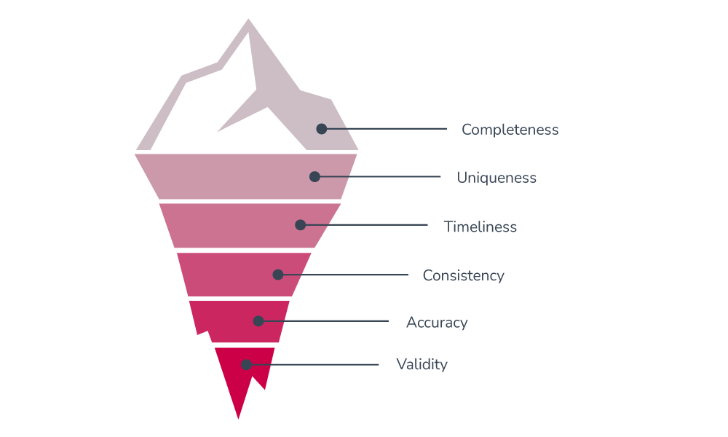
Organizations that want to leverage their data to generate value must ensure the information they collect is helpful and truthful. The following are the key characteristics of high-quality data:
- Completeness: The expected data to make decisions is present.
- Uniqueness: There is no duplication of data.
- Timeliness: The data is up-to-date and available to use when needed.
- Validity: The information has the proper format and matches the requirements.
- Accuracy: The data describes the object correctly in a real-world context.
- Consistency: The data must be the same across multiple databases
A powerful way to make sure the company’s data maintains these six characteristics is by leveraging the power of GRC.
Why?
Because GRC empowers organizations to set standards, regulations, and security controls to avoid mistakes, standardize tasks and guide personnel when collecting and dealing with vital information.
GRC helps organizations answer the following questions:
- How is the company ensuring that data is available for internal decision and for the clients?
- Is everyone taking the proper steps to collect and process data?
- Have redundancies been removed?
- Is the organization prepared for unexpected events?
- Does the organization have a backup system?
- Are the key processes standardized?
Overall, GRC aims to build shared attitudes and actions towards security.
Why every organization needs high-quality data and how GRC helps
Unless the data companies collect is high-quality and trustworthy, there’s no value in it — it becomes a liability and a risk for the organization.
Modern companies recognize data as an essential asset that impacts their bottom line. Furthermore, they understand that poor data quality can damage credibility, reduce sales, and minimize growth.
In today’s world, organizations are aiming to be data-driven. However, becoming a data-driven organization is tough without a GRC program.
How so?
Governance, Risk, and Compliance enable organizations to protect and manage data quality by creating standardized, controlled, and repeatable processes. This is key because every piece of data an organization process has an associated risk.
By understanding these risks, companies can implement the necessary controls and policies for handling and extracting data correctly so that every department can access the same quality information.
Organizations without structured data can’t provide any value, and they face the following risks:
- Missed opportunities: Many leads are lost because of incomplete or inaccurate data. Also, incorrect data means wrong insights, resulting in missing critical business opportunities.
- Lost revenue: According to 2021 Gartner’s research, the average financial impact of poor data quality on organizations is $12.9 million annually.
- Poor customer experience: When data quality is poor, organizations can’t identify customers’ pain points and preferences. As a result, the offer of products or services doesn’t match customers’ needs and expectations.
- Lack of compliance: In some industries where regulations control relationships or customer transactions, maintaining good-quality data can be the difference between compliance and fines of millions of dollars. GRC is vital to keep compliance in the loop as new regulations evolve worldwide.
- Increased expenses: A few years ago, IBM’s research showed that businesses lost 3.1 trillion dollars in the US alone. How? Spending time to find the correct data, fixing errors, and just hunting for information and confirmed sources.
- Misanalysis: Around 84% of CEOs are concerned about the quality of data they are deciding on. Wrong data will lead to bad decisions and ultimately damage operations, finances, HR, and every area within the company.
- Reputational damage: In today’s world, customers spend a lot of their time reading reviews before making a decision. For instance, if a company fails to satisfy its customers, everyone will know.
- Reduced efficiency: Poor data quality forces employees to do manual data quality checks, losing time and money.
To sum up:
Having the right processes to manipulate data will prevent organizations from missing business opportunities, damaging their reputation, and doing unnecessary repetitive tasks.
How GRC supports data-driven business and what are the key benefits of clean data
Data-driven businesses embrace the use of data (and its analysis) to get insights that can improve the organization. The efficient management of big data through GRC tools helps identify new business opportunities, strengthen customer experiences, grow sales, improve operations, and more.
For example, GRC helps data-driven businesses by allowing them to create and manage the right policies to process and protect the company’s data.
More importantly, organizations can also control individual policies to ensure they have been distributed and acknowledged accordingly.
In terms of benefits, although clean data has numerous “easy-to-identify” benefits, many others are not easily identified. Trusting data not just improves efficiency and results; it also helps with fundamental, vital factors that affect business performance and success.
What are these factors?
Fundamental benefits:
- Profits/Revenue
- Internal communication
- Employees confidence to share information
- Company’s reputation
- Trust
Operational benefits:
- Efficiency
- Business outcome
- Privacy issues
- Customer satisfaction
- Better audience-targeting
How GRC protect the value of businesses and their data
In this contemporary world, companies should be measured not only via existing financial measurements but also by the amount of monetizable data they can capture, consume, store and use. More importantly, how the data helps the organization’s internal processes to be faster and more agile.
When people think of high-quality data and big data, they usually associate these two with big organizations, especially technology and social media platforms. However, big quality data gives organizations of any size plenty of benefits.
Data quality and integrity help organizations to:
- Understand their clients
- Enhance business operations
- Understand industry best practices
- Identify the best partnership options
- Strengthen business culture
- Deliver better results
- Make more money
Using the right GRC platform helps companies create and control the policies and practices to ensure their data is valid, consistent, accurate, and complete — allowing them to get all these benefits.
The key to using GRC tools is that businesses can produce what customers expect on a greater scale and with higher precision and velocity.
Now, what does this have to do with value?
By protecting the value of data, organizations are protecting their overall worth. Indeed, GRC empowers companies to create a culture of value, giving everyone education and agency so they can make better decisions.
Also, GRC helps companies tell better security stories. These stories aim to build trust with customers and partners, enter new markets, and shorten sale cycles.
To summarize:
A better understanding of customers and processes — through data — will lead to better products and services, enhanced experiences, and long-lasting relationships with customers. All these represent growth and more revenue for companies.
What happens when a company’s data is not safe? Can it damage their value?
Trust is a vital component of any interaction (business or personal) and, as such, is mandatory for organizations to protect it — without trust, there is no business.
When data is not protected, the chances of breaches are higher, causing direct and indirect costs.
Direct costs are:
- Fines
- Lawsuits
- Stolen information
- Compensations
- Potential business loss
Indirect costs are:
- Reputation/Trust
- PR activities
- Lost revenue from downtime
- New and better protection
Often, reputation damages can cause long-term harm to organizations, making it hard for them to acquire and maintain business. In fact, reputation loss is the company’s biggest worry, followed by financial costs, system damage, and downtime.
So, what does all this mean?
It’s not just about collecting data; it is also about how companies reduce risks and leverage and protect the data they have. GRC integrates data security, helping organizations be better prepared against unauthorized access, corruption, or theft.
Moreover, GRC tools can help elevate data security by controlling policies, regulations, and predictable issues within the organization.
The bottom line?
When companies can’t get or maintain customers because of a lack of trust, the organization’s value will be significantly lower — or even zero. Unfortunately, this is even more true for small and medium size companies.
How to use GRC to achieve and maintain high-quality data?
Many organizations have trouble managing their data, which, unfortunately, leads to poor decisions and a lack of trust from employees and customers.
Moreover, although companies know how costly wrong information is, many are not working on ensuring quality data through the right processes and controls. In fact, Harward Business Review said that 47% of newly created data records have at least one critical error.
Why is that?
Because there is a lack of focus on the right processes and systems that need to be in place to ensure quality data.
What do poor processes cause?
- Human errors
- Wrong data handling
- Inaccurate formatting
- Different sets of data for various departments
- Unawareness of risks
- Incorrect data input or extraction
Fortunately, GRC’s primary goal is to develop the right policies and procedures to ensure everyone in the organization appropriately manages the data.
GRC aims to create a data structure based on the proper governance that will dictate how people organize and handle the company’s information. As a result, GRC will empower companies to be able to extract value from their data.
That is not everything.
Governance, Risk, and Compliance allow organizations to understand the risks associated with data handling and guide managers to create and distribute the policies that will support any data-related activity.
The following are some of the ways GRC is used to achieve and maintain high-quality data:
- Data governance: Data governance is more than setting rules and telling people what to do. Instead, it is a collection of processes, roles, policies, standards, and metrics that will lead to a cultural change to ensure effective management of information throughout the organization.
- Education: Achieving good data quality is not easy. It requires a deep understanding of data quality principles, processes, and technologies. GRC facilitates the education process by allowing the organization to seamlessly implement, share, and communicate its policies and standards to every department.
- Everyone is involved: Everyone must understand the organization’s goal for data quality and the different processes and approaches that will be implemented. GRC focuses on cultural change.
- Be aware of threats: When managing data, each process has risks associated with it. The mission of GRC is for the organization to recognize and deal with potential threats effectively. When companies are aware of risks, they can implement the necessary controls and rules to protect the data.
- One single source of truth: A single source of truth ensures everyone in the organization makes decisions based on the same consistent and accurate data. GRC can help by defining the governance over data usage and manipulation. Furthermore, GRC makes it easy to communicate policies, see who the policy creator is, and ensure employees are acting according to the standards.
Get a free consultation with StandardFusion to learn more about how GRC and data governance can boost your organization’s value.
Source :
https://thehackernews.com/2022/09/how-grc-protects-value-of-organizations.html


 to specify a fixed IP to the NAS: 192.168.1.60. The default gateway should be the same as the LAN IP of your router, which is 192.168.1.100 in our example.

 ” to add the camera configuration, e.g. name, model, IP address, recording setting and recording schedule.


 to play recording and find recent event.


 or
or  to enter the playback page and follow the steps below to play the video files on the remote Surveillance Station.
 .You can examine each channel to know the time range when the files were recorded for each IP camera. The blue cells indicate regular recording files and the red cells indicate alarm recording files. If it is blank, it means no files are recorded at that time.
 to start the playback. You can control the speed and playback direction by dragging the button
  to right or left on the shuttle bar.

 to control all the playback windows to play back the recording files. When this function is enabled, the playback options (play, pause, stop, previous/next frame, previous/next file, speed adjustment) will be applied to all the playback windows.


