Description
This article covers how to setup firewall initial and advanced configuration when configuring in environments that requires top security compliance, military environments and closed environments.
Resolution
Resolution for SonicOS 7.X
This release includes significant user interface changes and many new features that are different from the SonicOS 6.5 and earlier firmware. The below resolution is for customers using SonicOS 7.X firmware.
Interfaces Configuration:
After collecting all necessary infrastructure-related information such as the relevant service IP networks,addresses, and so on, you can begin the basic configuration. To complete the basic configuration, complete the following steps:
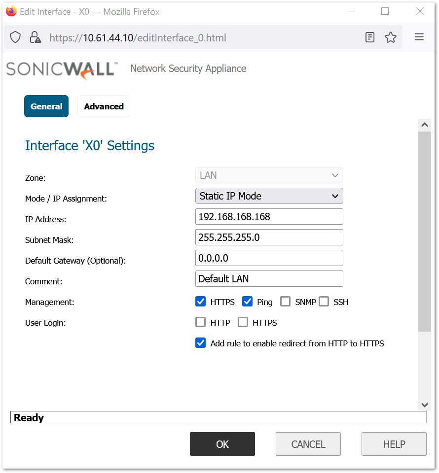
- Log in to the default LAN interface X0, using the default IP:192.168.168.168.
- Go to Network |System | Interfaces.
- Under the Interface Settings section, click the Configure icon and assign relevant IP addresses to the interfaces in the trusted and untrusted zones.
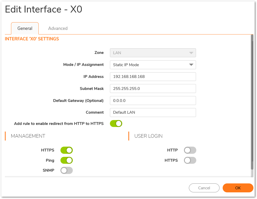
- Based on the information previously collected, assign the IP address to the interfaces in the correct subnet, you can use the default network as well.
- Enable HTTPS management and user management on the interfaces.
- Enable the desired protocols on the LAN and WAN interfaces.
- Configure the management interface with the appropriate IP addresses, net masks, and gateways, This is used only for controlling traffic management to the firewall.
- Disable DHCP server: Uncheck ‘Enable DHCP Server’ under Network | System | DHCP Server > DHCPv4 Server Settings.
- Set Firewall Host and Domain Names, Navigate to Device | Settings | Administration with Firewall Administration
i. Enter the firewall Name in the ‘Firewall Name’ box
ii. Enter the firewall Domain Name (i.e. mydomain.net) in the ‘Firewall’s Domain Name’ box and click Accept.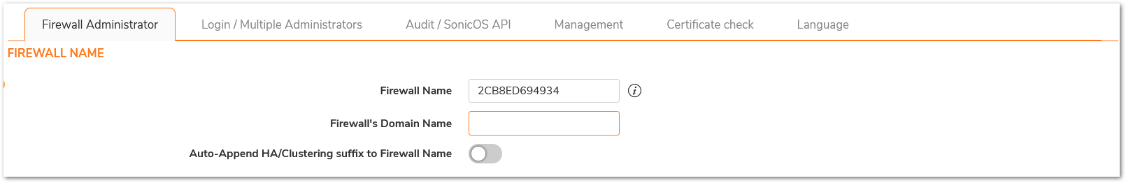
Admintrator Settings:
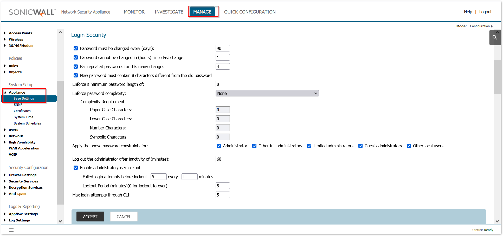
- Set Administrator Account Properties:
a. Under Firewall Administrator| Administrator Name & Password: Verify Administrator Name and set the password.
b. Under Device | Settings | Administration with Login/Multiple Administrators
i. Check ‘Password Must be Changed Every (days)
ii. Check ‘Bar repeated passwords for this many changes’ – set to ‘10’
iii. Select ‘New password must contain 8 characters different from the old password’
iv. Set ‘Enforce a minimum password length of:’ to ‘16’
v. Set ‘Enforce password complexity’ to ‘Require alphabetic, numeric, and symbolic characters’ (from the drop-down box choices)
vi. Set ‘Complexity Requirement’ to ‘2’ in each box
vii. Check all ‘Apply the above password constraints for:’ boxes
viii. Set the ‘Log out the administrator after inactivity of (minutes)’ timer to ‘10’
ix. Check the ‘Enable the administrator/user lockout’ checkbox
1. Set ‘Failed login attempts per minute before lockout’ to ‘3’
2. Set ‘Lockout Period (minutes)’ to ‘30’
x. Set ‘Max login attempts through CLI’ to ‘3’
1. Click ‘Accept’ (may require a reboot).
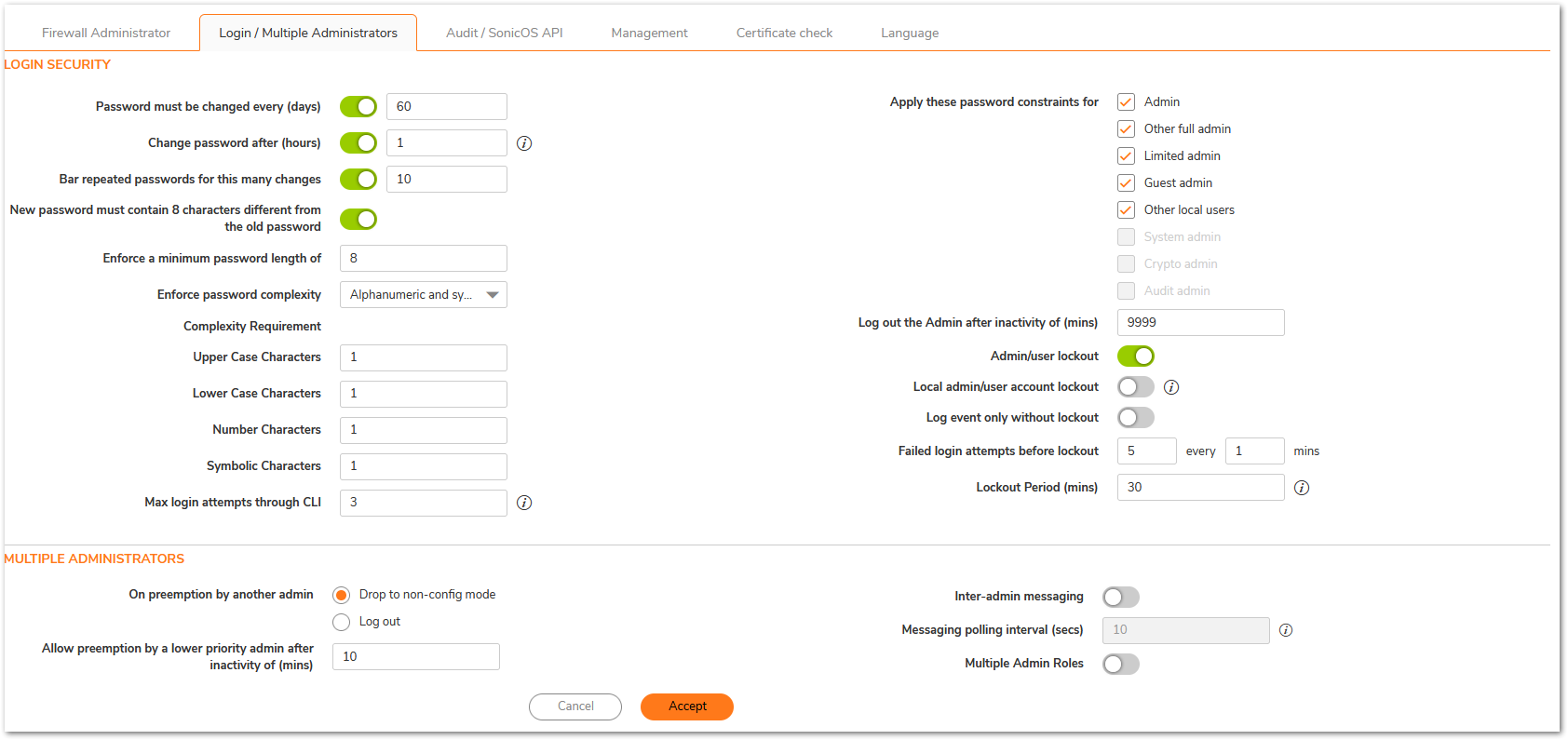
xi. Under ‘Multiple Administrators’ – Select ‘Enable Multiple Administrative Roles’

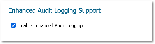
xii. Under Audit/Sonic OS API, ‘Enhanced Audit Logging Support’ – Select ‘Enable Enhanced Audit Logging’, click Accept.

User Configuration:
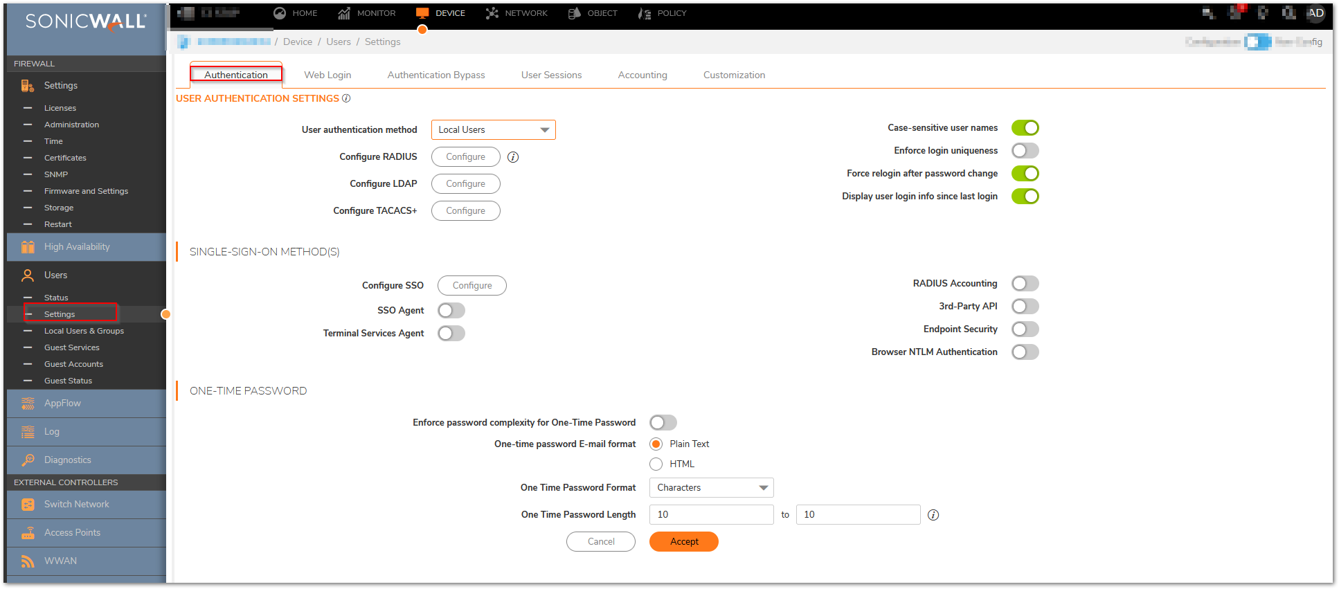
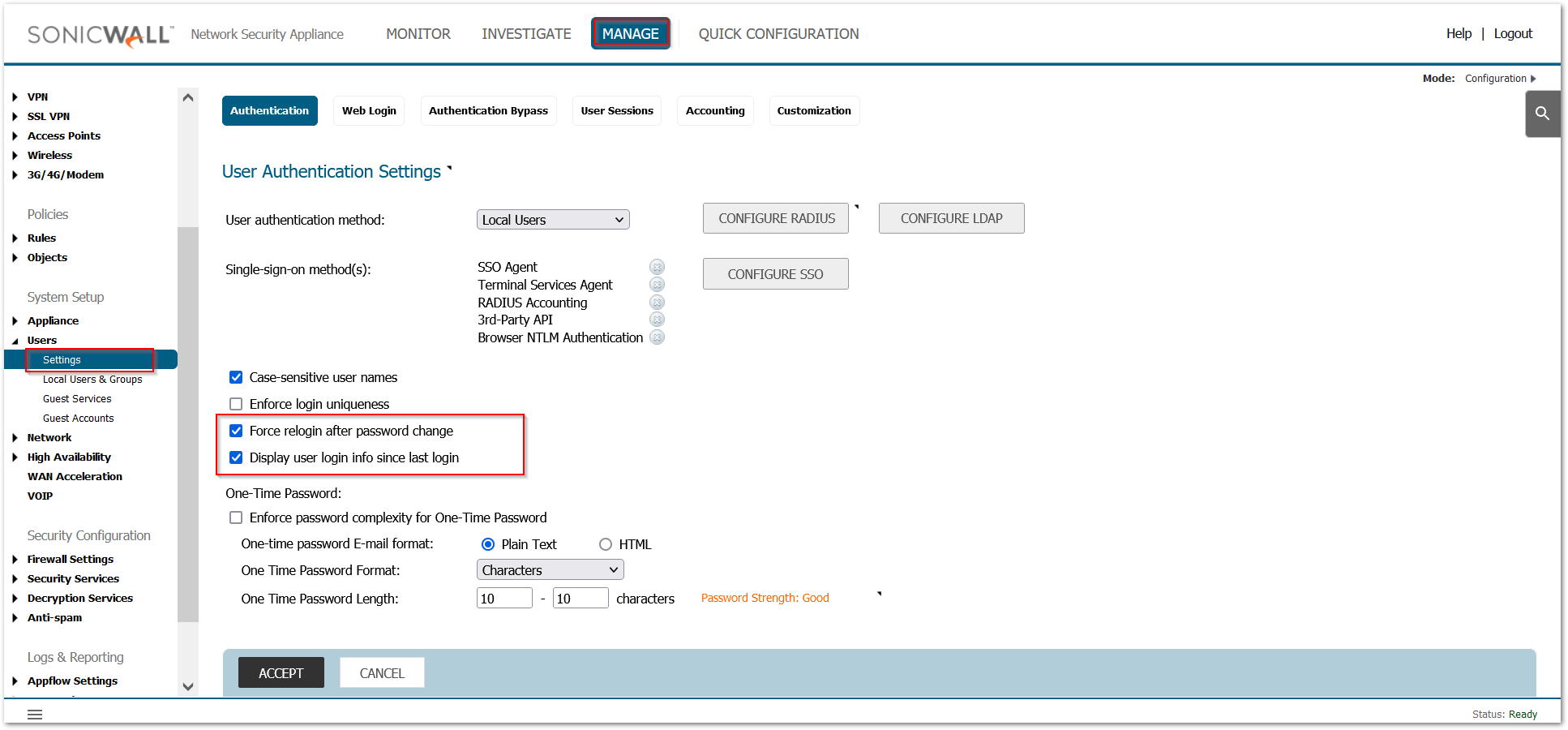
Force a new login session after a password change and display user login information since last login:
Navigate to Device | Users | Settings and Select ‘Force Relogin After Password Change’, Select ‘Display User Login Info Since Last Login’ and Click ‘Accept’.
Advanced Configuration:
For Advanced configurations in the firewall, complete the following additional steps:
- If a closed system is necessary, go to the Backend Server Communication section 12 and disable the Prevent communication with Backend servers option after the licensing protocol synchronizes, See the SonicOS Administration Guide for more information on manually updating these signatures.
- Under Diag page settings,In internal settings:
- Go to the Security Services Settings section, click Apply IPS Signatures Bidirectionally.
- Go to the ICMP Settings section, disable both ICMP packet settings.
- Under the VPN Settings section, enable the Trust Built-in CA certificates for IKE authentication and Local certificate import option.
- Click Close.
- Navigate to Device>Diagnostics and deselect “Periodic Secure Diagnostic Reporting for Support Purposes” and “Automatic Secure Crash Analysis Reporting”, the click “Accept”.
- Restart the firewall.
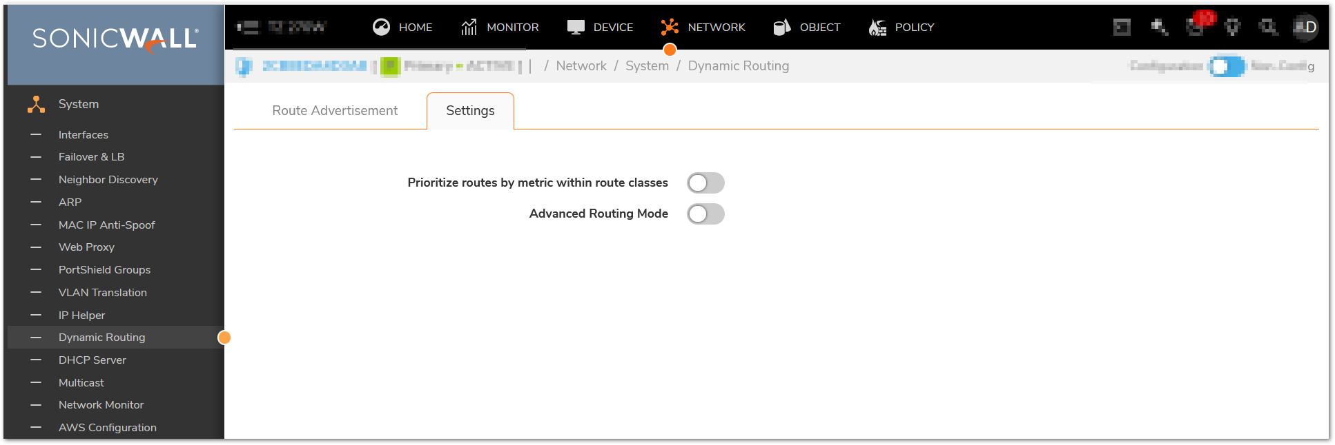
- Disable Advanced Networking:
a. In Network| System | Dynamic Routing and disable Advanced Routing.
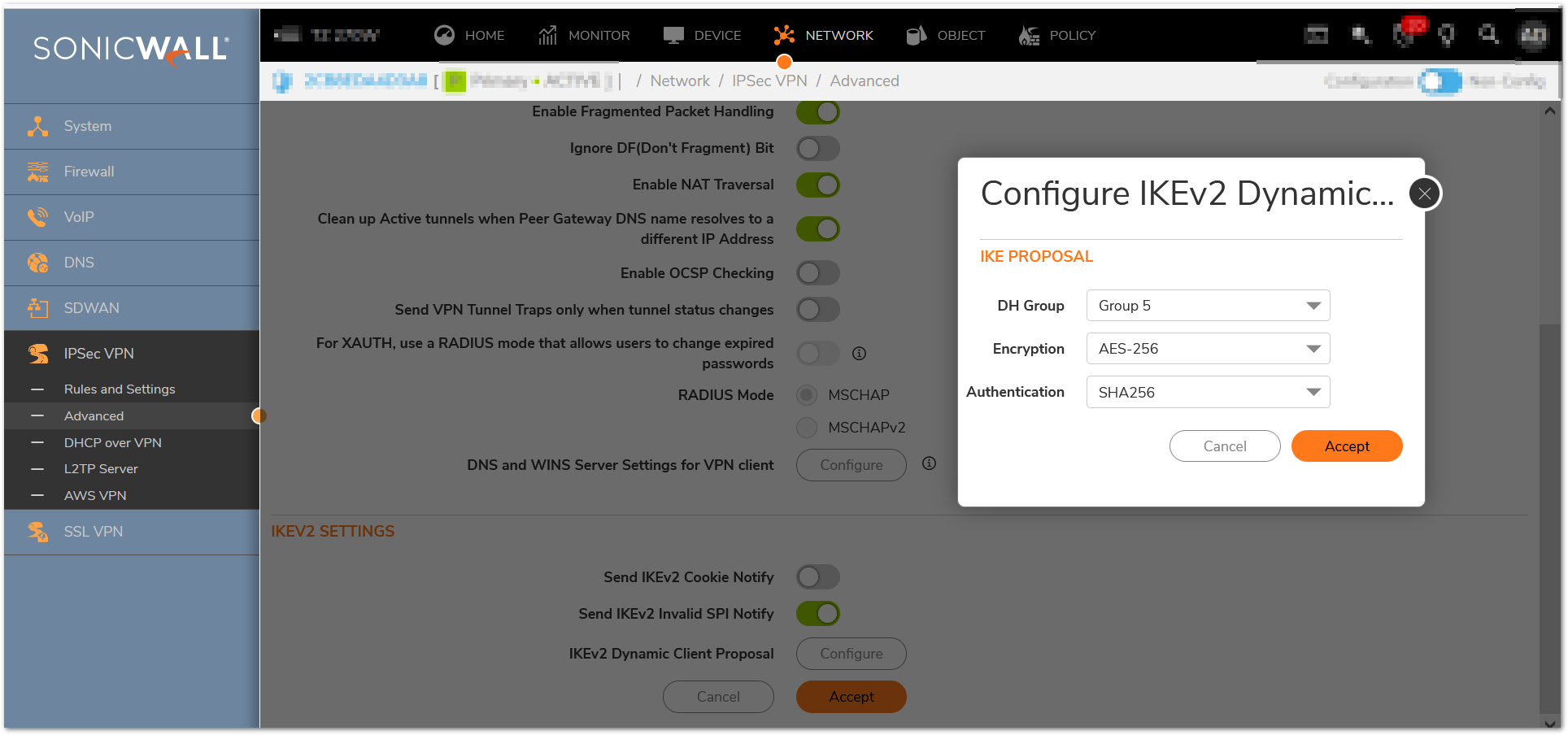
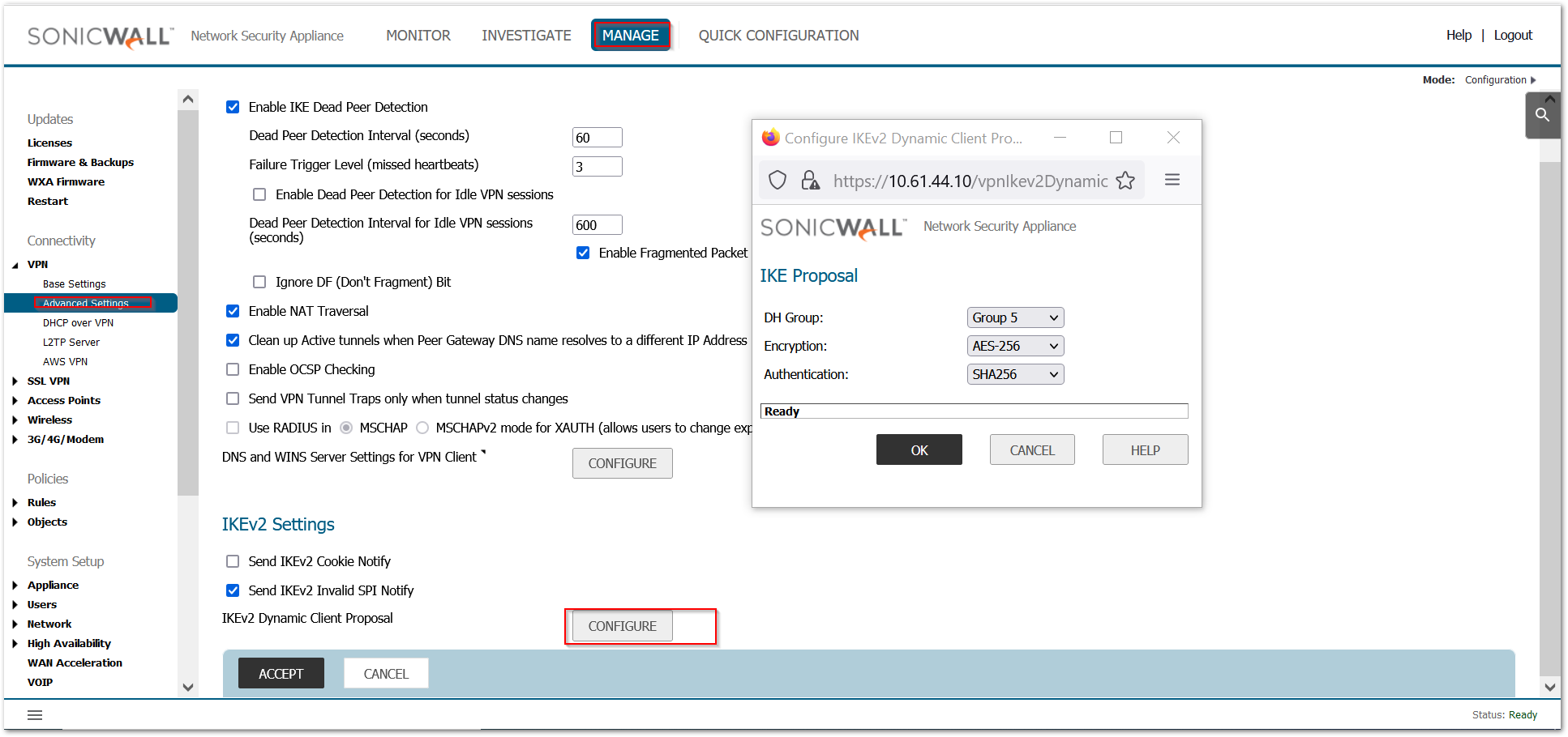
- Change IKEv2 Dynamic Client Proposal in IPSec VPN Advanced Settings to require at least DH Group 14,AES-256 encryption, and SHA-256 authentication:
a. In IPSec VPN / Advanced, navigate to ‘IKEv2 Settings’ and click the ‘IKEv2 Dynamic Client Proposal’ button
b. Change ‘DH Group’ to ‘14’ as appropriate
c. Change ‘Encryption’ to ‘AES-256’
d. Change ‘Authentication’ to ‘SHA-256’
e. Click ‘Accept’ and then ‘Accept’ again
Setting configuration:
- Turn off SSH and SNMP Management (not allowed 1 in FIPS mode):
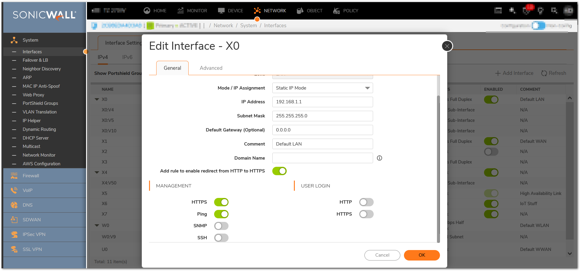
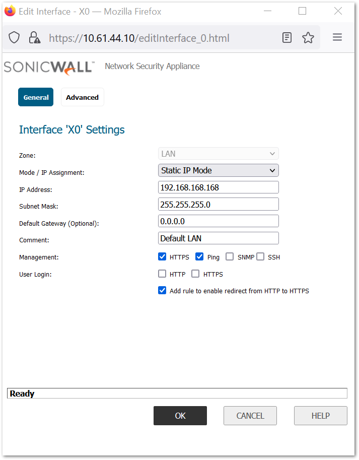
a. Navigate to Network | System | Interfaces and select the configuration icon for X0 (this assumes it’ the only interface that SSH or SNMP management might be enabled on; turn off for any others configured for SSH and/or SNMP management)
b. Deselect SSH or SNMP as appropriate.
c. Click ‘Ok’.
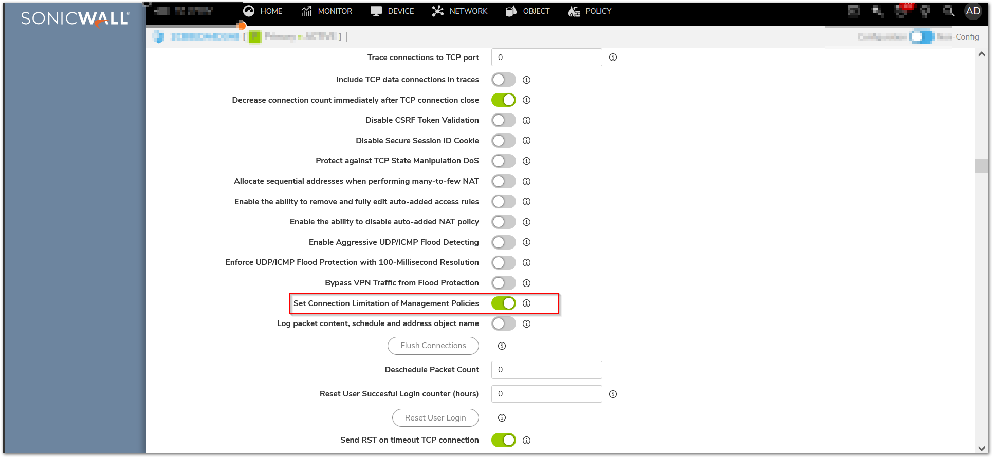
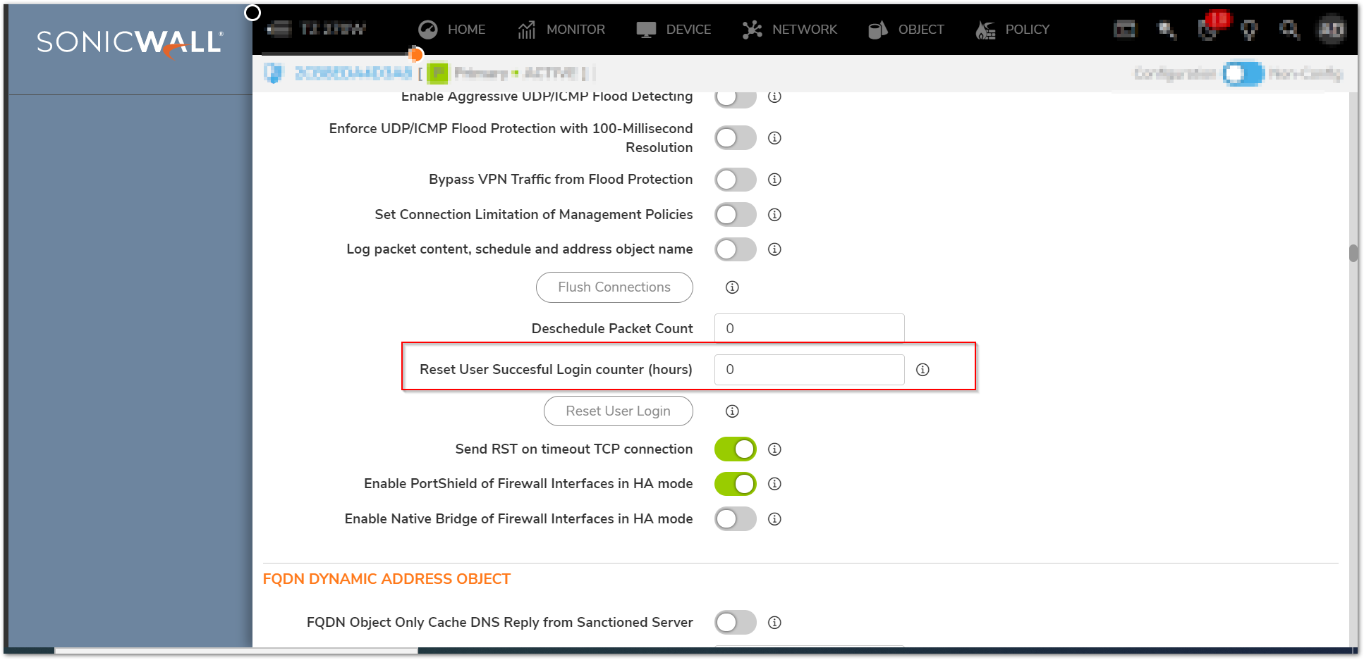
- Set session quota for each management IP (NOTE: This applies to both IPv4 and IPv6):
a. Using the browser, navigate to the diag.html page https://<IP address> /sonicui/7/m/Mgmt/settings to https://<IP address>/sonicui/7/m/Mgmt/settings/diag.
b. Check the box labeled ‘Set Connection Limitation of Management Policies’ and accept and exit internal settings.
i. NOTE: This will require an automatic reboot
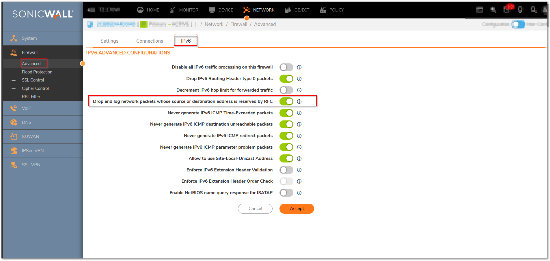
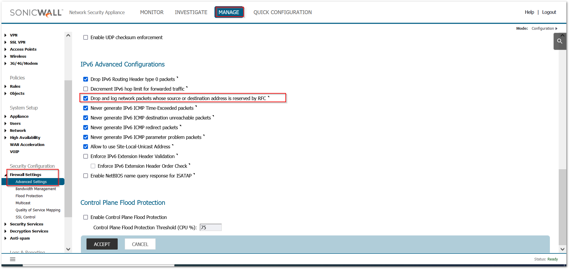
- Enable “Drop and log network packets whose source or destination address is 3 reserved by RFC”
a. In Network | Firewall | Advanced> IPV6 settings, navigate to the ‘IPv6 Advanced Configuration’ section
b. Check the option ‘Drop and log network packets whose source or destination address is reserved by RFC’ and accept it.
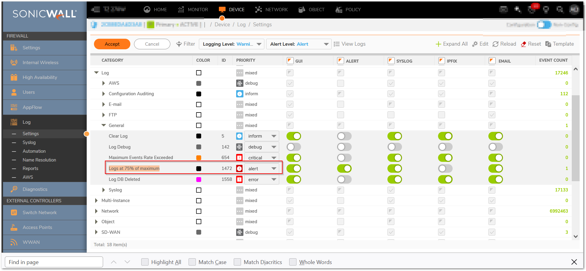
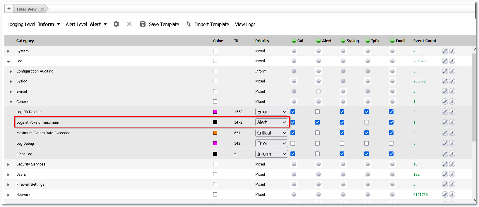
172220 Log alert when the log buffer is 75% full
Log -> Settings -> Log category -> General -> Logs at 75% of maximum: set the priority to Alert
172218 Minimum number of characters changed for password should be eight (8)
Device>Settings> Administration > Login/Multiple Administrators:

172221 Login history during a user defined time period
Diag settings, new checkbox to set the time interval for login history. Note: The system -> Status the login history is displayed. The text in the display still shows as “since system restart” but it is actually since the organizationally defined time period in the below setting.
Sample output:
• Last successful login timestamp 04/11/2016 17:30:32.000.
• Number of all user successful login attempts since system reset is 1.
Note: Login history for CAC user with LDAP
Login History for a CAC user with credentials imported from LDAP will be recorded only when the user accounts are imported from LDAP locally onto the firewall. In order for the firewall to track history of the account the user account information should be available locally on the firewall.
If using CAC with LDAP , import the LDAP user accounts locally by clicking the “Import Users” and clicking “save”.
172219 Minimum password lifetime
Device>Settings> Administration > Login/Multiple Administrators:

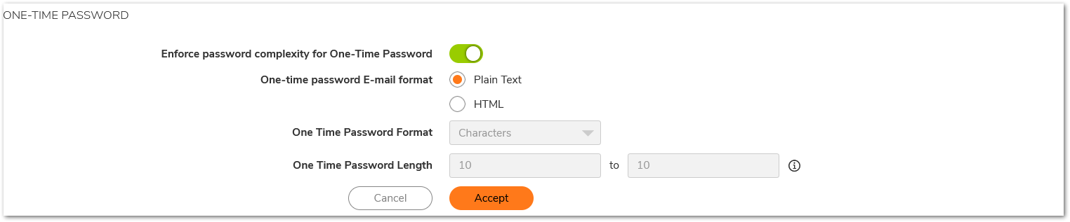
172223 Password complexity requirements should be applicable to OTP
Device> User -> Settings -> checkbox to apply password constraints to OTP
171473 Indefinite lockout of a user for wrong password(Device>Settings> Administration > Login/Multiple Administrators:)
172217 Enforce a limit of number of invalid consecutive logons within a time period

Resolution for SonicOS 6.5
This release includes significant user interface changes and many new features that are different from the SonicOS 6.2 and earlier firmware. The below resolution is for customers using SonicOS 6.5 firmware.
Interfaces Configuration:
After collecting all necessary infrastructure-related information such as the relevant service IP networks,addresses, and so on, you can begin the basic configuration. To complete the basic configuration, complete the following steps:
- Log in to the default LAN interface X0, using the default IP:192.168.168.168.
- Go to Manage |Network| Interfaces.
- Under the Interface Settings section, click the Configure icon and assign relevant IP addresses to the interfaces in the trusted and untrusted zones.
- Based on the information previously collected, assign the IP address to the interfaces in the correct subnet, you can use the default network as well.
- Enable HTTPS management and user management on the interfaces.
- Enable the desired protocols on the LAN and WAN interfaces.
- Configure the management interface with the appropriate IP addresses, net masks, and gateways, This is used only for controlling traffic management to the firewall.
- Disable DHCP server: Uncheck ‘Enable DHCP Server’ under Manage | Network| DHCP Server > DHCPv4 Server Leases Scopes.
- Set Firewall Host and Domain Names, Navigate to Manage| Appliance | Base Settings with Firewall Administration
i. Enter the firewall Name in the ‘Firewall Name’ box
ii. Enter the firewall Domain Name (i.e. mydomain.net) in the ‘Firewall’s Domain Name’ box and click Accept.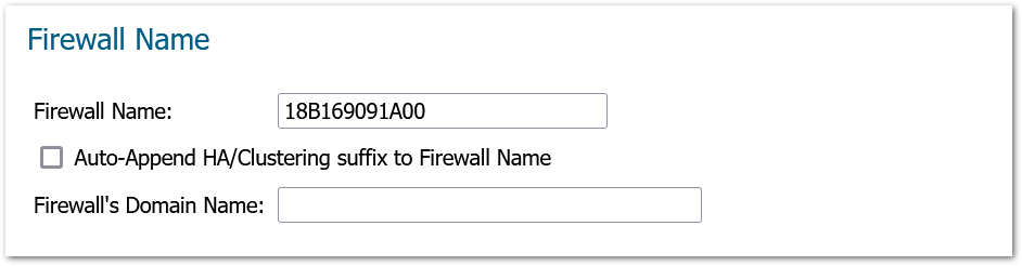
Admintrator Settings:
- Set Administrator Account Properties:
a. Under Administrator Name & Password: Verify Administrator Name and set the password.
b. Under Administration / Login Security with Login/Multiple Administrators
i. Check ‘Password Must be Changed Every (days)
ii. Check ‘Bar repeated passwords for this many changes’ – set to ‘10’
iii. Select ‘New password must contain 8 characters different from the old password’
iv. Set ‘Enforce a minimum password length of:’ to ‘16’
v. Set ‘Enforce password complexity’ to ‘Require alphabetic, numeric, and symbolic characters’ (from the drop-down box choices)
vi. Set ‘Complexity Requirement’ to ‘2’ in each box
vii. Check all ‘Apply the above password constraints for:’ boxes
viii. Set the ‘Log out the administrator after inactivity of (minutes)’ timer to ‘10’
ix. Check the ‘Enable the administrator/user lockout’ checkbox
1. Set ‘Failed login attempts per minute before lockout’ to ‘3’
2. Set ‘Lockout Period (minutes)’ to ‘30’
x. Set ‘Max login attempts through CLI’ to ‘3’
1. Click ‘Accept’ (may require a reboot).
xi. Under ‘Multiple Administrators’ – Select ‘Enable Multiple Administrative Roles’.

xii. Under ‘Enhanced Audit Logging Support’ – Select ‘Enable Enhanced Audit Logging’, click Accept.
User Configuration:
Force a new login session after a password change and display user login information since last login:
Navigate to Manage | Users | Settings and Select ‘Force Relogin After Password Change’, Select ‘Display User Login Info Since Last Login’ and Click ‘Accept’.
Advanced Configuration:
For Advanced configurations in the firewall, complete the following additional steps:
- If a closed system is necessary, go to the Backend Server Communication section 12 and disable the Prevent communication with Backend servers option after the licensing protocol synchronizes, See the SonicOS Administration Guide for more information on manually updating these signatures.
- Under Diag page settings, In internal settings:
- Go to the Security Services Settings section, click Apply IPS Signatures Bidirectionally.
- Go to the ICMP Settings section, disable both ICMP packet settings.
- Under the VPN Settings section, enable the Trust Built-in CA certificates for IKE authentication and Local certificate import option.
- Click Accept and exit the internal settings.
- Navigate to Device>Diagnostics and deselect “Periodic Secure Diagnostic Reporting for Support Purposes” and “Automatic Secure Crash Analysis Reporting”, the click “Accept”.
- Restart the firewall.
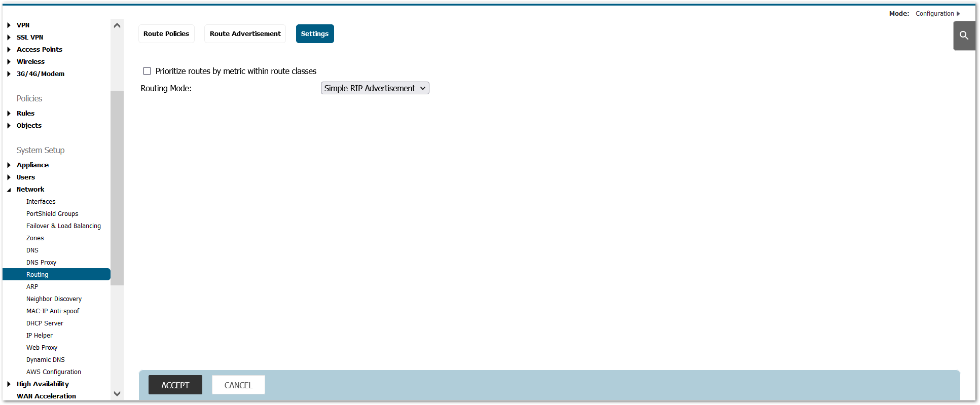
- Disable Advanced Networking:
a.In Network / Routing, change ‘Advanced Routing’ to ‘Simple RIP Advertisement’
- Change IKEv2 Dynamic Client Proposal in IPSec VPN Advanced Settings to require at least DH Group 14,AES-256 encryption, and SHA-256 authentication:
a. In IPSec VPN / Advanced, navigate to ‘IKEv2 Settings’ and click the ‘IKEv2 Dynamic Client Proposal’ button
b. Change ‘DH Group’ to ‘14’ as appropriate
c. Change ‘Encryption’ to ‘AES-256’
d. Change ‘Authentication’ to ‘SHA-256’
e. Click ‘Ok’ and then ‘Accept’ again.
Setting configuration:
- Turn off SSH and SNMP Management (not allowed 1 in FIPS mode):
a. Navigate to Network | System | Interfaces and select the configuration icon for X0 (this assumes it’ the only interface that SSH or SNMP management might be enabled on; turn off for any others configured for SSH and/or SNMP management)
b. Deselect SSH or SNMP as appropriate.
c. Click ‘Ok’.
- Set session quota for each management IP (NOTE: This applies to both IPv4 and IPv6):
a. Using the browser, navigate to the diag.html page (<IP address of host>/diag.html)
b. Check the box labeled ‘Set Connection Limitation of Management Policies’
i. NOTE: This will require an automatic reboot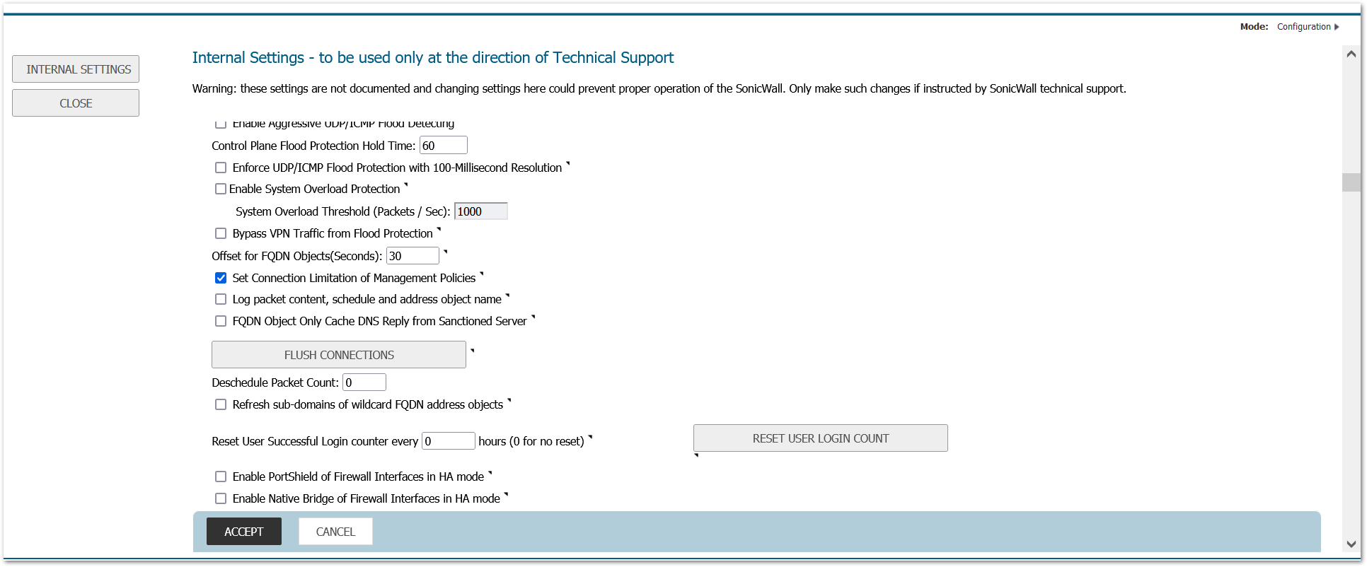
- Enable “Drop and log network packets whose source or destination address is 3 reserved by RFC”
a. In Firewall Settings >Advanced Settings, navigate to the ‘IPv6 Advanced Configuration’ section
b. Check the option ‘Drop and log network packets whose source or destination address is reserved by RFC’ and accept it.
172220 Log alert when the log buffer is 75% full
Log -> Base setup -> Log category -> General -> Logs at 75% of maximum: set the priority to Alert
172218 Minimum number of characters changed for password should be eight (8)
Manage>Appliance> Base settings > Login security:

172221 Login history during a user defined time period
Diag settings, new checkbox to set the time interval for login history. Note: The system -> Status the login history is displayed. The text in the display still shows as “since system restart” but it is actually since the organizationally defined time period in the below setting.

Sample output:
• Last successful login timestamp 04/11/2016 17:30:32.000.
• Number of all user successful login attempts since system reset is 1.
Note: Login history for CAC user with LDAP
Login History for a CAC user with credentials imported from LDAP will be recorded only when the user accounts are imported from LDAP locally onto the firewall. In order for the firewall to track history of the account the user account information should be available locally on the firewall.
If using CAC with LDAP , import the LDAP user accounts locally by clicking the “Import Users” and clicking “save”.
172219 Minimum password lifetime
Manage>Appliance> Base settings > Login security:

172223 Password complexity requirements should be applicable to OTP
Manage> Users -> Settings -> checkbox to apply password constraints to OTP
171473 Indefinite lockout of a user for wrong password(Manage>Appliance> Base settings > Login security:)
172217 Enforce a limit of number of invalid consecutive logons within a time period

Related Articles
- How to verify if configuration file imported into a firewall came from SonicWall’s Migration tool?
- Types of Group VPN / Global VPN Client Scenarios and Configurations
- Configuring SMTP Real-Time Black List (RBL) Filtering on the SonicWall
 NOTE: Settings import from Gen6/6.5 is only supported with
 CAUTION: Settings from a higher firmware version cannot be imported into a lower version of firmware. For example it is not supported to import 6.5.3.x settings into 6.5.1.x firmware.


 TIP: When importing settings to a TZ Series Firewall, make sure to disable Portshield on the destination Firewall beforehand to ensure the interface configuration will be updated.