This article describes how to recover a bricked USW-Flex-Mini via recovery mode. The first step in the recovery process is to prepare a web server. See the subsections below on how to do that on each of the different operating systems: Windows, macOS and Ubuntu/Debian and then continue to the recovery instructions once that is done.
The first step in the recovery process is to prepare a web server. See the subsections below on how to do that on each of the different operating systems: Windows, macOS and Ubuntu/Debian.
How to Prepare a Web Server on Windows
1. Download Python for Windows (Executable Installer) here.
2. Open the downloaded file and make sure you select Add Python x.x to PATH during installation.
3. After the Python installation open Command Prompt as Administrator and confirm that Python is installed correctly with the command below:
python -V
4. Create a directory for the web server by running the commands below:
mkdir c:\webserver
cd c:\webserver
5. Start the Python web server on port 80. Note that the version of Python can be found with the command from step 3:
3. Create a directory for the web server by running the commands below:
cd ~
mkdir webserver
cd webserver
4. Start the Python web server on port 80. Note that the version of Python can be found with the command from step 2:
Python 3.x:
sudo "${python_version}" -m http.server 80
Python 2.x:
sudo "${python_version}" -m SimpleHTTPServer 80
How to Recover a USW Flex Mini
1. Prepare a web server as explained above, and set the server / computer’s IP to a static 192.168.1.99. The way to set a static IP on a computer will vary from platform to platform. Find instructions on how to do that in your product’s documentation (Windows, macOS or Ubuntu/Linux).
2. Download the latest firmware (found in Downloads), rename the binary to fwupdate.bin and place it in the directory that was created earlier (webserver).
3. Power down the switch by unplugging from the power source.
4. Press the switch’s reset button and hold it down as you provide power to the switch. Hold the reset button down for over 10 seconds during boot up. The LED pattern should be: blue-white-off blinking.
5. The USW-Flex-Mini should be updated after a while.
The method described in this article should help recover a “bricked” UniFi AP. This method will not void the device warranty, whereas opening the chassis for serial TTL will void your warranty. Most soft brick issues will be resolved via this procedure. If your issue continues unresolved, it might indicate a hardware issue that cannot be resolved via software. Feel free to contact support if you believe this to be the case.IMPORTANT:When Recovering UAP Gen1 Devices, The device itself will need approximately 5 minutes to finish recovering after the put command is entered.
TFTP for Windows
1. Prior to beginning the TFTP recovery, download the firmware for the device needed by visiting the UniFi Downloads section. Navigate to the UAP in question using the menu on the left, and find the latest firmware file. Confirm it is a .bin firmware file and not the UniFi Network application software file before downloading.
2. Once the correct firmware has been identified, download it and save it on your computer.
3. Unplug the ethernet cable from the UniFi AP.
4. Using a paperclip press and hold the UniFi AP’s reset button. Make sure you can feel it being depressed by the paperclip. Do not release the button until step 6.
5. While keeping the reset button pressed in, plug the ethernet cable back into the AP. Keep the reset button depressed until you see the device’s LED flashing in upgrade mode (read about LED patterns in this article). This may take up to 25 seconds. User Tip: The UAP will not respond to ping requests while in TFTP recovery mode, but will respond to ARP requests.
6. You may release the reset button. Now the device is in TFTP transfer mode.
7. Set a static IP on your Computer’s NIC. A static IP of 192.168.1.25, a subnet of 255.255.255.0 and gateway of 192.168.1.20 will work.
8. Plug the UniFi PoE injector’s LAN cable directly to your computer.
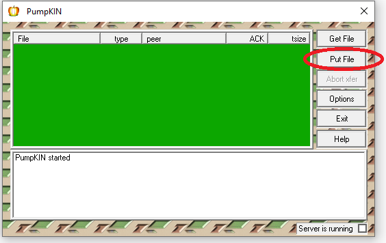
9. This example uses the Pumpkin TFTP software, which you can download here (clicking link will download the .exe file immediately) and disable the firewall or allow the Pumpkin connection. Click on “Put File”.
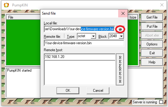
10. In “Local Files” browse for the firmware you downloaded and saved previously (in step 1).
11. In the “Remote host” field enter the gateway you had predetermined (192.168.1.20), then click OK.
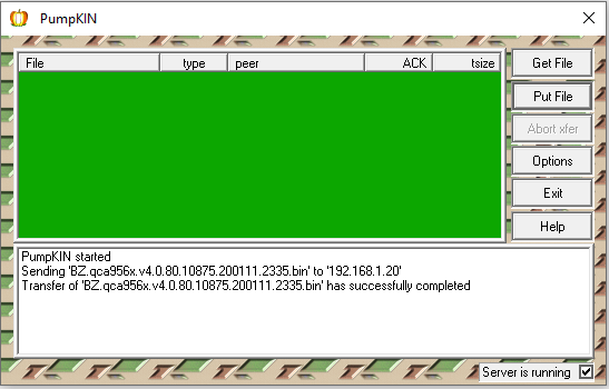
12. At this point, the file should begin transferring. The firmware will upgrade now and the device will automatically reboot once it has finished. Do not reboot it yourself.
TFTP for Linux & macOS
1. Prior to beginning the TFTP recovery, download the firmware for the device needed by visiting the UniFi Downloads section. Navigate to the UAP in question using the menu on the left, and find the latest firmware file. Confirm it is a .bin firmware file and not the UniFi Network application software file before downloading.
2. Once the correct firmware has been identified, download it and save it on your computer. You will need to know the exact path to your file, so for this example, we are moving the downloaded firmware file to /Users/username/.
3. Go to System Preferences > Network and set your computer’s network IP address to 192.168.1.25, subnet 255.255.255.0 and gateway 192.168.1.20. User Tip: Take note of what your IP address is before changing it. You will have to revert back to the original IP address on step 12.
4. On macOS Open Applications > Utilities > Terminal and type:
tftp
On Linux, open the command line application of choice and type the following (substituting the bolded path and firmware name for the name of the file you downloaded in step 2 and the path to where it is saved):
5. A tftp> command prompt will appear. You are ready to reset the AP and connect it to your computer, while it’s in “upgrade mode”.
6. Unplug the ethernet cable from the UniFi AP.
7. Using a paperclip press and hold the UniFi AP’s reset button. Make sure you can feel it being depressed by the paperclip. Do not release the button until step 9.
8. While keeping the reset button pressed in, plug the ethernet cable back into the AP. Keep the reset button depressed until you see the device’s LED flashing in upgrade mode (read about LED patterns in this article). This may take up to 25 seconds. User Tip: The UAP will not respond to ping requests while in TFTP recovery mode, but will respond to ARP requests.
9. You may release the reset button. Now the device is in TFTP transfer mode.
10. On the TFTP command line in Terminal, paste these four lines and hit enter:
connect 192.168.1.20
binary
rexmt 1
timeout 60
Click to copy
11. Type the command put followed by the path to the firmware downloaded in step 2 and hit enter. Following the example mentioned in step 2, something similar to this would be typed into the Terminal window:
put /Users/Alex/BZ.qca956x.v3.9.27.8537.180317.1235.bin
IMPORTANT:Remember you must substitute the bolded path and firmware file name with your own path and file name.
Once it is successful, you will see something like this in the Terminal window (bolded words will be different for each user):
tftp> connect 192.168.1.20
tftp> binary
tftp> rexmt 1
tftp> timeout 60
tftp> put /path/firmware.bin
Sent x bytes in y seconds
The file should begin transferring at this point. The firmware will upgrade and the device will automatically reboot once it has finished. Do not reboot it yourself.
12. Re-connect the PoE injector’s LAN cable into your router. Restore the network IP back to what it was before.User Tip: If your device is having trouble getting adopted by the UniFi Network application after this process, try forgetting the device by going to the UniFiDevices section, clicking on the UAP in question and then within the properties panel that pops up, go to Config (gear icon) > Manage Device > Forget this device. Click on the “Forget” button and try the process again.
This article explains best practices for configuring larger UniFi networks with AirPlay/Chromecast devices. For efficient and reliable channel utilization, networks with more than 100 WiFi clients will need the multicast block option to be enabled on each of their SSIDs. This guide is especially useful for schools, stadiums, public venues, or similar networks.
Note: This guide applies to a network with a UniFi Security Gateway, UDM, or UDM-Pro. If your network does not have one of these, the steps may need to be adapted.
Creating a ChromeCast/AirPlay Network
Once your UniFi Network scales beyond a certain number of WiFi clients, it is important to ensure that every AP’s WiFi channel continues to be used efficiently. The broadcast traffic from more than 100 clients is typically high enough that WiFi performance may start to degrade. We always recommend enabling the multicast block option setting for larger networks.
However, this option causes a problem with users that would like to use their ChromeCast/AirPlay devices on the same WiFi network, because those devices will no longer hear the MDNS broadcasts from other devices on the network. They will no longer be discoverable.
In order to gain the performance benefits of multicast block while still maintaining discoverability to these WiFi clients, please follow these steps:
Go to Settings > WiFi and select on the SSID to check that multicast block is enabled if it has more than 100 clients on it.
Create a separate SSID/VLAN for the ChromeCast/AirPlay clients.
Go to Settings > Networks, and add a New Network.
Go to Settings > WiFi, and add a new WiFi Network, ensuring that the Network from Step “a” is selected, instead of LAN.
Go to Settings > Advanced Features > Advanced Gateway Settings > Multicast DNS and enable Multicast DNS, then click Apply Changes.
Forget the old network on your ChromeCast/AirPlay clients and connect them to the new WiFi Network.
Test Discoverability from the appropriate mobile apps.
DNS tunneling is a technique that encodes data of other programs and protocols in DNS queries, including data payloads that can be used to control a remote server and applications. Because of this, DNS tunneling – and DNS exfiltration associated with it by threat actors – is of great concern to many IT and SecOps teams. Fortunately, new developments in the Cisco Umbrella DNS cache system allow for faster and more reliable detection of DNS tunneling and exfiltration events.
How Does DNS Tunneling Work?
DNS tunneling revolves around the transfer of data. So, if we have:
Input Data data – Name: Alice, Age: 25, SSN: 123-45-678
Using DNS exfiltration, we can encode and send this data placed in several subdomains of the domain under our control as a single entry:
Or, we can use multiple entries using multiple queries to large numbers of domains:
jzqw2.zj2if.my.tunnel.com
wgsy3.ffraw.my.tunnel.com
ozj2g.i2syu.my.tunnel.com
2tjy5.dcmrt.my.tunnel.com
Users can abuse this technique – as seen in Fig. 1 below – by installing a free DNS tunneling tool to bypass IT policies and/or monitoring. They can also use this technique to bypass network authorization to obtain free internet access in hotels and airports.
Fig. 1
Attackers can use outbound DNS requests to send encoded exfiltrated data to their infrastructure – as seen in Fig. 2 below – or use DNS responses to send commands to compromised systems and manage infected devices remotely.
Fig. 2
Improvements to DNS Tunneling Realtime Detection
Today, we’re thrilled to announce that organizations have a powerful new ally to protect against data exfiltration and unauthorized DNS tunnels in their networks. Cisco Umbrella has developed a new proprietary cache within our DNS resolvers to work alongside our machine learning modules. Our newest machine learning module is tuned to detect data exfiltration and DNS tunneling events.
This new module monitors DNS traffic for behavioral patterns and traffic exfiltrating data, efficiently building enough information to detect and block data exfiltration. And, in the event circumstances and domain reputations change, this module will correct itself and let traffic through.
We made this update because, over the past couple of years, we’ve seen organizations more productive and more connected amidst the new reality of working digitally during the pandemic. The explosion of logins and bandwidth, though, has at times come with reductions in digital security. Data exfiltration has become a new reality, and one hole attackers punch is in the DNS.
Powering Improvements With a Revolutionary DNS Cache
The technology stack powering Cisco Umbrella’s DNS resolvers handles blistering loads of DNS traffic from ISPs, global organizations, municipalities, schools, and homes. Building on this, we’ve hacked the heart of the DNS resolver – the cache. And while we dig into the details of this new functionality in our DNS tunneling solution brief, we also want to provide you with an overview here.
The cache of a DNS resolver enables serving the swell of global traffic without fault, outage, and ease. It also insulates the backbone of the internet from being overwhelmed with identical queries. Caches store data locally so that it can be served quicker.
Tunneling Cache
The tunneling cache enables us to glue together a sequence of queries that are otherwise distinct atomic events. With proprietary key and data fields, we seamlessly incorporate rapid cache updates unbeknownst to web surfers. We maintain lightning speed throughout by merging incoming data fields using tricks found in probabilistic algorithms. Gluing together each individual’s DNS queries provides access to a rich amount of information, otherwise hidden. Organizations can now get personalized DNS tunneling monitoring, detection, and enforcement in real time.
Encryption Payloads
We pair the new DNS cache with a lexical engine highly trained at identifying encrypted messages. Our researchers dug into various encryption protocols and created a stateful algorithm capable of churning through every character transition in a domain name and identifying encryption payloads with high fidelity.
Take DNS-Layer Security to the Next Level
Cisco Umbrella analyzes internet activity to uncover known and emergent threats in order to protect users anywhere they go. Together, these capabilities power Umbrella to predict and prevent DNS tunneling attacks before they happen. Enabling this security category reduces the risk of DNS tunneling and potential data loss. Organizations can choose to block users from using DNS tunneling VPN services, or they can monitor the results in reports, providing flexibility to determine what is suitable given their risk tolerance.
Address your DNS blind spot by enforcing security over port 53 both on and off the corporate network. Request a personalized demo of Cisco Umbrella today to explore how this exciting new feature can help protect your enterprise.
Last year threw a lot at cybersecurity teams, from the emergence of several high-profile cyberattacks to the revelation of widespread vulnerabilities. As we all move into 2022, odds are your team is re-thinking your cybersecurity strategy to help make your organization more resilient and flexible. This should involve an evaluation of your cybersecurity solutions, as they impact the implementation and effectiveness of any strategies your team creates.
In our ebook 7 ways to strengthen your security in 2022 and beyond, we discuss the different ways you can amplify and extend your cybersecurity stack this year using Cisco Umbrella. But if you’re looking for some tips to get you started, here are three things to keep in mind as you plot out your cybersecurity strategy:
1. Make Sure Your Cybersecurity Solutions Don’t Impact Network Speeds
The use of internet resources and cloud services was on the rise before the COVID-19 pandemic. Now that employees have spread out – collaborating with coworkers and performing business-critical tasks from anywhere they have internet access – cloud-based tools have become more critical than ever.
This means that an effective cybersecurity strategy needs to balance the implementation of strong protections against the need for minimal latency on the company network. From a business perspective, cyber safety can’t come at the expense of speed.
In order to maintain this balance, take a look at your cybersecurity solutions and evaluate the following:
Routing Algorithms – Frequently, having fast and secure internet access comes down to a cybersecurity vendor’s data center network and routing algorithms. Make sure your cybersecurity solutions come backed by a robust global data center network and transparent routing protocols with automated failover to the fastest available servers. This minimizes latency, regardless of where users on your network are located.
Peering Relationships – Peering relationships allow cybersecurity vendors to minimize latency without compromising on security. As you reevaluate your cybersecurity strategy in the coming year, make sure your vendors have peering relationships with large cloud service providers your organization relies on. This allows employees to easily access the tools they need without introducing added latency.
Keeping network speeds in mind while you refine your cybersecurity strategy for the upcoming year can improve employee satisfaction, affect executive buy-in, and have an impact on your organization’s bottom line.
2. Strengthen Cybersecurity Infrastructure to Reduce Disruptions
Last year, we all experienced more than our fair share of network disruptions, outages, and downtime. Several of these events were impactful enough to make it into the news cycle. And while an outage isn’t the same thing as a cyberattack, your cybersecurity strategy should include finding solutions that are designed to reduce downtime instead of causing it.
Take some time to review the track record of your vendors. For example, do they have a proven record of resiliency and uptime? Better yet, can they handle infrastructure disruptions without passing those disruptions onto your users? For example, the unique DNS logging features included in Cisco Umbrella DNS-layer security can be used during certain events – like the 2021 Akamai outage – to keep users connected to business-critical cloud tools despite provider outages.
3. Make Sure Your Cybersecurity Strategy Includes Guest WiFi Considerations
Between the move to a hybrid work model and the gradual reopening of public spaces, odds are you’ll find more employees and clients using your guest WiFi in the coming year. So, it’s essential to make sure that both your private and guest WiFi networks have the speed users desire and the protection you need.
Does your suite of cybersecurity solutions provide your team with the ability to filter content and enforce security protocols over your guest WiFi network? Does your security stack allow you to maintain a single IP address for your entire enterprise, streamlining the management of guest WiFi security policies? Finally, can your cybersecurity solutions handle the uptick in user traffic that guest WiFi causes without increasing latency? If the answer to any of these questions is “no,” it may be time to think about adjusting your security stack.
Looking for More Ways to Strengthen Your Cybersecurity Strategy?
Blue and White status LEDs apply to all our UniFi access points, routers, switches and the UDM (base model) with the exception of the legacy devices: UAP, UAP-LR, UAP-Outdoor5.
Legacy UAPs have Amber and Green LED on the front of the unit. See this section for legacy AP LED patterns.
The animations are for illustrative purposes – the speed of the flashing or strobing patterns below might differ slightly with that of the device.
While the LED patterns below are shown for Access Points, the rest of the UniFi device LED patterns have the same meaning.
Flashing White / Off every 1/2s
The device is initializing and booting up
Steady White
The device is awaiting Adoption
Slow flashing Blue (UDM only)
A client device is connected to the UDM via Bluetooth
Steady Blue
The device is adopted and is in normal operating mode
The device firmware is currently being upgraded – do not interrupt the process!
(UDM will flash only white during an upgrade)
Blue and flashing Off every 5s
Access Point has lost network connectivity and is searching for wireless uplink
Rapid flashing Blue / Off
The device “Locate” feature was activated in the UniFi Network application
Flashing White-Blue-Off
The device is in TFTP mode.
To enable this mode:
Hold the reset button before applying power
Continue to hold the reset button until this LED sequence appears
If this wasn’t intentional, please check if the device’s reset button isn’t jammed (it should click when pushed).
LED Off
The device is offline.
Verify the Power, POE, and Ethernet cables to troubleshoot.
UniFi Bridge to Bridge (UBB)
Aside from the statuses described above, the UBB has two additional ones:
Red with Circulating Blue LED
The 60 GHz link cannot be established or has dropped due to bad weather. If the UBB fails over to 5 GHz, the LED will remain red. When the 60 GHz link is re-established, the LED will turn blue or the custom color you selected in the UniFi Network application.
Note: If the other bridge device is within range and the UBB LED is red, we recommend adjusting the UBB’s position to enhance the signal strength.
Green
If the Alignment Tool enabled in the UniFi Network application, a green LED means the UBB devices are properly aligned.
Note: If the other bridge device is within range and the UBB LED is green and red, we recommend adjusting the UBB’s position until the LED is green.
Legacy Amber and Green LED patterns
Applies to: UAP, UAP-LR, UAP-Outdoor5.
Flashing Amber / Off every 1/2s: The AP is initializing and booting up
Steady Amber: The AP is awaiting adoption
Steady Green: The AP is adopted and is in normal operating mode (AP is broadcasting SSIDs)
Strobing Amber / Off: If this happens, power cycle the AP and reach out to our support team if it doesn’t change the LED pattern
Quickly flashing Amber / Green: The AP firmware is currently being upgraded – do not interrupt the process!
Green and flashing Off every 5s: AP has lost network connectivity and is searching for wireless uplink
Rapid flashing Green / Off: The device “Locate” feature was activated in the UniFi Network application
Flashing Amber-Green-Off: The device is in TFTP mode. To enable this mode, hold the reset button before applying the power and continue to hold it until this LED sequence appears. If this wasn’t intentional, please check if the device’s reset button isn’t jammed (it should click when pushed).
LED Off: The device is offline. Verify the Power, PoE, and Ethernet cables to troubleshoot.
LED patterns for ports
The ports of UniFi Security Gateways and UniFi Switches have a different type, number, and location.
Please make sure to reference your specific device model’s Quick Start Guide (QSG) for the exact location and description of its ports.
Console Port’s right LED (in the applicable devices):
LED Off: Power Off
LED Green: Power On
Speed/Link/Act (right LED ports other than Console):
LED Off: No Link
LED Amber: Link Established at 10/100 Mbps
LED Flashing Amber: Link Activity at 10/100 Mbps
LED Green: Link Established at 1000 Mbps
LED Flashing Green: Link Activity at 1000 Mbps
PoE (left LED on ports of applicable devices):
LED Off: No PoE
LED Amber: IEEE 802.3af/802.3at
LED Green: 24V Passive
SFP (in the applicable devices):
LED Off: No Link
LED Green: Link Established at 1 Gbps
LED Flashing Green: Link activity at 1 Gbps
See specific port LED information in the Hardware Overview section (between pages 5 and 6) of the Quick Start Guides (QSG). You can find the QSGs in the Documentation section of our UniFi Downloads page, by searching for the device in question in the left hand menu.
LED patterns for PoE Adapters
LED is Off: PoE is Off.
LED is On and steady: PoE is functioning as it should.
LED is blinking: this is not a configured state, this may indicate that the device is not connected properly, or that something is wrong with the cable.
How to disable device LEDs
The device status LEDs can be disabled for all the site, or only for specific UniFi devices.
To enable/disable status LEDs throughout a site, go to to Settings > Site on the UniFi Network application and edit the LED feature in the Services section.
To configure specific devices individually:
Go to the Devices section and click on the device you wish to edit to bring up the Properties panel
Go to Config > General > LED and switch the Site Settings to On or Off.
This article describes how to access the emergency recovery user interface (UI) and recover a UniFi Cloud Key or a UniFi Cloud Key Gen 2 (UCK-G2-PLUS and UCK-G2 models). From this recovery UI you can reset it to factory defaults, reboot it, power it off and upgrade the firmware.NOTES & REQUIREMENTS:
To upgrade the firmware, you will need to download a firmware file (.bin) for the Cloud Key found in our Downloads page. Use the left hand menu to select the correct Cloud Key model and find the newest firmware available.
To access this interface you will need to know the IP address of the Cloud Key (visible in the device screen).
For second generation Cloud Keys (UCK-G2 and UCK-G2-PLUS) follow these steps to access the Emergency Recovery UI:
Power off the system.
Press and hold the reset button and then power on the Cloud Key by connecting it to the power source.
Cloudkey G2:
CloudKey G2 Plus
Keep the reset button pressed for about 10 seconds, or until you see the recovery LED pattern in a loop (blue – off – white). The LCD screen on the front panel will also read “RECOVERY MODE.”
Once the LED is flashing in the recovery mode pattern, open your browser and type the IP address for the Cloud Key, visible on the device’s screen. The IP address comes from your DHCP server, if you can’t access DHCP, the fallback IP will work: 192.168.1.30. However, keep in mind that if your Cloud Key does have a IP address assigned by the DHCP server, the fallback IP will not work.
You should be taken to the Recovery Mode screen. From here you can reset, reboot, power off and most importantly you can upload an updated firmware bin file.
To update the firmware, go to the Downloads page, find the correct Cloud Key model on the left hand menu and then click on the download button, read and accept information, and then download the firmware file to your computer to upload in the Recovery Mode UI. Once it is uploaded you will have to reboot the Cloud Key to complete the firmware upgrade.
The LED will flash white while upgrading and then a steady white when it is ready.
Cloud Key Gen 1 Emergency Recovery
For first generation Cloud Keys follow these steps to access the Emergency Recovery UI:
Power off the system.
Press and hold the reset button and then power on the Cloud Key by connecting it to the power source.
Keep the reset button pressed for about 10 seconds, or until you see the recovery LED pattern in a loop (blue – off – white).
Once the LED is flashing in the recovery mode pattern, open your browser and type the IP address for the Cloud Key. The IP address comes from your DHCP server, if you can’t access DHCP, the fallback IP will work: 192.168.1.30. However, keep in mind that if your Cloud Key does have a IP address assigned by the DHCP server, the fallback IP will not work. If you are using a Gen 2 Cloud Key you will see its IP address on the device screen.User Tip: If you don’t know your Cloud Key’s IP address, you can use thearp -a SSH command or software such as nmap to find the IP address.
You should be taken to the Recovery Mode screen. From here you can reset, reboot, power off and most importantly you can upload an updated firmware bin file.
To update the firmware, go to the Downloads page, find the correct Cloud Key model on the left hand menu and then click on the download button, read and accept information, and then download the firmware file to your computer to upload in the Recovery Mode UI. Once it is uploaded you will have to reboot the Cloud Key to complete the firmware upgrade.
Once it is uploaded you will have to reboot the Cloud Key to complete the firmware upgrade.
The LED will flash white while upgrading and then a steady white when it is ready.
They’re not interested in peace on earth, a hippopotamus or their two front teeth. You won’t find them decking the halls, dashing through the snow or even up on the housetop. But that doesn’t mean cybercriminals aren’t out in force this time of year — and they’re relying on you being too wrapped up in your holiday preparations to see them coming.
They’re successful far too often: The last quarter of 2020 saw by far the most ransomware, with attacks in November reaching an all-time high in an already record-breaking year. If 2021 follows suit, this could be the worst holiday season for ransomware SonicWall has ever recorded — but fortunately, there are many things you can do to minimize your risk:
It’s the Most Wander-ful Time of the Year: Travel Tips
Roughly 63% of American adults plan to travel for the holidays this year — a nearly 40% jump over last year, and within 5% of 2019 levels. While it’s easy to become preoccupied by traffic jams, flight delays and severe weather, don’t forget that attackers love to leverage this sort of chaos. Follow these five travel best practices to keep cybercriminals grounded this holiday season.
1. Free Wi-Fi =/= Risk-Free Wi-Fi
When you stop for a coffee during your layover, or stumble into a greasy spoon on hour nine of your road trip back home, you might be tempted to log on to the free Wi-Fi. But unless your organization has implemented zero-trust security, beware. Try bringing a novel and coloring books to keep everyone occupied on the road, and if you must connect, use a VPN to access employer networks and avoid logging in to your bank, email or other sensitive accounts. Because some devices may try to connect to these networks automatically, you may need to disable auto-connect to fully protect against man-in-the-middle and other attacks.
2. Put Your Devices on Lockdown
Due to border restrictions finally beginning to ease in countries such as Canada, Australia, India and South Korea, and the United States, international travel is expected to be robust. In the U.S., roughly 2 million travelers are expected to pass through airports each day over the Christmas holiday. In crowds like this, it’s easy for a device to be misplaced, left behind or stolen. To limit potential damage from smartphones, laptops, tablets, etc. falling into the wrong hands, ensure they’re protected with facial recognition, fingerprint ID or a PIN. (This doesn’t just protect against data theft, it can also help combat regular theft: One study found that locked devices were three times more likely to be returned to their owners.)
3. Don’t Let Criminals Track You
Nearly 43% of Americans and 42% of Brits feel more comfortable traveling this year — but this doesn’t mean they should be comfortable with everyone knowing they’re traveling. Any location data you share on social media can be tempting to those wanting to break into homes or hotel rooms — whether to steal and exfiltrate data, or steal gaming consoles, jewelry, medications or even gifts under the tree.
4. Use Only Your Own Cords/Power Adapters
In our mobile-dependent society, it’s no surprise that cybercriminals have learned how to install malware in airport kiosks, USB charging stations and more. And while that “forgotten” iPhone charge cable might look tempting when your device is running on empty, even those can harbor malware. If you can’t find a secure charging area, ensure your device is powered off before plugging it in.
‘Tis the Season for Giving: Online Safety Tips
Even if you’re not traveling this year, chances are you’re buying gifts. While supply-chain challenges, pandemic considerations and more have made for a unique holiday shopping season, it’s important to put safety first when shopping online. Here are six things to look out for:
1. Holiday Phishing Emails
Perhaps you’ve received an invite to the Jones’ holiday party, a gift card or coupon, or an email from HR with details of an unexpected holiday bonus. If there’s an attachment, exercise extreme caution: It may harbor malware.
2. Spoofed Websites
Unfortunately for your wallet, emails boasting huge discounts at popular retailers are likely bogus. Walmart isn’t offering 70% off, and nobody is selling PlayStations for $100, not even during the holidays. If you enter your info into one of these lookalike retail (or charity) sites, the only thing you’re likely to get is your credentials stolen.
3. Fake Shipping Invoices
You’ve finished your shopping, and your gifts are on their way! But now FedEx is emailing to say your packages may not arrive in time and referring you to updated tracking information. Or your retailer is sending you a shipping label for returns, or verifying your gifts are being sent … to a completely different address. Look closely before you click: These emails usually aren’t from who they say they are.
4. Counterfeit Apps
Is that really the Target app or just a lookalike? Better double-check before you download and enter your payment information. Apple’s App Store and Google Play have safeguards in place to stop counterfeit apps, but some still occasionally get through.
5. Gift Card Scams
These originally took the form of “You’ve won a free gift card! Click here to claim!” In recent years, however, they’ve become more targeted, and may appear to offer gift cards as a bonus from your employer or a holiday gift from a friend. The easiest way to avoid being scammed? If you weren’t expecting a gift card from someone, ask them about it.
6. Santa’s Little Helpers
There are many services designed to send your child a letter from Santa for a small fee. But many times, these so-called “Santas” are really cybercriminals attempting to get you to click on a link and enter your payment information. A recent variation has scammers offering kits designed to take the stress and mess out of your elf’s holiday shenanigans (just move your elf and call it good!)
While the holiday season offers more than its share of scams, many can be put on ice with a little extra due diligence. Keep these holiday best practices in mind, and have a safe and happy holiday!
After reading this article users should gain the knowledge to be able to configure and maintain the IPS/IDS functionality on their UniFi networks. NOTES & REQUIREMENTS:Applicable to the following:
An intrusion prevention system (IPS) is an engine that identifies potentially malicious traffic based on signatures. The signatures contain known traffic patterns or instruction sequences used by malware. This type of signature-based engine can only detect anomalies based on known malicious traffic patterns.
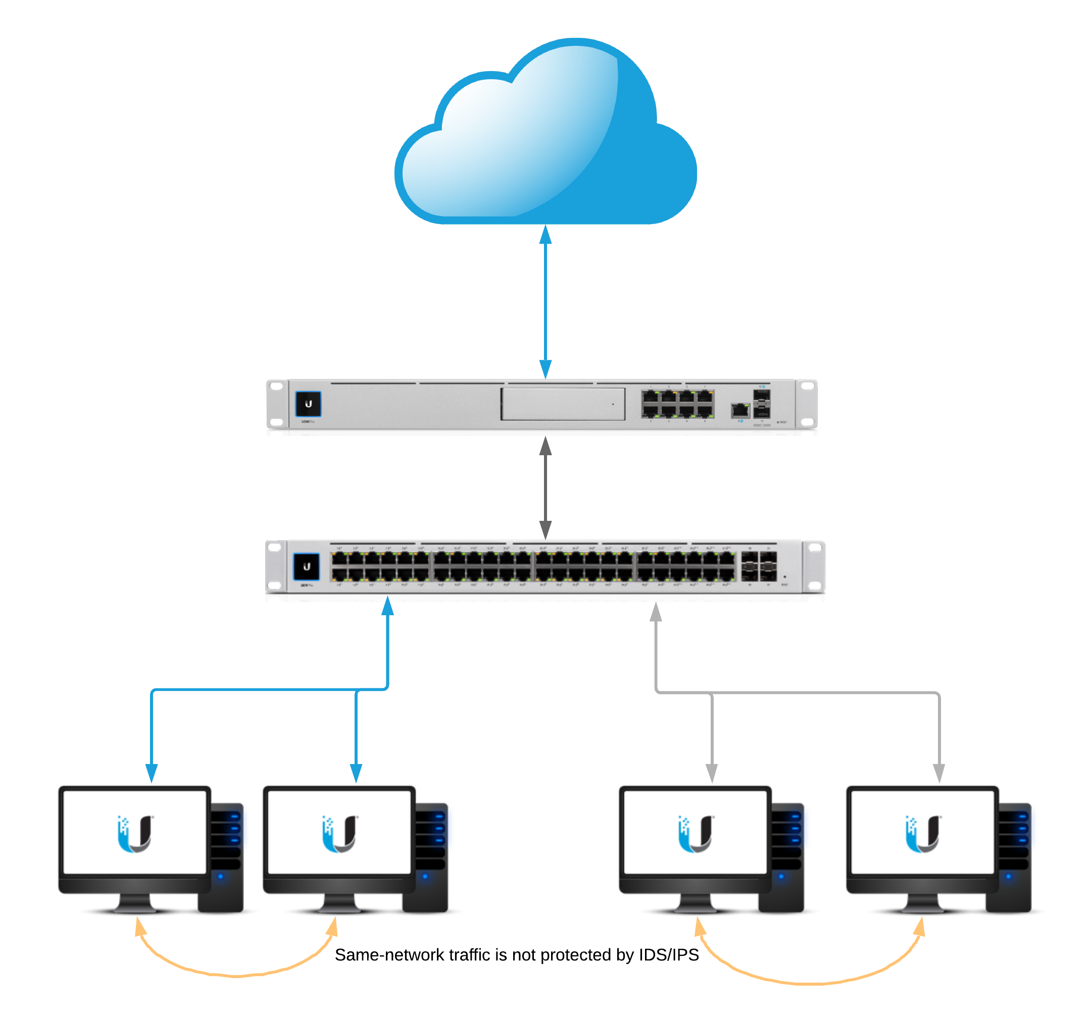
Network Diagram
Intrusion Detection and Prevention
To enable intrusion detection or intrusion prevention, navigate to the Settings > Security section of the UniFi Network application. ATTENTION:
Enabling IDS or IPS will affect the maximum throughput on inter-VLAN and egress traffic.
USG: 85 Mbps*
USG-Pro: 250 Mbps*
USG-XG: 1 Gbps*
Enabling Smart Queues or DPI on top of IPS/IDS will also incur a further throughput penalty to maximum throughput.
UniFi Dream Machine throughput: 850 Mbps*
UniFi Dream Machine Pro: 3.5Gbps*
*Values are rough estimates and can vary depending on configuration.
Threat Management Modes
Intrusion Detection System: When set will automatically detect, and alert, but will not block potentially malicious traffic.
Intrusion Prevention System: When set will automatically detect, alert, and block potentially malicious traffic.
Firewall Restrictions
These restrictions can be found under New Settings > Internet Security > Advanced.
Restrict Access to ToR: When enabled will block access to The Onion Router.
Restrict Access to Malicious IP Addresses: When enabled will block access to IP addresses or blocks of addresses that have been recognized as passing malicious traffic.
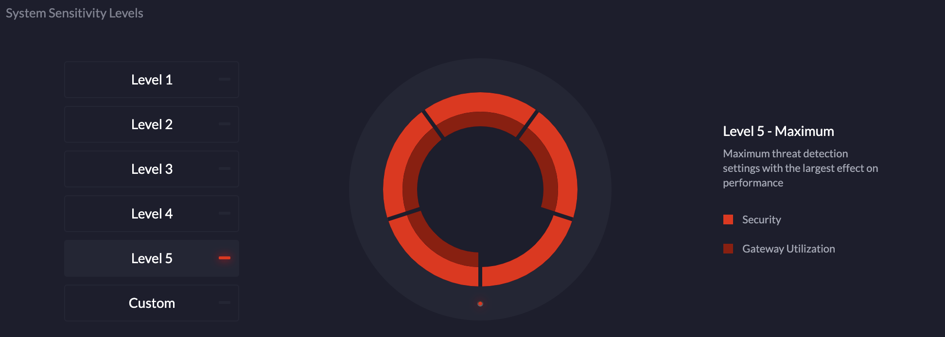
System Sensitivity Levels
The “system sensitivity levels” are pre-defined levels of security categories that will be loaded into the threat management daemon. Each level increase requires more memory and CPU usage. Additionally the “custom” level is utilized when manually selection categories.
Categories
ATTENTION:
Due to the amount of available memory on the USG3 and UDM a limited selection of categories can be enabled.
Click below to see a full list of categories.
Categories and Their Definitions
Click Here to Expand the IPS/IDS Categories Section
NOTE:The following configuration can be found in the Advanced tab of Internet Security.
Whitelisting
The Threat Management Allow List function of the IPS engine allows a UniFi Administrator to create a list of trusted IP’s. The traffic, depending on the direction selected, will not get blocked to or from the identified IPs.
Create a new allow list within Settings > Security > Internet Threat Management > Advanced.
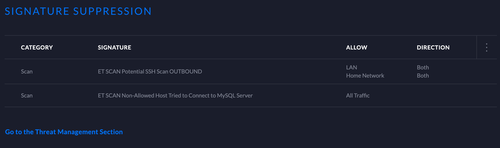
Signature Suppression
The signature suppression function of the IPS engine allows a UniFi Administrator to mute the alerting on certain signatures. This will also disable blocking on traffic matching the designated suppression rule.
Adding a signature suppression rule for all traffic will suppress the signature regardless of host IP.
Adding a signature suppression rule with packet tracking based on traffic direction and by single IP, defined UniFi Network, or subnet of choice.
GeoIP Filtering
NOTE:For GeoIP Filtering to work on the USG, hardware offloading must be enabled. When Threat Management is enabled (under Settings > Internet Security > Threat Management), hardware offloading is disabled. Only one of these two features can be enabled at a time on the USG.
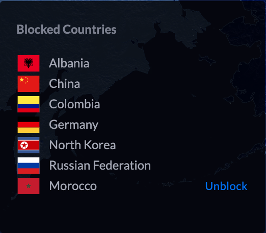
Blocking
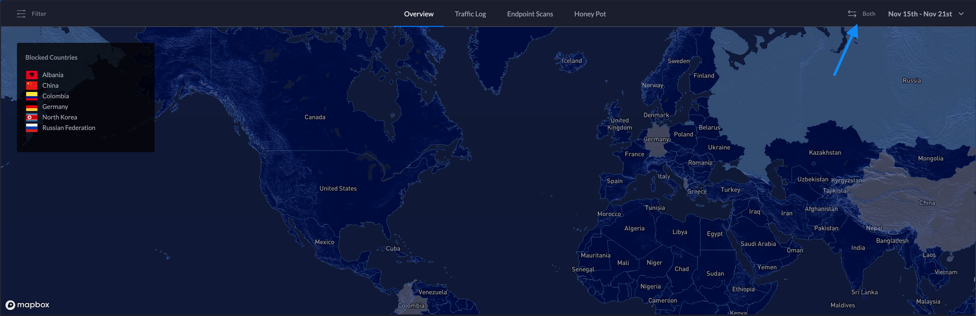
Blocking individual countries can be configured on the Threat Management Dashboard section. Blocking is as easy as navigating to the map, clicking on a country, and confirming by clicking “Block”.
Unblocking
Unblocking a country can be by performed on the Threat Management Dashboard by navigating to the left side of the map on the Overview tab. A list of blocked countries will be populated. Simply hover over the county that is to be unblocked and an “unblock” option will appear. Select “unblock” and the country will be taken off of the list.
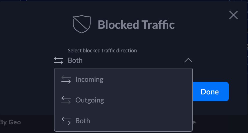
Traffic Direction
UniFi Network allows configuring the GeoIP filtering traffic direction. Follow the steps below:
1. Navigate to the top of the Threat Management Dashboard and select the direction.
2. Select the traffic direction.
3. Click Done.
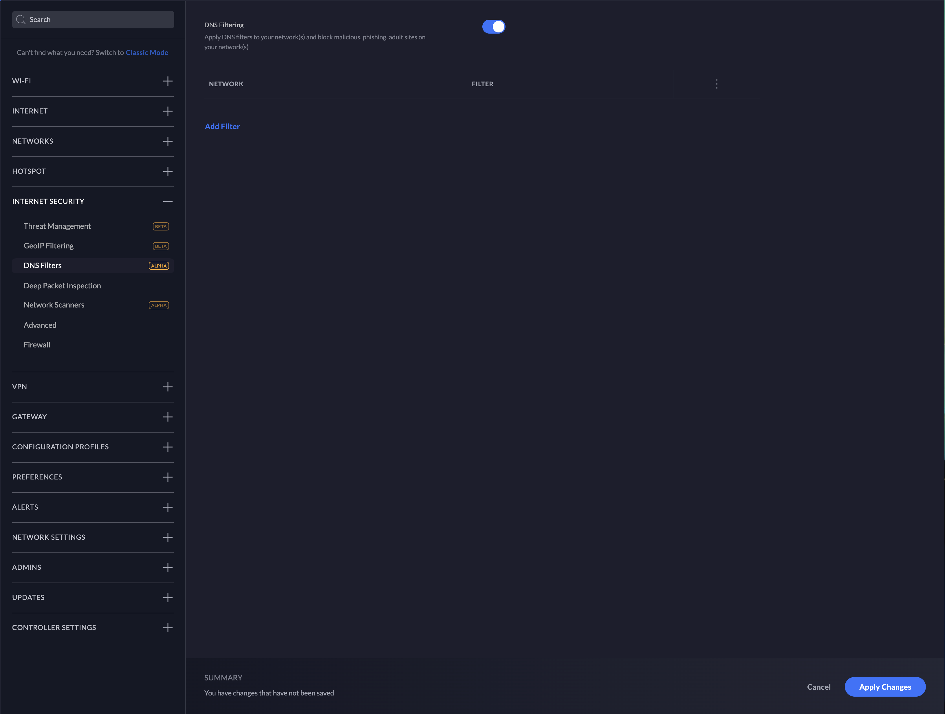
DNS Filters
ATTENTION:
DNS Filtering is only available on the UniFi Dream Machine.
Clients that use VPN, DNS-over-HTTPS, or DNS-over-TLS will have non-standard DNS requests that will not be seen by the UniFi Dream Machine.
The DNS Filter feature allows administrators to select levels of filtering per-network. This ensures that any DNS requests that go out from clients on configured LANs adhere to the filtering levels.
1. To configure DNS Filters, navigate to NewSettings > Internet Security > DNS Filters.
2. Enable DNS Filtering by clicking the slider button.
3. Select Add Filter.
4. Choose the desired level of filtering for the LAN.
5. Select which network this filter should apply to and confirm the selection.
6. DNS filtering will be enabled at this point.
Filter Levels
Security
Blocks access to phishing, spam, malware, and malicious domains. The database of malicious domains is updated hourly. Note that it does not block adult content.
Adult
Blocks access to all adult, pornographic and explicit sites. It does not block proxy or VPNs, nor mixed-content sites. Sites like Reddit are allowed. Google and Bing are set to the “Safe Mode”. Malicious and Phishing domains are blocked.
Family
Blocks access to all adult, pornographic and explicit sites. It also blocks proxy and VPN domains that are used to bypass the filters. Mixed content sites (like Reddit) are also blocked. Google, Bing, and Youtube are set to the Safe Mode. Malicious and Phishing domains are blocked.
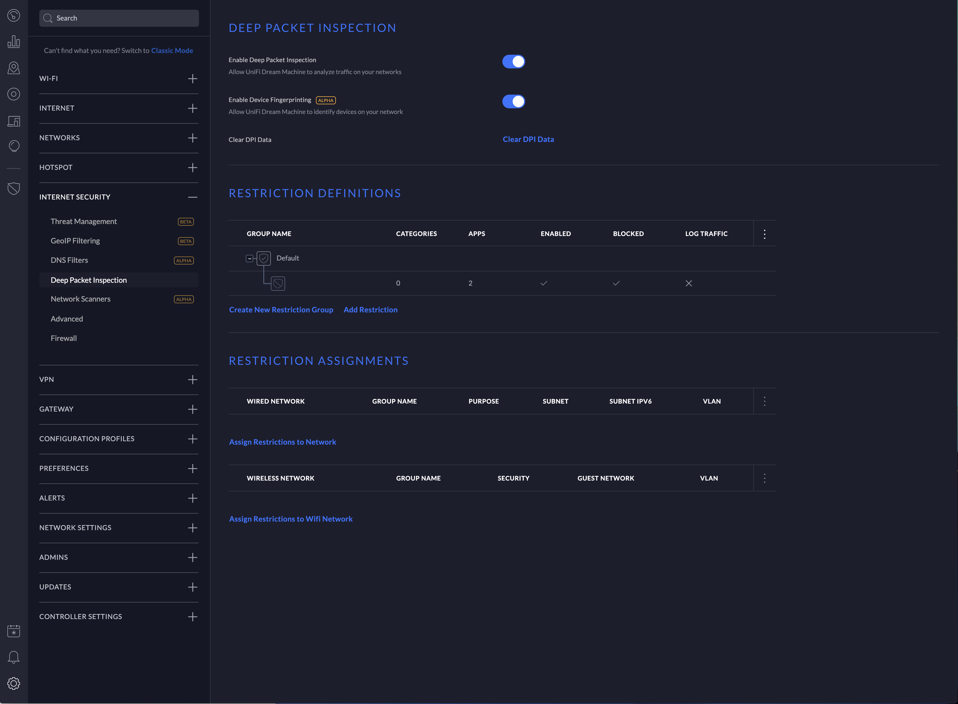
Deep Packet Inspection
To configure Deep Packet Inspection (DPI) navigate to NewSettings > Internet Security > Deep Packet Inspection.
NOTE: Device fingerprinting is not available on the UniFi Security Gateway.
DPI Restrictions
ATTENTION:DPI restrictions are limited to whole-category selections on the UniFi Security Gateway. This restriction is not applicable to the UniFi Dream Machine platform.
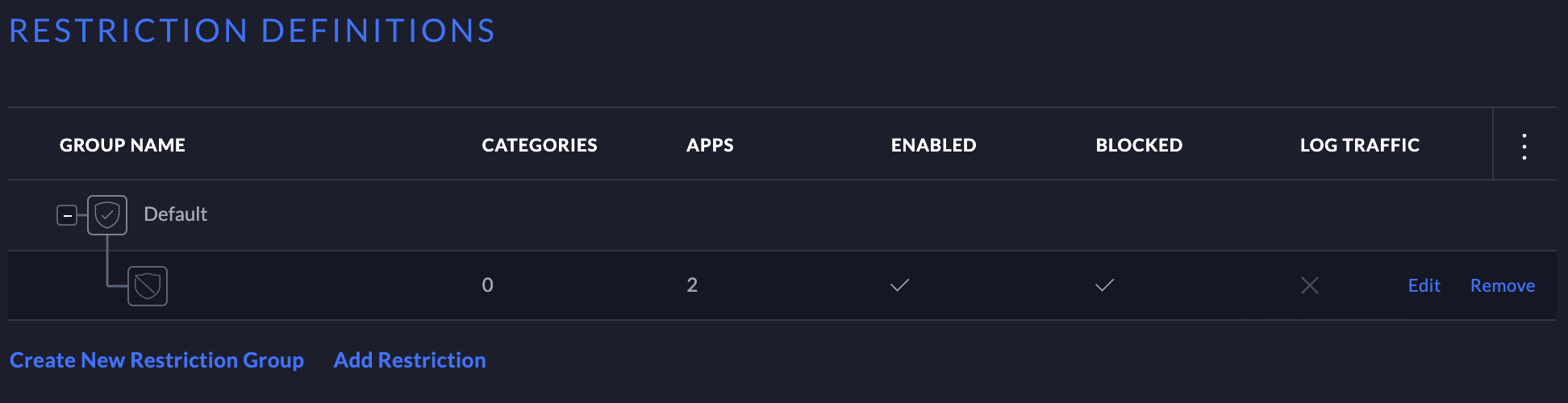
1. Click Add Restriction under “Restriction definitions”.
2. In the configuration side-panel select a restriction group to add the rules to.
3. Select a category to block.
4. Select an application from the category or select “All applications” to block the entire category.
5. Ensure that “Enable This Restriction” is selected.
6. Add the restriction group to a network in the “Restriction assignments” section. NOTE:A restriction definition can be applied to many networks. A restriction definition for each network is not required.
To manage the restriction definition, hover over the definition and selection either edit or remove.
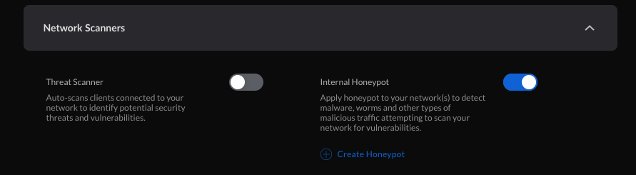
Configuring Network Scanners
ATTENTION:Network Scanners are only available on the UniFi Dream Machine.
Internal Honeypot
The “internal honeypot” feature is a passive detection system that listens for LAN clients attempting to gain access to unauthorized services or hosts. Clients that are potentially infected with worm or exfiltration type vulnerabilities are known to scan networks, infect other hosts, and potentially snoop for information on easy-to-access servers. The honeypot will report when hosts attempt to access the honeypot. Reports can be found on the Threat Management Dashboard.
To configure the internal honeypot follow the steps below:
1. Navigate to Settings > Security > Internet Threat Management > Network Scanners.
2. Enable the honeypot service by clicking the slider button.
3. Select “Create Honeypot”.
4. In the popup modal select the network and Honeypot IP.
5. Select “Create”.
Honeypot Services
The honeypot service listens on the following ports:
FTP – TCP Port 21
SSH – TCP Port 22
Telnet – TCP Port 23
SMTP – TCP Port 25
DNS – UDP Port 53
HTTP – TCP Port 80
POP3 – TCP Port 110
SMB – TCP Port 445
MSSQL – TCP Port 1433
Testing & Verification
Intrusion Detection/Prevention
Linux or macOS
Input:
curl -A "BlackSun" www.example.com
Expected alert result:
Threat Management Alert 1: A Network Trojan was Detected. Signature ET USER_AGENTS Suspicious User Agent (BlackSun). From: 192.168.1.172:55693, to:172.217.4.196:80, protocol: TCP
Windows
The DNS category must be enabled
Input:
nslookup blacklistthisdomain.com 8.8.8.8
Expected alert result:
Threat Management Alert 1: A Network Trojan was Detected. Signature ET DNS Reply Sinkhole - 106.187.96.49 blacklistthisdomain.com. From: 192.168.1.1:53, to: 192.168.1.182:61440, protocol: UDP
Internal Honeypot
A few examples of manually testing the internal honeypot service are below. The following commands may or may not prompt for login credentials. The alerts will appear in the Honeypot section of the Threat Management Dashboard a few minutes after attempting the testing.
Telnet:
telnet <honeypot_ip>
SSH:
ssh <honeypot_ip>
NOTE:Replace <honeypot_ip> with the honeypot IP configured in the UniFi Network application.
Privacy Statement
What information does the IPS/IDS engine send to the cloud?
1. When a UniFi Administrator enables IPS or IDS on the UniFi Network application a token is generated for the gateway. The information listed below is sent over a TLS 1.2 encrypted connection whenever there is an IPS/IDS signature match.
timestamp
interface
source IP
source port
destination IP
destination port
protocol
signature id
2. Every 120-seconds there is a keep-alive to the ips1.unifi-ai.com hostname. This connection is to ensure reliable delivery of the violation message. The keep-alive is a connection to our cloud using port 443 so it is not just an ICMP ping or DNS resolution but a complete 3-way handshake and SSL Key exchange.
What information is kept on our servers regarding IPS/IDS?
The data listed above is only temporarily stored in the IPS Cloud until the UniFi Network application downloads the information. After the information is downloaded by the application, the data is deleted from our cloud except for the attacker IP. The attacker IP information helps Ubiquiti maintain an up-to-date and effective attacker list which will improve Ubiquiti’s services to Ubiquiti customers around the world.
How is the information from alerts used by Ubiquiti?
Ubiquiti will use the alert information to improve its products and services, including generating lists of IP Reputation, Malicious IP addresses, Threat Intelligence and creating blacklists and new signatures for Ubiquiti devices. A sanitized version of IP addresses (Ex: 200.200.x.x) can also be displayed on Ubiquiti Public Threat Map to help the public community to see malicious traffic around the world.
This article will provide suggestions for troubleshooting and resolving issues with slow Wi-Fi speeds on your UniFi network, as well as better understand what Wi-Fi speeds to expect and how to optimize your Wi-Fi configuration.
One of the most common Wi-Fi performance concerns reported is slower than expected Wi-Fi speed. This is due to a number of factors:
Speed issues can result from a wide range of network limitations and problems, many of which have nothing to do with wireless.
Declined speed is easy to notice in typical network usage.
Internet speed tests are the most widely—and sometimes the only tool used to evaluate/benchmark network performance: and can be inconsistent and inaccurate.
ISPs and hardware vendors market products with peak theoretical performance that differ from real-life usage.
Measuring Wi-Fi Performance
When looking at Wi-Fi performance it is important to take a step back and consider how Wi-Fi is supposed to work. Wi-Fi offers the benefit of mobility, scalability, and convenience over wired networks at the expense of maximum throughput and stability. With respect to client performance, modern Wi-Fi is designed to allow clients to enjoy the benefits of not being tethered to a wired network while preventing any visible reduction in performance across its area of coverage.
Much of the concern about wireless throughput comes from a lack of understanding about how much bandwidth clients actually use. The difference between 300 Mbps and 500 Mbps may seem significant but the difference in performance would likely never be noticed through client use.
Here are estimated requirements of what throughput client devices need to use without declined performance (for more info see here):
UniFi’s products are designed and tested to ensure they can provide for this typical use for many clients simultaneously. Any Access Point (AP) currently being offered in the UniFi product line offers far greater potential throughput than any client application could realistically require.
If a UniFi Access Point fails to provide the speed that it is capable of, this is most often a result of environmental limitations or other bottlenecks in the deployment. UniFi provides many tools that can help users identify these factors and mitigate them with proper configuration.
Prerequisites
The rest of this article assumes that the following prerequisites have been met:
1. Eliminate any bottlenecks
Before working to improve your Wireless performance, it’s important to identify any bottlenecks outside of your Wireless network. A bottleneck is a point in a network infrastructure that limits performance everywhere else. Often poor Wi-Fi speed is incorrectly assumed to be a result of Wi-Fi hardware/config but actually is the result of a bottleneck upstream from the device. Here are some common examples of bottlenecks:
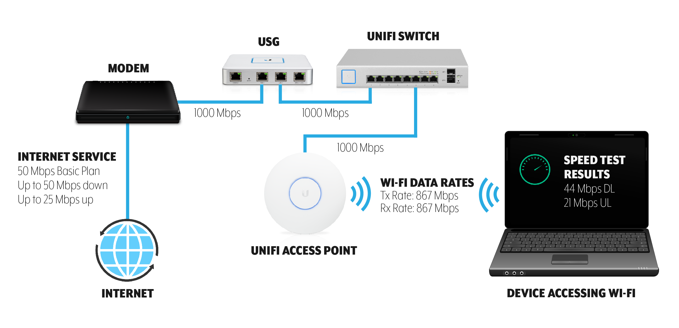
ISP Plan limits performance/speeds far beneath what Wi-Fi is capable of providing. For example, a plan might have a 100Mb/25Mb down/up bandwidth limit on service. Every UniFi device, including legacy devices, is capable of far exceeding this limit. See the image below.
Far too few APs for the number of clients/coverage requirements.
Old/faulty ethernet cables.
Outdated LAN hardware.
Outdated Wireless hardware.
Legacy client devices that don’t support 5GHz.
Too much noise on a single channel.
The following is an example of a common network bottleneck:
Diagram illustrating how Wi-Fi speed test results can be limited by ISP
An easy way to at least rule out any bottleneck is to plug a wired device into the secondary port on an AP and perform the same speed test you are using to test Wi-Fi performance and compare the results to each other. It is normal to see some diminished performance on wireless compared to wired speed tests, but make sure you at least know what your wired network is capable of providing to the AP.
2. Update your UniFi OS Console and UniFi Access Point (AP) Firmware to Current Version
Ubiquiti’s Firmware updates often include performance improvements: make sure that before testing the performance, you update your UniFi OS Console and your UniFi devices to the most current firmware available.
This section examines some of the most common issues that cause diminished speeds on UniFi Networks, as well as the steps that will solve them.
Channel Width
Channel width is the most common cause for poor speed test results after setting up UniFi, especially when being compared to a single wireless router the UniFi devices are replacing. Default UniFi config on 5GHz radio is optimized for large environments (40MHz channel width), while most standalone routers are optimized for use as the only AP in a home/office (80MHz).
To properly test the maximum speed of a UniFi AP, switch to 80 MHz. 80 MHz channels are capable of more than double the peak speed of 40 MHz channels.NOTE: These settings only apply to 5GHz. We do not recommend that channel width be increased from 20 MHz on 2.4GHz as this will often cause worse performance.
To change AP to use 80MHz channel width, go to Devices > Click on AP to open Properties Panel > Radios > RADIO 5G (11N/A/AC), Change Channel Width from VHT40 to VHT80, click Queue Changes, then Apply Changes.
Summary: If using a small number of APs, switch 5GHz channel width on APs to 80 MHz for greater peak throughput. In larger environments, note that 40 or 20 MHz channel width is recommended for performance but can limit peak throughput.
Interference/Channel Overlap
The single most potentially negative environmental factor for Wi-Fi performance and stability is wireless interference. Interference can come from external sources like other wireless networks, weather radar, etc. while internal interference can come from devices overlapping with each other on the same channel.
By default, UniFi Devices are set up with auto channel assignments, but this is something you will want to adjust for your deployment if there are concerns about speed/performance.
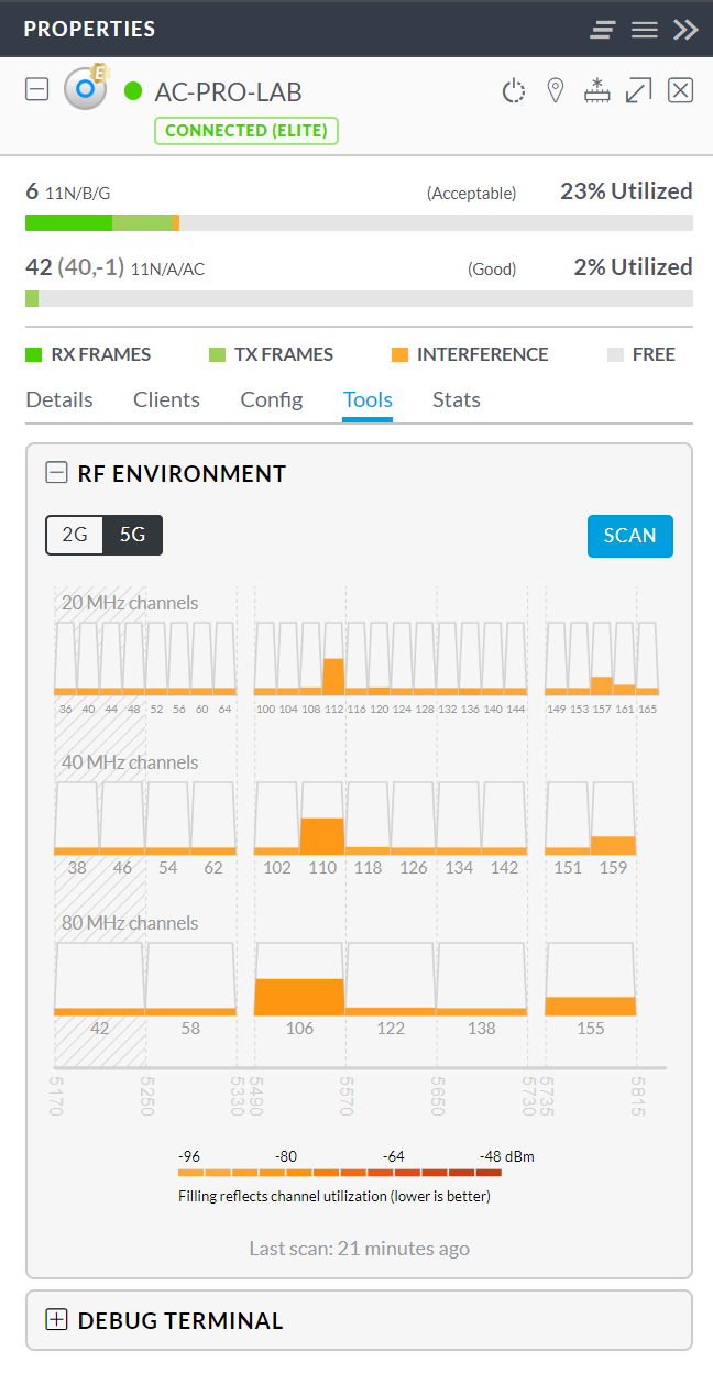
It is recommended that a full site survey be performed for high-density/high-priority Wi-Fi deployments. If that has not been done or the site doesn’t warrant it, the Network application can help you find a better channel assignment for your APs by performing an RF scan.
To do this, go to Devices > Click on AP to open PropertiesPanel > Tools > RF Environment and click Scan. User Tips:Running an RF Scan will disconnect any wireless clients currently connected to the AP. Do not run during peak hours if this is a concern. Suggested Channel Settings: 2.4GHz: Channel width: HT20 Chanel: 1/6/11 Choose one of these channels, an RF scan will help you choose the cleanest one.Transmit Power: Medium5GHz: Channel width: VHT40 Optional VHT80/VHT160 (It will increase speeds but might cause more interference.) Chanel: 36/44 | Optional (149/157) Choose one of these channels, an RF scan will help you choose the cleanest one. Avoid using DFS Channels unless you understand DFS logic. (DFS Alerts will cause interruptions) Transmit Power: Medium (High)You could also modify your DTIM Periods if you have more modern devices on the network. Settings > Wireless Network > SSID > 802.11 Rate And Beacon Controls DITM 2G Period: 3 DITM 5G Period: 3
This scan will take 5-10 minutes and will populate the 2.4GHz channels first and then 5 GHz channels will subsequently be updated.
Once your RF scan is finished, select 5G and you’ll see a list of channels arranged by channel width and how much each channel is being utilized. Select a channel that appears to have the least noise on it and assign your AP to this channel.
To do this go to Devices > Click AP to select it and open Properties Panel > Properties > Radios > RADIO 5G (11N/A/AC), and choose the desired channel.
If using multiple APs, make sure that each AP does not share the same channel as a nearby AP, and avoid having channels that are adjacent to each other as this can also cause interference.
Summary: Interference/channel overlap can cause performance to decline. To make sure speed test results are not being impacted by interference, make sure APs are assigned to the optimal channel and not sharing or adjacent to the channel of any nearby APs.
Signal Quality
Another factor that can strongly influence Wi-Fi speed is the signal quality between AP and client device. As clients get further away from an access point and the signal gets weaker, to ensure stability/offer the best possible performance, the AP will lower the rate of the data transfer to compensate.
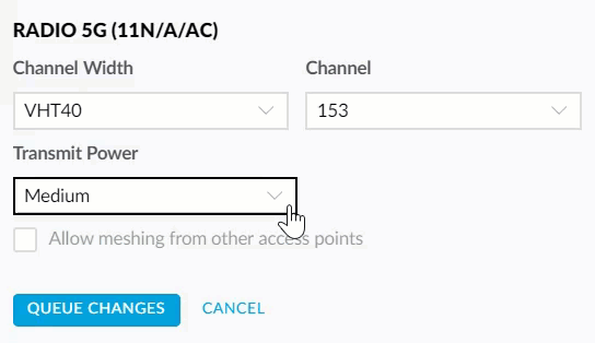
When testing peak throughput, be sure to be standing close enough to the AP without obstructions and make sure the client signal strength is close to the maximum of 99%. If your client devices consistently have poor signal strength on 5GHz try increasing Transmit Power on 5GHz.
To increase TX power on 5GHz, go to device configuration > Radios > Radio 5G (11N/A/AC), and only select “High” from the dropbox under Transmit Power. NOTE: Increasing transmit power on devices can have undesired effects, especially in a very high density environment. Consider starting on High or Auto and only reducing to Medium as needed on a per-AP basis.
Summary: When testing throughput make sure to consider the signal strength between the device and AP, you can find this under the Clients tab in the Network application. If the range on 5GHz is very low, consider increasing Transmit Power on the AP’s 5GHz radio.
Inconsistent/Inaccurate Speedtest Methods
Another cause for poor speed test performance is inconsistent or inaccurate data. When comparing across devices, make sure to use the same speed test method as different speed test apps can vary wildly.
While UniFi does include a speed test, the results are often far lower than reality, especially since UniFi’s available speed test servers are limited and results are very sensitive to the proximity of the speed test server. Try using a popular speed test app or website to test to check your UniFi results. Be sure to test multiple times and do not rely on assumptions or past data to inform your comparison.
If you wish to most accurately assess Wi-Fi speed alone and rule out other factors, try performing an iPerf test between a wired and wireless client/between two wireless clients. iPerf only measures bandwidth between two devices on your network. Note that iPerf can still be limited by the syntax you can use, the number of streams, packet size, etc. so make sure you understand what you’re doing before using iPerf.
Summary: Speedtest results are often inaccurate. Make sure to use consistent speed test methods when comparing between devices, wired vs. wireless, etc. Confirm/test using multiple platforms. UniFi speed tests are often less accurate than other more popular speed test apps.
Client-specific Issues & Limitations
When benchmarking Wi-Fi, it’s important to also compare across devices to ensure that the client itself isn’t limiting performance. Factors like client CPU utilization, network card driver, Wi-Fi specs, software, all can influence speed test results.
Make sure to test with multiple devices. To truly measure peak throughput you must test a device that matches the capabilities of the UniFi AP. For instance, if you are testing with a device check the manufacturer specifications to see how many streams the 5GHz antenna supports i.e. Apple iPhone 7 is 2×2, UAP-AC-PRO has 3×3 5GHz radio, thus this iPhone will limit peak throughput.
If a performance issue with Wi-Fi is isolated to one device, or multiple devices running the same software version, this will almost always point to a problem with the device/software. UniFi doesn’t change how it functions for each variety of client device. Try performing a web search to find other users experiencing similar issues with the same device on other vendor products.
Keep in mind that declined performance on a single device isn’t a sign of a malfunctioning AP. UniFi APs are backwards compatible with older client devices and the fact that devices are able to connect with their older hardware is a sign the AP is working as designed.
Summary: Test multiple client devices when benchmarking Wi-Fi performance. Client-specific issues are common but are largely unrelated to AP configuration/hardware.
Additional Steps
After reviewing each of the previous steps, if the issue does not appear to be resolved, check out this article for some further suggestions to troubleshoot wireless performance.
If you’d like to get suggestions from other UniFi administrators, feel free to post on our community.
For issues that point to an issue with UniFi devices/software with respect to wireless performance, feel free to reach out to UniFi support. Please note that the UniFi support team is not able to optimize networks for customers and will not be able to assist with performance issues that are cosmetic in nature or do not indicate an actual UniFi performance issue i.e. improving speed test results from 400 Mbps to 600 Mbps.