[German]As of October 17, 2022, Microsoft has released several unscheduled updates for Windows. These updates fix a connection problem that can occur with SSL and TLS connections. Affected by this problem are probably all Windows client and server. Below I have listed all available updates and also give some hints where problems occur without these updates.
Advertising
Out-of-band updates with TLS fix
Microsoft made a mistake with the last updates for Windows (preview updates from September, security updates from October). As a result, various problems with SSL and TLS connections can occur. Microsoft has therefore released some : out-of-band updates on October 17, 2022 to fix the problem.
The out-of-band updates KB5020439 and KB5020440 were added on October 18th. These updates are only available for download in the Microsoft Update Catalog and have to be installed manually (just search for the KB numbers). Details about these updates can be found in the linked KB articles.
So only Windows 11 22H2 is missing the corresponding fix update. EP writes here that this fix will be added with the upcoming update KB5018496. This is currently released in the Windows Insider program as a pre-release version in the Release Preview channel (see).
Problems fixed with the updates
People have asked in comments which applications are actually affected by the TLS bugs. I don’t have a complete list, but would like to give some hints below as to what has come to my attention as a fix. Thanks to blog readers for the pointers.
Advertising
Citrix connectivity issue
With the October 2022 updates, administrators found that Citrix clients could no longer communicate with Citrix netscalers. I had reported on this in the blog postCitrix connections broken after Windows update KB5018410 (October 2022) (TLS problem). Affected people who installed the above updates reported that this fixed the connection problem.
KB5020387 fixes TLS 1.3 problem on Windows 10
On Windows, there was also the issue that there TLS 1.3 implementation was buggy on Windows 10 (it only works in Windows 11). I had raised a conflict case in the blog post Bug: Outlook no longer connects to the mail server (October 2022). Microsoft suggested disabling TLS 1.3 via registry intervention as a workaround. In this comment, someone suggests uninstalling updates KB5018410 (Windows 10) and KB5018427 (Windows 11).
Blog reader Harvester asked here, whether TLS 1.3 works with Windows 10 after installing the special updates, and then followed up with the results of his own tests.
Self-reply after tests : Schannel is working properly after having applied KB5020387 on a LTSC 2021 IoT Enterprise image (21H2), where Schannel was previously broken (on build 19044.2130, from October 11 2022)
We initially guessed that the IoT Enterprise SKU wasn’t supporting TLS 1.3, but now we confirmed that we hit the bug mentioned in the post.
“Fun” fact : while it as initially reported that TLS 1.3 was available starting from Windows 10 1903, the Schannel documentation was changed recently, and now state that only Windows 11 and Server 2022 support TLS 1.3: Protocols in TLS/SSL (Schannel SSP)
VPN and WebEx Meetings App
Within this German comment blog reader Marten reported, that the WebEx Meetings App could no longer connect to the WebEx Server (OnPrem) via VPN. The issue has been fixed via update.
Quest Migration Manager for Exchange
On Twitter, enno0815de has sent the following tweet, which refers to my message about the out-of-band updates with TLS fix. It says, anyone planning a domain migration using Quest Migration Manager for Exchange should also install the updates. Otherwise, the account will be locked out for the migration.
In a follow up tweet he adds: By some circumstance the Atelia class (Quest component) is deleted from the registry. Without the TLS fix, you lock the user out of AD completely.
[German]Since Monday, October 17, 2022, many Metro stores worldwide have been struggling with severe IT problems. I had already suspected a cyber attack on the Metro Group in a post and I had reports from Austria, from France as well as comments from German Metro customers as well as employees. However, a cyber attack remained unconfirmed so far. Now Metro AG has confirmed such an attack to heise – and on its website.
Advertising
Metro Group with IT problems
I had already reported about the IT problems at Metro Group in the blog post Cyber attack on Metro AG or just a IT break down? Austria, France, German (and more countries?) affected. Since Monday, October 17, 2022, Metro wholesales stores have been struggling with massive IT problems. No invoices or daily passes could be issued and online orders had also disappeared, Metro customers reported. A blog reader had provided me with the following photo of a Metro notice board.
Notification about IT disruption at a Metro wholesale store
The suspicion of a cyber attack has not been confirmed by company spokespersons till today (October 21, 2022). But I have had reports from German blog readers, reporting IT issues since days and some people told me, it’s a cyber attack as a root cause.
Not only Austria and France are affected, but Metro AG worldwide. In Germany, too, the same problem has existed since last Monday. No more stock or prices can be updated or checked in the store. The checkout system is still working but also sluggishly, resulting in long lines. If you want to reserve something digitally, that doesn’t work either.
One reader noted that from what he observed, the IT problems have been going on since Friday afternoon (October 14, 2022). A reader informed me on Facebook that their email systems had delivered a 442 connection Failed-Error when communicating with the Metro mail system last Monday. By the afternoon of October 19, 2022, communication with the Metro Group email system was working again – so something is happening.
Advertising
Metro confirms cyber attack
First a speaker from Metro AG confired to German IT magazine heise a cyber attack on it’s IT systems. After searching the Metro AG site today, I finally found the following statement. It says (translated in English):
Metro cyber attack confirmation (addenum: here is an English version)
T-Security Incident at METRO
METRO/MAKRO is currently experiencing a partial IT infrastructure outage for several technical services. METRO’s IT team, together with external experts, immediately launched a thorough investigation to determine the cause of the service disruption. The latest results of the analysis confirm a cyber attack on METRO systems as the cause of the IT infrastructure outage. METRO AG has informed all relevant authorities about the incident and will of course cooperate with them in every possible way.
During the operation of METRO stores and the regular availability of services, disruptions and delays may occur. The teams in the stores have quickly set up offline systems to process payments. Online orders via the web app and online store are being processed, but there may be individual delays here as well.
We will continue to analyze and monitor the situation intensively and provide updates if necessary. METRO sincerely apologizes for any inconvenience this incident may cause to customers and business partners.
So they confirmed just a cyber attack, but stay tight lipped about the details. No information, whether it’s a ransomware infection nor about a possible attack vector.
Metro AG is a listed group of wholesale companies (for purchases in the gastronomy sector). Headquartered in Düsseldorf, the group employs more than 95,000 people in 681 stores worldwide, most of them in Germany. In Germany, the company mainly operates the Metro wholesale stores. Sales are 24.8 billion euros (2020).
Over 45,000 VMware ESXi servers inventoried by Lansweeper just reached end-of-life (EOL), with VMware no longer providing software and security updates unless companies purchase an extended support contract.
Lansweeper develops asset management and discovery software that allows customers to track what hardware and software they are running on their network.
As of October 15, 2022, VMware ESXi 6.5 and VMware ESXi 6.7 reached end-of-life and will only receive technical support but no security updates, putting the software at risk of vulnerabilities.
The company analyzed data from 6,000 customers and found 79,000 installed VMware ESXi servers.
Of those servers, 36.5% (28,835) run version 6.7.0, released in April 2018, and 21.3% (16,830) are on version 6.5.0, released in November 2016. In total, there are 45,654 VMware ESXi servers reaching End of Life as of today
The findings of Lansweeper are alarming because apart from the 57% that enter a period of elevated risk, there are also another 15.8% installations that run even older versions, ranging from 3.5.0 to 5.5.0, which reached EOL quite some time ago.
In summary, right now, only about one out of four ESXi servers (26.4%) inventoried by Lansweeper are still supported and will continue to receive regular security updates until April 02, 2025.
However, in reality, the number of VMware servers reaching EOL today, is likely far greater, as this report is based only on Lansweeper’s customers.
VMWare versions detected on net scans(Lansweeper)
The technical guidance for ESXi 6.5 and 6.7 will carry on until November 15, 2023, but this concerns implementation issues, not including security risk mitigation.
The only way to ensure you can continue to use older versions securely is to apply for the two-year extended support, which needs to be purchased separately. However, this does not include updates for third-party software packages.
For more details about EOL dates on all VMware software products, check out this webpage.
What does this mean?
When a software product reaches the end-of-life date, it stops receiving regular security updates. This means that admins should have already planned ahead and upgraded all deployments to a newer release.
While it’s not unlikely that VMware will still offer some critical security patches for these older versions, it’s not guaranteed and certainly won’t release patches for all new vulnerabilities that are discovered.
Once an unsupported ESXi server has carried on for long enough without patches, it will have accumulated so many security vulnerabilities that attackers would have multiple ways to breach it.
Due to ESXi hosting virtual machines, attacking the server can potentially cause severe and wide-scale disruption to business operations, which is why ransomware gangs are so focused on targeting it.
More recently, Mandiant discovered that hackers found a new method to establish persistence on VMware ESXi hypervisors that lets them control the server and hosted VMs without being detected.
All that said, ESXi already enjoys ample attention from threat actors, so running outdated and vulnerable versions of the software would no doubt be a terrible idea.
Port Trunking, also known as LACP (Link Aggregation Control Protocol), allows you to combine multiple LAN interfaces for increased bandwidth and load balancing for multiple clients. It also provides failover capabilities to maintain network connectivity if a network port fails.
802.3ad (Dynamic Link Aggregation) is the No.5 mode according to the IEEE 802.3ad specification. It uses a complex algorithm to aggregate adapters by speed and duplex settings to provide load balancing and fault tolerance but requires a switch that supports IEEE 802.3ad with LACP mode properly configured.
Note: Your switch must support 802.3ad. Note: A NAS with multiple LAN ports is required.
Follow these steps to set up your NAS.
Log into the NAS as an administrator. Go to “Main Menu” > “Network & Virtual Switch” > “Interfaces”. Click “Port Trunking”.
Click “Add” from the pop-up window.
Select the network interfaces to use and select 802.3ad for the Port Trunking Mode.
Click the settings button beside 802.3ad.
Select a HASH policy for 802.3ad: The default setting is “layer 2 (MAC)“. This is compatible with every switch but only offers load balancing by MAC address. We recommend using “Layer 2+3 (MAC+IP)” for greater performance but you will need to check that your switch supports it.
Click “Apply” to finish.
Test Results:
The test results of before and after Port Trunking is as follows.
A Gigabit Ethernet Network
One user downloading a large video file from the NAS:
One user uploading a large video file to the NAS:
Two users downloading a large video file from the NAS at the same time: The throughput of the NAS reaches 108~110 MB/s (downloading):
Two users upload a large video file to the NAS at the same time: The throughput of NAS reaches 102~104 MB/s (uploading):
Aggregating two Gigabit Ethernet Networks on the NAS
One user downloads a large video file from the NAS:
One user uploads a large video file to the NAS:
Two users download a large video file from the NAS at the same time: The throughput of NAS reaches 210~223 MB/s (downloading):
Two users upload a large video file to the NAS at the same time: The throughput of NAS reaches 200~210 MB/s (uploading):
As displayed by the test results, Port Trunking can increase bandwidth on a QNAP NAS . But please note the following:
Port Trunking cannot break the speed limit of a single Ethernet device, but it offers a sufficient amount of bandwidth for multiple users connecting at the same time. For example, if two 1Gb NICs are used for Port Trunking, the aggregated network bandwidth will be increased to 2Gb, but the network speed will remain 1Gb.
Available system resources and the maximum read/write speeds of the storage devices on the NAS will greatly influence the overall bandwidth.
A self-encrypting drive (SED) is a drive with encryption hardware built into the drive controller. SEDs automatically encrypt all data as it is written to the drive and decrypt all data as it is read from the drive. Data stored on SEDs are always fully encrypted by a data encryption key, which is stored on the drive’s hardware and cannot be accessed by the host operating system or unauthorized users. The encryption key can also be encrypted by a user-specified encryption password that allows the SED to be locked and unlocked.
Because encryption and decryption are handled by the drive, accessing data on SEDs does not require any extra CPU resources from the host device. Data on SEDs also become inaccessible if the SEDs are physically stolen or lost. For these reasons, SEDs are widely preferred for storing sensitive information.
You can use SEDs to create SED secure storage pools in QTS and QuTS hero, and SED secure static volumes in QTS. You can also use SEDs to create regular storage pools or volumes, but the self-encrypting function on the SEDs would remain deactivated.
Why Use SEDs?
Data storage security is an extremely important matter for many enterprises and organizations, especially when they store personal data such as credit card information and identity card numbers, or industry secrets such as product blueprints and intellectual property.
If a data leak occurs, the enterprise or organization can face serious consequences. Apart from sensitive information being exposed, a data leak can also result in customer and client damages, revenue loss, and legal penalties.
Because SEDs use hardware-based full disk encryption, both the encryption and decryption processes occur in the disk hardware. This separation from the host operating system makes hardware encryption more secure than software encryption. Moreover, unlike software encryption, hardware encryption does not require extra CPU resources. If a SED is physically stolen or lost, it becomes practically impossible to obtain intelligible information from the SED.
For these reasons, SEDs are often a specified data security requirement in bidding processes for government agencies, health care institutions, and financial and banking services.
SED Types
QNAP categorizes SED types according to the industry-standard specifications defined by the Trusted Computing Group (TCG). Supported SED types are listed in the following table.
To check the SED type of an installed SED, go to Storage & Snapshots > Storage > Disks/VJBOD and click a SED.
SED Type
Supported
TCG Opal
Yes
TCG Enterprise
Yes, in QTS 5.0.1 (or later) and QuTS hero h5.0.1 (or later)
SED Storage Creation
You can use SEDs to create SED secure storage pools in QTS and QuTS hero, and SED secure static volumes in QTS. For details, see the corresponding QNAP operating system user guide.
Action
Details
Create a SED secure storage pool in QTS
The latest version of the QTS User Guide is available at https://www.qnap.com/go/doc/qts/.You can find the relevant topic by searching “self-encrypting drives”.
Create a SED secure static volume in QTS
Create a SED secure storage pool in QuTS hero
The latest version of the QuTS hero User Guide is available at https://www.qnap.com/go/doc/quts-hero/.You can find the relevant topic by searching “self-encrypting drives”.
SED Management
SED Storage Pool and Static Volume Actions
To perform the following actions, go to Storage & Snapshots > Storage > Storage/Snapshots, select a SED pool or volume, click Manage, then select Actions > SED Settings.
Action
Description
Change SED Pool PasswordChange SED Volume Password
Change the encryption password.Warning:Remember this password. If you forget the password, the pool or volume will become inaccessible and all data will be unrecoverable.You can also enable Auto unlock on startup.This setting enables the system to automatically unlock and mount the SED pool or volume whenever the NAS starts, without requiring the user to enter the encryption passwordWarning:Enabling this setting can result in unauthorized data access if unauthorized personnel are able to physically access the NAS.Tip:In some earlier versions of QTS and QuTS hero, this setting is known as Save encryption key.
Lock
Lock the pool or volume. All volumes/shared folders, LUNs, snapshots, and data in the pool or volume will be inaccessible until it is unlocked.
Unlock
Unlock a locked SED pool or volume. All volumes/shared folders, LUNs, snapshots, and data in the pool or volume will become accessible.
Disable SED Security
Remove the encryption password and disable the ability to lock and unlock the pool or volume.
Enable SED Security
Add an encryption password and enable the ability to lock and unlock the pool or volume.
Removing a Locked SED Storage Pool or Static Volume
Go to Storage & Snapshots > Storage > Storage/Snapshots.
Select a locked SED storage pool or static volume.Note:Static volumes are only available in QTS.
Click Manage, and then click Remove.The Removal Wizard window opens.
Select a removal option.OptionDescriptionUnlock and remove pool, data, and saved keyThis option unlocks the SED disks in the storage pool or static volume, and then deletes all data. The storage pool or static volume is removed from the system.You must enter the encryption password.Remove pool without unlocking itThis option removes the storage pool or static volume without unlocking the disks. The SED disks cannot be used again until you perform one of the following actions:
Unlock the disks. Go to Disks/VJBOD, click Recover, and then select Attach and Recover Storage Pool.
Erase the disks using SED erase.
Click Apply.
The system removes the locked SED storage pool or static volume.
Migrating a SED Secure Storage Pool to a New NAS
The following requirements apply when migrating a storage pool to a new NAS.
The two NAS devices must both be running QTS, or both be running QuTS hero. Migration between QTS and QuTS hero is not possible.
The version of QTS or QuTS hero running on the new NAS must be the same or newer than the version running on the original NAS.
On the original NAS, go to Storage & Snapshots > Storage > Storage/Snapshots.
Select a SED secure storage pool.
Click Manage.The Storage Pool Management window opens.
Click Action, and then select Safely Detach Pool.A confirmation message appears.
Click Yes.The storage pool status changes to Safely Detaching…. After the system has finished detaching the pool, it disappears from Storage & Snapshots.
Remove the drives containing the storage pool from the NAS.
Install the drives in the new NAS.
On the new NAS, go to Storage & Snapshots > Storage > Disks/VJBOD .
Click Recover, and then select Attach and Recover Storage Pool.A confirmation message appears.
Enter the encryption password.You must enter this password if you are using self-encrypted drives (SEDs) with encryption activated.
Click Attach.The system scans the disks and detects the storage pool.
Click Apply.
The storage pool appears in Storage & Snapshots on the new NAS.
Erasing a Disk Using SED Erase
SED Erase erases all of the data on a locked or unlocked SED disk and removes the encryption password.
Go to Storage & Snapshots > Storage > Disks/VJBOD.
Select a SED disk.
Click Actions, and then select SED Erase.The SED Erase window opens.
Enter the disk’s Physical Security ID (PSID).Tip:The PSID can usually be found on the disk label.If you cannot find the PSID, contact the disk manufacturer.
Click Apply.
The system erases all data on the SED.
SED Status
To view the status of a SED, go to Storage & Snapshots > Storage > Disks/VJBOD and click an installed SED.
SED Status
Description
Uninitialized
The SED is uninitialized. Drive encryption is deactivated.
Unlocked
The SED is initialized and unlocked. Drive encryption is activated. Data on the SED is encrypted and accessible.
Locked
The SED is initialized and locked. Drive encryption is activated. Data on the SED is encrypted and inaccessible.
Blocked
The SED is blocked for security reasons. The drive cannot be initialized.Note:To unblock the SED, reinsert the disk or erase the disk using SED Erase. For details, see Erasing a Disk Using SED Erase.
Glossary
Gloss
Definition
Auto unlock on startup
Setting that allows the system to automatically unlock a SED secure storage pool or SED secure static volume after the NAS restarts
Encryption key
A unique, randomized cryptographic string physically stored within the hardware in self-encrypting drives (SEDs) for encrypting data written to the drive and decrypting data as it is read from the drive
Encryption password
A user-defined password for locking and unlocking a SED secure storage pool or static volume
PSID (Physical Secure ID)
A unique key usually labeled on a self-encrypting drive (SED) for resetting the drive to factory default
SED Erase
Storage & Snapshots function for erasing all data on a self-encrypting drive (SED) and removing the encryption password
Threat actors behind the relatively new Venus Ransomware are hacking into publicly-exposed Remote Desktop services to encrypt Windows devices.
Venus Ransomware appears to have begun operating in the middle of August 2022 and has since encrypted victims worldwide. However, there was another ransomware using the same encrypted file extension since 2021, but it is unclear if they are related.
BleepingComputer first learned of the ransomware from MalwareHunterTeam, who was contacted by security analyst linuxct looking for information on it.
Linuxct told BleepingComputer that the threat actors gained access to a victim’s corporate network through the Windows Remote Desktop protocol.
Another victim in the BleepingComputer forums also reported RDP being used for initial access to their network, even when using a non-standard port number for the service.
How Venus encrypts Windows devices
When executed, the Venus ransomware will attempt to terminate thirty-nine processes associated with database servers and Microsoft Office applications.
When encrypting files, the ransomware will append the .venus extension, as shown below. For example, a file called test.jpg would be encrypted and renamed test.jpg.venus.
Files encrypted by the Venus Ransomware Source: BleepingComputer
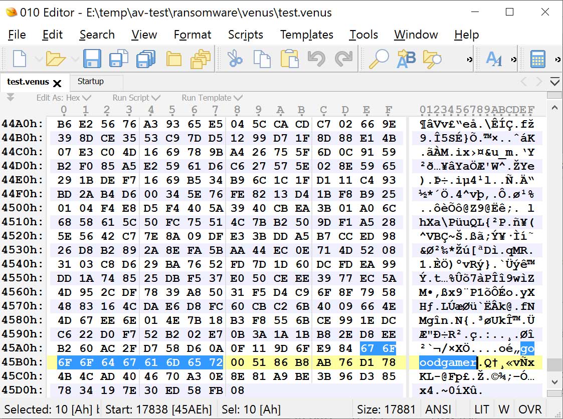
In each encrypted file, the ransomware will add a ‘goodgamer’ filemarker and other information to the end of the file. It is unclear what this additional information is at this time.
Goodgamer file marker in an encrypted file Source: BleepingComputer
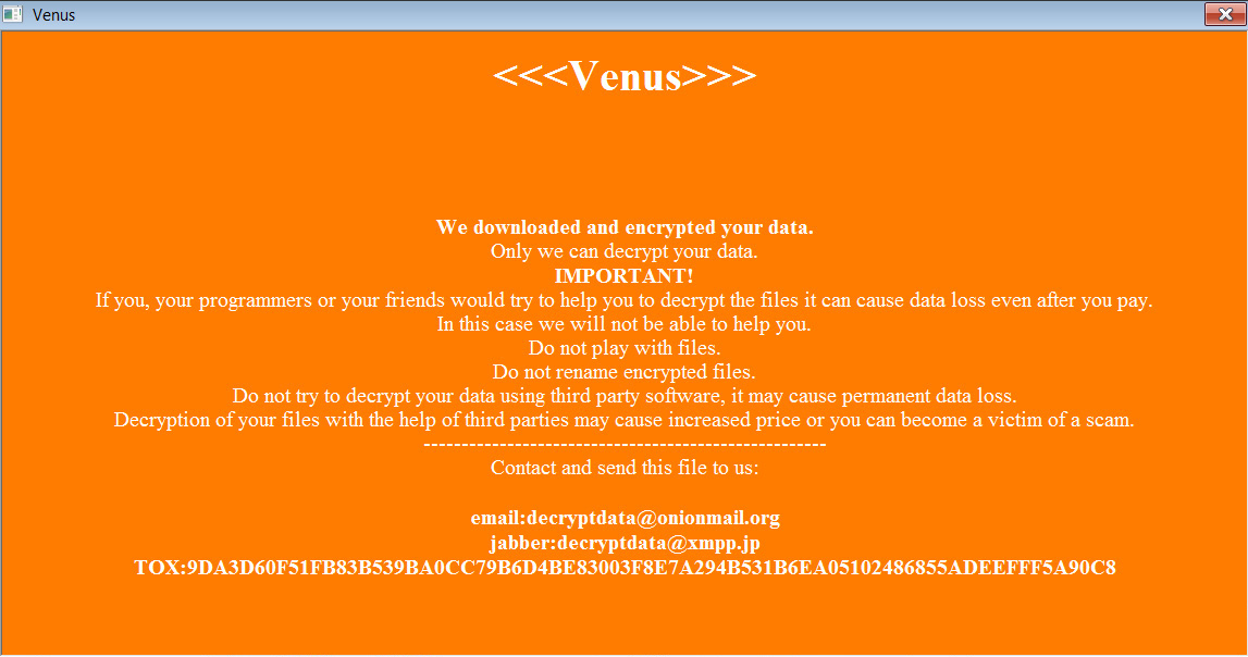
The ransomware will create an HTA ransom note in the %Temp% folder that will automatically be displayed when the ransomware is finished encrypting the device.
As you can see below, this ransomware calls itself “Venus” and shares a TOX address and email address that can be used to contact the attacker to negotiate a ransom payment. At the end of the ransom note is a base64 encoded blob, which is likely the encrypted decryption key.
At this time, the Venus ransomware is fairly active, with new submissions uploaded to ID Ransomware daily.
As the ransomware appears to be targeting publicly-exposed Remote Desktop services, even those running on non-standard TCP ports, it is vital to put these services behind a firewall.
Ideally, no Remote Desktop Services should be publicly exposed on the Internet and only be accessible via a VPN
This morning, the Wordfence Threat Intelligence team began tracking exploit attempts targeting CVE-2022-40684 on our network of over 4 million protected websites. CVE-2022-40684 is a critical authentication bypass vulnerability in the administrative interface of Fortinet’s FortiGate firewalls, FortiProxy web proxies, and FortiSwitch Manager, and is being actively exploited in the wild¹,².
At the time of publishing, we have recorded several exploit attempts and requests originating from the following IP addresses:
206.189.231.41
172.105.131.156
45.79.174.33
143.110.215.248
159.180.168.61
194.195.241.147
45.79.174.9
45.79.174.160
134.122.38.186
104.244.77.122
45.79.174.212
2.58.82.81
194.163.135.129
173.212.205.42
172.104.6.178
38.242.217.243
194.135.83.48
134.122.44.177
207.180.241.85
75.128.217.136
107.189.4.80
Most of the requests we have observed are GET requests presumably trying to determine whether a Fortinet appliance is in place:
GET /api/v2/cmdb/system/admin/admin HTTP/1.1
Accept-Encoding: gzip
User-Agent: Mozilla/5.0 (Windows NT 10.0; Win64; x64) AppleWebKit/537.36 (KHTML, like Gecko) Chrome/89.0.4389.114 Safari/537.36
Connection: close
X-Forwarded-Proto: https
X-Forwarded-Ssl: on
X-Forwarded-For: 75.128.217.136
Host: <redacted>
Content-Type: application/x-www-form-urlencoded
However, we also found that a number of these IPs are also sending out PUT requests matching the recently released proof of concept, referenced at the end of this advisory, which attempts to update the public SSH key of the admin user:
PUT /api/v2/cmdb/system/admin/admin HTTP/1.1
X-Forwarded-For: 172.104.6.178
Accept-Encoding: gzip
Forwarded: for=[127.0.0.1]:8000;by=[127.0.0.1]:9000;
Connection: close
User-Agent: Report Runner
Host: <redacted>
Content-Type: application/json
Content-Length: 610
While some requests are using a fake public key, which may indicate a benign vulnerability scanner, all of the requests using a valid public key are using the same public key, indicating that these requests are all the work of the same actor. An attacker able to update or add a valid public SSH key to a user’s account on a system can then typically gain access to that system as that user if they have the corresponding private key. In this case the attacker is attempting to add their own public key to the admin user’s account.
The SSH key has the following fingerprint: SHA256:GBl4Pytt+W2yEZ3zlOkAZkgtqmTPBcEZlqK4hoNOqBU dev@devs-MacBook-Pro.local (RSA)
All of the PUT exploit attempts we have seen are using the “Report Runner” User-Agent as this is a requirement of the exploit, though the exploit may also be viable with the User-Agent set to “Node.js”.
New IP Addresses attacking CVE-2022-40684 will appear on the Wordfence Intelligence IP Threat Feed in the “auth_bypass” category as the feed is updated every 60 minutes.
1. Fortinet released an advisory with additional information, including affected products and workarounds for users unable to patch. 2. Horizon3.ai initially discovered that the vulnerability was being exploited in the wild and released a proof of concept earlier today.
If you’re new to the world of virtualization, networking configuration can be one of the toughest concepts to grasp. Networking is also different in Hyper-V than in other hypervisors, so even those with years of experience can stumble a bit when meeting Hyper-V for the first time. This article will start by looking at the conceptual design of virtual networking in Hyper-V, configuration and then work through implementation best practices.
Networking Basics
Before beginning, it might be helpful to ensure that you have a solid grasp of the fundamentals of Ethernet and TCP/IP networking in general. Several articles that explain common aspects begin with this explanation of the OSI model.
The Hyper-V Virtual Switch
The single most important component of networking in Hyper-V is the virtual switch. There’s an in-depth article on the Hyper-V Virtual Switch on this blog, but for the sake of this article I’ll give you a basic introduction to the concept, within the bigger picture.
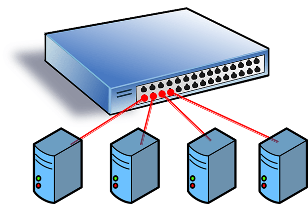
The key to understanding is realizing that it truly is a switch, just like a physical switch. It operates in layer 2 as the go-between for virtual switch ports. It directs packets to MAC addresses. It handles VLAN tagging. It can even perform some Quality of Service (QoS) tasks. It’s also responsible for isolating network traffic to the virtual adapter that is supposed to be receiving it. When visualized, the Hyper-V network switch should be thought of in the same way as a standard switch:
The next part of understanding the virtual switch is how it interacts with the host. To open that discussion, you must first become acquainted with the available types of virtual switches.
Virtual Switch Modes
There are three possible modes for the Hyper-V switch: private, internal, and public. Do not confuse these with IP addressing schemes or any other virtual networking configuration in a different technology.
Hyper-V’s Private Switch
The private switch allows communications among the virtual machines on its host and nothing else. Even the management operating system is not allowed to participate. This switch is purely logical and does not use any physical adapter in any way. “Private” in this sense is not related to private IP addressing. You can mentally think of this as a switch that has no ability to uplink to other switches.
Hyper-V’s Internal Switch
The internal switch is similar to the private switch with one exception: the management operating system can have a virtual adapter on this type of switch. This allows the management operating system to directly communicate with any virtual machines that also have virtual adapters on the same internal switch. Like the private switch, the internal switch does not have any relation to a physical adapter and therefore also cannot uplink to any another switch.
Hyper-V’s External Switch
The external switch type must be connected to a physical adapter. It allows communications between the physical network and the management operating system and the virtual adapters on virtual machines. Do not confuse this switch type with public IP addressing schemes or let its name suggest that it needs to be connected to an Internet-facing system. You can use the same private IP address range for the adapters on an external virtual switch that you’re using on the physical network it’s attached to. External in this usage means that it can connect to systems that are external to the Hyper-V host.
How to Conceptualize the External Virtual Switch
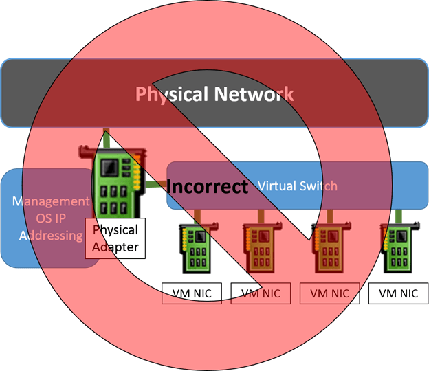
Part of what makes understanding the external virtual switch artificially difficult is the way that the related settings are worded. In the Hyper-V Manager GUI, it’s worded as Allow management operating system to share this network adapter. In PowerShell’s New-VMSwitch cmdlet, there’s an AllowManagementOS parameter which is no better, and its description — Specifies whether the parent partition (i.e. the management operating system) is to have access to the physical NIC bound to the virtual switch to be created. — makes it worse. What seems to happen far too often is that people read these and think of the virtual switch and the virtual adapters like this:
Unfortunately, this is not at all an accurate representation of Hyper-V’s virtual network stack. Once the virtual switch is bound to a physical adapter, that adapter is no longer used for anything else. TCP/IP, and most other items, are removed from it. The management operating system is quite simply unable to “share” it. If you attempt to bind anything else to the adapter, it’s quite probable that you’ll break the virtual switch.
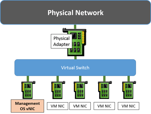
In truth, the management operating system is getting a virtual network adapter of its own. That’s what gets connected to the virtual switch. That adapter isn’t exactly like the adapters attached to the virtual machines; it’s not quite as feature-rich. However, it’s nothing at all like actually sharing the physical adapter in the way that the controls imply. A better term would be, “Connect the management operating system to the virtual switch”. That’s what the settings really do. The following image is a much more accurate depiction of what is happening:
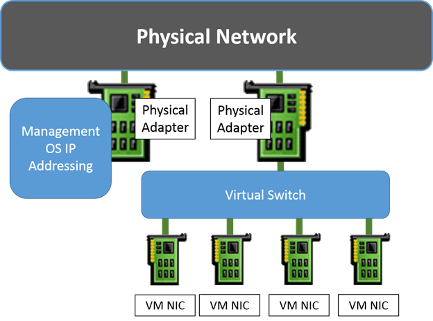
As you can see, the management operating system’s virtual adapter is treated the same way as that of the virtual machines’ adapters. Of course, you always have the option to take one or more physical adapters out of the virtual switch. Those will be used by the management operating system as normal. If you do that, then you don’t necessarily need to “share” the virtual switch’s adapter with the management operating system:
How to Use Physical NIC Teaming with the Hyper-V Virtual Switch
As of Windows Server 2012, network adapter teaming is now a native function of the Windows Server operating system. Teaming allows you combine two or more adapters into a single logical communications channel to distribute network traffic. Hyper-V Server can also team physical adapters.
When a teamed adapter is created, the individual adapters still appear in Windows but, in a fashion very similar to the virtual switch, can no longer be bound to anything except the teaming protocol. When the team is created, a new adapter is presented to the operating system. It would be correct to call this adapter “virtual”, since it doesn’t physically exist, but that can cause confusion with the virtual adapters used with the Hyper-V virtual switch. More common terms are team adapter or logical adapter, and sometimes the abbreviation tNIC is used.
Because teaming is not a central feature or requirement of Hyper-V, it won’t be discussed in detail here. Hyper-V does utilize native adapter teaming to great effect and, therefore, it should be used whenever possible. As a general rule, you should choose the Dynamic load balancing algorithm unless you have a clearly defined overriding need; it combines the best features of the Hyper-V Port and Transport Ports algorithms. As for whether or not to use the switch independent teaming mode or one of the switch dependent modes, that is a deeper discussion that involves balancing your goals against the capabilities of the hardware that is available to you. For a much deeper treatment of the subject of teaming with Hyper-V, consult the following articles in the Altaro blog:
How to Set Up a Native Team in Hyper-V Server 2012 – This article is mostly focused on the “how-to”. It was written too early to include a discussion of the new Dynamic algorithm. You can choose it as an alternative to the Hyper-V Port and hash algorithms.
Load-Balancing Algorithms – This article includes a complete discussion of all of the available load-balancing algorithms.
[thrive_leads id=’17165′]
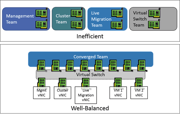
Hyper-V and Network Convergence
Network convergence simply means that multiple traffic types are combined in a single communications channel. To a certain degree, Hyper-V always does this since several virtual machines use the same virtual switch, therefore the same network hardware. However, that could all technically be classified under a single heading of “virtual machine traffic”, so it’s not quite convergence.
In the Hyper-V space, true convergence would include at least one other role and it would include at least two physical network adapters. The simplest way to achieve this is by teaming two or more adapters as talked about in the preceding section and then creating a virtual switch atop the team adapter. When the virtual switch is created, use the “share” option or PowerShell to create a virtual adapter for the management operating system as well. If that adapter is used for anything in the management operating system, then that is considered convergence. Other possible roles will be discussed later on.
While the most common convergence typically binds all adapters of the same speed into a single channel, that’s not a requirement. You may use one team for virtual machine traffic and another for the management operating system if you wish.
Hyper-V and Networking within a Cluster
Failover Clustering has its own special networking needs, and Hyper-V extends those requirements further. Each node begins with the same requirements as a standalone Hyper-V system: one management adapter and a virtual switch. A cluster adds the need for cluster-related traffic and Live Migration.
In versions prior to 2012, the only supported configuration required that all of these roles be separated into unique gigabit connections. With the enhancements introduced in 2012 and 2012 R2, these requirements are much more relaxed. There aren’t any published requirements with the new versions (although it could be argued that the requirements for 2008 R2 were never officially superseded, so they are technically still enforced). In practice, it’s been observed that it is absolutely necessary for there to be at least two unique cluster paths, but the rest can be adjusted up or down depending on your workloads.
The following describes each role and gives a brief description of its traffic:
Management: This role will carry all traffic for host-level backups and any host-related file sharing activities, such as accessing or copying ISO images from a remote system. During other periods, this role usually does not experience a heavy traffic load. The typical usage is for remote management traffic, such as RDP and WS-Man (PowerShell), which are very light.
Cluster Communications: Each node in the cluster continually communicates with all the other nodes in a mesh pattern to ensure that the cluster is still in operation. This operation is commonly known as the “heartbeat”, although network configuration information is also traded. Heartbeat traffic is typically very light, but it is extremely sensitive to latency. If it does not have a dedicated network, it can easily be drowned out by other operations, such as large file copies, which will cause nodes to lose quorum and fail over virtual machines even though nothing is technically wrong.
Cluster Shared Volumes: CSV traffic is not a unique role; it travels as part of standard cluster communications. When all is well, CSV traffic is fairly minimal, only passing CSV metadata information between the nodes. If a CSV goes into Redirected Access mode, then all traffic to and from that CSV will be handled by the owner node. If any other node needs to access that CSV, it will do so over a cluster network. The cluster will ensure that the normal cluster communications, such as heartbeat, are not sacrificed, but any struggles for bandwidths will cause virtual machines to perform poorly – and possibly crash. If your cluster does not use CSVs, then this traffic is not a concern.
Live Migration: Without constraints, a Live Migration operation will use up as much bandwidth as it can. The typical configuration provides a dedicated adapter for this role. With converged networking, the requirement is not as strict.
Virtual Machine traffic: VM traffic is arguably the most important in the cluster, but it also tends to not be excessively heavy. The traditional approach is to dedicate at least one adapter to the virtual switch.
While legacy builds simply separated these onto unique, dedicated gigabit pipes, you now have more options at your disposal.
SMB Enhancements for Cluster Communications
Cluster communications have always used the SMB protocol. The SMB protocol was upgraded substantially in 2012 and now has the ability to multichannel. This feature will auto-negotiate between the source and destination host and will automatically spread SMB traffic across all available adapters.
Whereas it used to be necessary to set networks for cluster communications and then modify metric assignments to guide traffic, the preferred approach in 2012 R2 is to simply designate two or more networks as cluster networks. The hosts will automatically balance traffic loads.
SMB Enhancements for Live Migration
If the cluster’s nodes are all set to use SMB for Live Migration, then it will take advantage of the same SMB enhancements that the standard cluster communications use. In this way, management traffic, cluster communications traffic, and Live Migration could all be run across only two distinct networks instead of two. This is potentially risky, especially if Redirected Access mode is triggered.
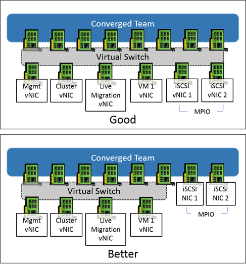
Converged Networking Benefits for Clustering
By using converged networks, you gain substantially more options with less hardware. SMB multichannel divides traffic across distinct networks – that is, unique subnets. By using converged networks, you can create more subnets than you have physical adapters.
This is especially handy for 10GbE adapters since few hosts will have more than two. It also has its place on 1GbE networks. You can simply combine all physical adapters into one single large team and create the same number of logical networks that you would have for a traditional role, but enable each of them for cluster communications and Live Migration. This way, SMB multichannel will be able to automatically load balance its needs. Remember that even with converged networking, it’s best to not combine all roles onto a single virtual or teamed adapter. SMB multichannel requires distinct subnets to perform its role and teaming balances some traffic according to the virtual adapter.
Quality of Service Benefits for Clustering
While the concern is rarely manifested, it is technically possible for one traffic type to fully consume a converged team. There are a number of QoS (Quality of Service) options available to prevent this from occurring. You can specifically limit SMB and/or Live Migration traffic and set maximums and minimums on virtual adapters.
Before you spend much time investigating these options, be aware that most deployments do not require this degree of control and will perform perfectly well with defaults. Hyper-V will automatically work to maintain a balance of traffic that does not completely drown out any particular virtual network adapter. Because the complexity of configuring QoS outweighs its benefits in the typical environment, this topic will not be investigated in this series. The most definitive work on the subject is available on TechNet.
How to Design Cluster Networks for Hyper-V
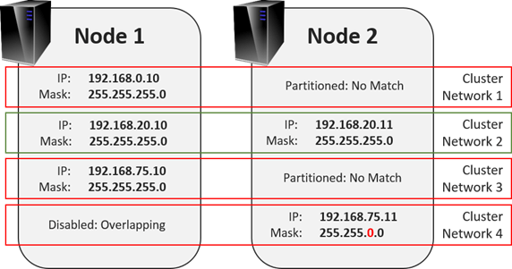
The one critical concept is that cluster networks are defined by TCP/IP subnet. The cluster service will detect every IP address and subnet mask on each node. From those, it will create a network for each unique subnet that it finds. If any node has more than one IP address in a subnet, the cluster service will use one and ignore the rest unless the first is removed. If the service finds networks that only some nodes have IP addresses for, the network will be marked as partitioned. A network will also be marked as partitioned if cluster communications are allowed but there are problems with inter-node traffic flow. The following diagram shows some sample networks and how clustering will detect them.
In the illustration, the only valid network is Cluster Network 2. The worst is Cluster Network 4. Due to the way the subnet is configured, it overlaps with all of the other networks. The cluster service will automatically lock the node 2 adapter with IP address 192.168.5.11 out of cluster communications and mark the network as None to indicate that it is disallowed for cluster communications.
Before building your cluster, determine the IP subnets that you’ll be using. It’s perfectly acceptable to create all-new networks if necessary. For cluster communications, the nodes will not intentionally communicate with anything other than the nodes in the same cluster. The minimum number of unique networks is two. One must be marked to allow client and cluster communications; this is the management network. One must be marked to allow cluster communications (client communications optional but not recommended). Further networks are optional, but will grant the cluster the opportunity to create additional TCP streams which can help with load-balancing across teamed adapters.
Hyper-V Networking Best Practices – Configuration in Practice
There isn’t any single “correct” way to configure networking in Hyper-V any more than there is a single “correct” way to configure a physical network. This section is going to work through a number of best practices and procedures to show you how things are done and provide guidance where possible. The best advice that anyone can give you is to not overthink it. Very few virtual machines will demand a great deal of networking bandwidth.
There are a few best practices to help you make some basic configuration decisions:
A converged network results in the best overall bandwidth distribution. It is extremely rare to have any situation in which a single network role will be utilizing an entire gigabit connection constantly. By dedicating one or more adapters to a single role, you prevent any other role from using that adapter, even when its owning role is idle.
A single TCP/IP stream can only use a single physical link. One of the most confusing things about teaming that new-comers face is that combining multiple links into a single team does not automatically mean that all traffic will automatically use all available links. It means that different communications streams will be balanced across available. Or, to make that more clear, you need at least four different communications streams to fully utilize four adapters in a team.
Avoid using iSCSI or SMB 3 directly with teaming. It is supported for both, but it is less efficient than using MPIO (for iSCSI) or SMB multichannel. It is supported to have multiple virtual network adapters on a team that are configured for iSCSI or SMB multichannel. However, you will always get the best performance for network storage by using unteamed adapters that are not bound to a virtual switch. This article explains how to configure MPIO.
If iSCSI and/or SMB connections are made through virtual adapters on a converged team, they will establish only one connection per unique IP address. Create multiple virtual adapters in order to enable MPIO and/or SMB multichannel.
For Failover Clustering, plan in advance what IP range you want to use for each role. For example:
Management: 192.168.10.0/24
Cluster communications/CSV: 192.168.15.0/24
Live Migration: 192.168.20.0/24
SMB network 1: 192.168.30.0/24
SMB network 2: 192.168.31.0/24
The only adapter in the management operating system that should have a default gateway is the management adapter. Assigning default gateways to other adapters will cause the system unnecessary difficulty when choosing outbound connections.
If cluster nodes have adapters that will only be used to communicate with back-end storage (iSCSI or SMB), exclude their networks from participating in cluster communications.
Only the management adapter should register itself in DNS.
Except for the one created by checking Allow the management operating system to share this network adapter, you cannot use the GUI to create virtual network adapters for the management operating system’s use.
You cannot use the GUI to establish a QoS policy for the virtual switch. The only time this policy can be selected is during switch creation.
If desired, virtual machines can have their IP addresses in the same range as any of the cluster roles. Failover Clustering does not see the ranges in use by virtual machines and will not collide with them.
The management operating system will allow you to team network adapters with different feature sets and even different speeds, but it is highly recommended that you not do this. Different features can result in odd behaviors as communication are load balanced. The system balances loads in round-robin fashion, not based on adapter characteristics (for instance, it will not prioritize a 10GbE link over a 1GbE link).
Networking QoS only applies to outbound communications. Inbound traffic will flow as quickly as it is delivered and can be processed.
10GbE links have the ability to outpace the processing capabilities of the virtual switch. A single virtual adapter or communications stream may top out at speeds as low as 3.5 Gbps, depending upon the processing power of the CPU. Balanced loads will be able to consume the entire 10GbE link, especially when offloading technologies, primarily VMQ, are in place and functional.
When teaming, choose the Dynamic load balancing algorithm unless you have a definite, verifiable reason not to. Do not prefer the Hyper-V Port mode simply based on its name; Dynamic combines the best aspects of the Hyper-V Port and Hash modes.
You can use iSCSI on a virtual machine’s virtual adapter(s) to connect it/them directly to network storage. You will have better performance and access to more features by connecting from the host and exposing storage to the guests through a VHDX. Virtual machines can have multiple network adapters, which enables you to connect the same virtual machine to different VLANs and subnets.
Avoid the creation of multiple virtual switches. Some other hypervisors require the administrator to create multiple virtual switches and attach them to the same hardware. Hyper-V allows only a single virtual switch per physical adapter or team. Likewise, it is not advisable to segregate physical adapters, whether standalone or in separate teams, for the purpose of hosting multiple virtual switches. It is more efficient to combine them into a single large team. The most common exception to this guideline is in situations where physical isolation of networks is required.
If your system is running a GUI edition of Windows Server, you can configure TCP/IP for all adapters using the traditional graphical tools. For all versions, you can also use sconfig.cmd for a guided process. This section shows how to perform these tasks using PowerShell. To keep the material as concise as possible, not all possible options will be shown. Refer to the introductory PowerShell article for assistance on using discovering the capabilities of cmdlets using Get-Help and other tools.
See Adapter Status (and Names to Use in Other Cmdlets)
Get-NetAdapter
Rename a Physical or Team Adapter
Rename-NetAdapter Name CurrentName NewName NewName
One final option that you may wish to consider is setting Jumbo Frames on your virtual adapters. A Jumbo Frame is any TCP/IP packet that exceeds the base size of 1514 bytes. It’s most commonly used for iSCSI connections, but can also help a bit with SMB 3 and Live Migration traffic. It’s not useful at all for traffic crossing the Internet and most regular LAN traffic doesn’t benefit much from it either. If you’d like to use it, the following post explains it in detail: https://www.altaro.com/hyper-v/how-to-adjust-mtu-jumbo-frames-on-hyper-v-and-windows-server-2012/. That particular article was written for 2012. The virtual switch in 2012 R2 has Jumbo Frames enabled by default, so you only need to follow the portions that explain how to set it on your physical and virtual adapters.
Configuring Virtual Switches and Virtual Adapters
All of the graphical tools for creating a virtual switch and setting up a single virtual adapter for the management operating system were covered in this previous article in the series. You cannot use the graphical tools to create any further virtual adapters for use by the management operating system. You also must use PowerShell to create your virtual switch if you want to control its QoS policy. The following PowerShell commands deal with the virtual switch and its adapters.
There are several things to note about this particular cmdlet:
The “InterfaceAlias” parameter shown above is actually an alias for “NetAdapterName”. The alias was chosen here because it aligns with the parameter name and output of Get-NetAdapter.
The cmdlet was typed with “vSwitch” as the virtual switch’s name, but you’re allowed to use anything you like. If your chosen name has a space in it, you must enclose it in single or double quotes.
If you do not specify the “AllowManagementOS” parameter or if you set it to true, it will automatically create a virtual adapter for the management operating system with the same name as the virtual switch. Skipping this automatic creation gives you greater control over creating and setting your own virtual adapters.
If you do not wish to enable SR-IOV on your virtual switch, it is not necessary to specify that parameter at all. It is shown here as a reminder that if you’re going to set it, you must set it when the switch is created. You cannot change this later.
The help documentation for Get-VMSwitch indicates that the default for “MinimumBandwidthMode” is “Weight”. This is incorrect. The default mode is “Absolute”. As with SR-IOV support, you cannot modify this setting after the switch is created.
Create a Private Virtual Switch
New-VMSwitch Name Isolated SwitchType Private MinimumBandwidthMode Weight
Many of the notes from the creation of the external switch apply here as well. The “EnableIOV” switch is not applicable to a private or internal switch at all. The “AllowManagementOS” switch is redundant: if the switch type is “Private” then no virtual adapter is created; if the switch type is “Internal”, then one is created. Adding one virtual adapter to the management OS on a Private switch will convert it to internal; removing all management OS virtual adapters from an Internal switch will make it Private.
Permanently Remove a Virtual Switch
Remove-VMSwitch Name vSwitch
This operation is permanent. The entire switch and all of its settings are lost. All virtual adapters in the management operating system on this switch are permanently lost. Virtual adapters in virtual machines connected to this switch are disconnected.
Add a Virtual Adapter to the Management OS
Add-VMNetworkAdapter ManagementOS SwitchName vSwitch Name 'New vAdapter'
The first thing to note is that, for some reason, this cmdlet uses “Add” instead of the normal “New” verb for creating a new object. Be aware that this new adapter will show up in Get-NetAdapter entries as vEthernet (New vAdapter) and that is the name that you’ll use for all such non-Hyper-V cmdlets. Use the same cmdlets from the previous section to configure
Retrieve a List of Virtual Adapters in the Management OS
Get-VMNetworkAdapter –ManagementOS
Rename a Virtual Adapter in the Management OS
Rename-VMNetworkAdapter ManagementOS Name CurrentName NewName NewName
How to Set VLAN Information for Hyper-V Virtual Adapters
Adapters for the management operating system and virtual machines can be assigned to VLANs. When this occurs, the Hyper-V virtual switch will handle the 802.1q tagging process for communications across the virtual switches and for packets to and from physical switches. As shown in the article on Virtual Machine settings, you can use Hyper-V Manager to change the VLAN for any of the adapters attached to virtual machines. You can only use PowerShell to change the VLAN for virtual adapters in the management operating system.
Retrieve the VLAN Assignments for All Virtual Adapters on the Host
GetVMNetworkAdapterVlan
You can use the “ManagementOS” parameter to see only adapters in the management operating system. You can use the “VMName” parameter with an asterisk to see only adapters attached to virtual machines.
Set the VLAN for a Virtual Adapter in the Management Operating System
Remove VLAN Tagging from all of a Virtual Machine’s Adapters
Set-VMNetworkAdapterVlan -VMName svtest –Untagged
If a virtual machine has more than one virtual adapter and you’d like to operate on it separately, that might require a bit more work. When the GUI is used to create virtual adapters for a virtual machine, they are always named Network Adapter, even if there are several. So, you’ll have to use PowerShell to rename them as they are created or you won’t be able to use the “VMNetworkAdapterName” to distinguish them. Instead, you can use Get-VMNetworkAdapter to locate other distinguishing features and pipe the output to cmdlets that accept VMNetworkAdapter objects. For example, you want to change the VLAN of only one adapter attached to the virtual machine named “svtest”. By using the tools inside the guest operating system, you’ve determined that the MAC address of the adapter you want to change is “00-15-5D-19-0A-24”. With the MAC address, you can change the VLAN of only that adapter by using the following PowerShell construct:
It is possible to use PowerShell to configure networking for your Failover Cluster, but it’s very inelegant with the current status of those cmdlets. At this time, they are not well-configured, so you must directly manipulate object property values and registry settings in fashions that are risky and error-prone. It is much preferred that you use Failover Cluster Manager to make these settings as explained in this article earlier on in the series.
Continue Exploring Networking
There’s a lot to digest in Hyper-V virtual networking. What you’ve seen so far truly is only the fundamentals. For a relatively simplistic deployment with no more than a few dozen virtual machines, you might not ever need any more information. As densities start to climb, the need to more closely tune networking increases. With gigabit adapters, your best option is to scale out. 10GbE adapters allow you to overcome physical CPU limitations with a number of offloading techniques, chief among these being VMQ. Begin your research on that topic by starting with the definitive article series on the subject, VMQ Deep Dive.
Otherwise, your best next steps are to practice with the PowerShell cmdlets. For example, learn how to use Set-VMNetworkAdapter to modify virtual adapters in similar fashion to the procedures you saw in the earlier GUI articles. With a little effort, you’ll be able to change groups of adapters at once. Hyper-V’s networking may be multi-faceted and complicated, but the level of control granted to you is equally vast.
This is flagged when you have a short cache expiration for images, fonts, media, scripts, and stylesheets. Google fails the audit if the cache expiration is under 180 days (259200 minutes). This simply means you need to adjust your cache expiration for those files to 180 days or over.
In most cases, you will login to your hosting account and adjust the static cache expiry (or similar) to 180 days. However, this can be quite a long time that visitors won’t see an updated version of those files. If you change these files frequently, a longer cache lifespan may not be best and you may want to make it shorter (even if it’s flagged). Google warns you about this.
I’ll cover a few other ways to serve static assets with an efficient cache policy in WordPress specifically for Cloudflare, other CDNs, Google Analytics, WP Rocket, and third-party scripts.
Login to Cloudflare and go to Caching → Browser Cache TTL, then set it for “6 months.”
3. Other CDNs
Most other CDNs let you change the browser cache expiration.
For example, in BunnyCDN, go to Pullzone → Your Website → Cache → Browser Cache Expiration. In this case, there is no option for 180 days. You can either set it for 1 year or “match server cache expiration.” You’ll need to make sure your server uses the correct cache expiration.
4. WP Rocket
WP Rocket has documentation on how their browser caching works.
This code is automatically added to your .htaccess file when you activate WP Rocket. But you will notice the browser cache expiration for images, fonts, and other files is 4 months (about 2 months short of Google’s 180 day requirement). It means you’ll need to change it to 180 days.
# Expires headers (for better cache control)

ExpiresActive on
    ExpiresDefault                              "access plus 1 month"
    # cache.appcache needs re-requests in FF 3.6 (~Introducing HTML5)
    ExpiresByType text/cache-manifest           "access plus 0 seconds"
    # Your document html
    ExpiresByType text/html                     "access plus 0 seconds"
    # Data
    ExpiresByType text/xml                      "access plus 0 seconds"
    ExpiresByType application/xml               "access plus 0 seconds"
    ExpiresByType application/json              "access plus 0 seconds"
    # Feed
    ExpiresByType application/rss+xml           "access plus 1 hour"
    ExpiresByType application/atom+xml          "access plus 1 hour"
    # Favicon (cannot be renamed)
    ExpiresByType image/x-icon                  "access plus 1 week"
    # Media: images, video, audio
    ExpiresByType image/gif                     "access plus 4 months"
    ExpiresByType image/png                     "access plus 4 months"
    ExpiresByType image/jpeg                    "access plus 4 months"
    ExpiresByType image/webp                    "access plus 4 months"
    ExpiresByType video/ogg                     "access plus 4 months"
    ExpiresByType audio/ogg                     "access plus 4 months"
    ExpiresByType video/mp4                     "access plus 4 months"
    ExpiresByType video/webm                    "access plus 4 months"
    # HTC files  (css3pie)
    ExpiresByType text/x-component              "access plus 1 month"
    # Webfonts
    ExpiresByType font/ttf    "access plus 4 months"
    ExpiresByType font/otf    "access plus 4 months"
    ExpiresByType font/woff   "access plus 4 months"
    ExpiresByType font/woff2  "access plus 4 months"
    ExpiresByType image/svg+xml                 "access plus 1 month"
    ExpiresByType application/vnd.ms-fontobject "access plus 1 month"
    # CSS and JavaScript
    ExpiresByType text/css                      "access plus 1 year"
    ExpiresByType application/javascript        "access plus 1 year"
Edit your .htaccess (you can use Htaccess File Editor if you don’t know how). Change the expiration from 4 months to 180 days. You may only want to do this for file types being flagged.
WP Rocket also suggests to check with your host to make sure they don’t block WP Rocket’s rules and that Mod_expires is enabled.
5. LiteSpeed Cache
To serve statics assets with an efficient cache policy using LiteSpeed Cache, go to LiteSpeed Cache Settings > Browser. Enable browser cache and the browser cache TTL should be left as default (31557600 seconds). If you still see errors, check if your host or CDN is overriding this.
6. W3 Total Cache
If you need to serve static assets with an efficient cache policy in W3 Total Cache, go your Browser Cache settings and change the Expires header lifetime to at least 15552000s (180 days). Make sure the cache expiration in your hosting and CDN settings aren’t overriding this.
7. Google Analytics
Google Analytics can also cause errors when serving static assets with an efficient cache policy.
If Google Analytics is appearing in PageSpeed Insights for this recommendation, CAOS Analytics lets you host analytics locally and adjust the cookie expiration period. WP Rocket’s Google Tracking Addon hosts it locally but doesn’t give you other options for the tracking code.
Install the CAOS Analytics plugin.
Go to Settings → Optimize Google Analytics → Advanced Settings → Cookie Expiry Period.
Set it to 180 days.
I recommend checking out other features in the CAOS Analytics plugin. Using a minimal analytics tracking code and serving it from your CDN can be beneficial for WordPress speed.
8. Google Fonts
Just like you hosted Google Analytics locally to control the cache lifespan, you can do the same thing with Google Fonts.
But they need to be hosted locally on your server (not pulling from fonts.gtstatic.com). You can do this by downloading your fonts directly from the Google Fonts website (remember to be minimal with font families and weights), converting them to WOFF2 format using a tool like Transfonter, then adding them to your CSS. Alternatively, you can also try the the OMGF plugin.
Once fonts are hosting locally, follow step #4 to set the cache expiration to 180 days for fonts.
9. Third-Party Scripts
Third-party code isn’t hosted on your server, so you can’t optimize it.
Google Analytics and fonts are an exception since they can be hosted locally, and therefore, you can control the cache expiration. But serving static assets with an efficient cache policy is not possible for AdSense, YouTube, Google Maps, and other third-party scripts that you might be getting errors for. Although, there may be other ways to optimize them like delaying JavaScript.
10. Purge Files And Retest
Once you’re done changing your cache expiration, remember to purge files and retest your WordPress site. Ideally you’ll have 100% for serve static assets with an efficient cache policy.
Frequently Asked Questions
How do I serve static assets with an efficient cache policy in WordPress?
Change your browser cache expiration to 180 days (or 259200 minutes). This is typically done in your hosting account, cache plugin, or CDN.
How do I serve static assets with an efficient cache policy using WP Rocket?
Edit your. htaccess file and locate the browser cache expiration code added by WP Rocket. Change the expiration from 4 months to 6 months for files flagged in Lighthouse, which are usually images or fonts.
How do I serve static assets with an efficient cache policy using Cloudflare?
Login to Cloudflare and go to Caching > Browser Cache TTL and change it to 6 months.
How do I serve static assets with an efficient cache policy using W3 Total Cache?
In your W3 Total Cache settings, go to Browser Cache and change Expires header lifetime to 180 days (15552000 seconds). Check your server and CDN to make sure they’re not overriding this setting.
Fortinet recently patched a critical authentication bypass vulnerability in their FortiOS, FortiProxy, and FortiSwitchManager projects (CVE-2022-40684). This vulnerability gives an attacker the ability to login as an administrator on the affected system. To demonstrate the vulnerability in this writeup, we will be using FortiOS version 7.2.1
POC
Let’s examine the inner workings of this vulnerability. You can find our POC here. The vulnerability is used below to add an SSH key to the admin user, enabling an attacker to SSH into the effected system as admin.
FortiOS exposes a management web portal that allows a user configure the system. Additionally, a user can SSH into the system which exposes a locked down CLI interface. Our first step after familiarizing ourselves with the system was to diff the vulnerable firmware with the patched firmware.
Firmware Examination
We obtained a VMware zip file of the firmware which contained two vmdk files. First, we examined the vmdk files with virt-filesystems and mounted them with guestmount:
Interestingly, attempting to decompress the xz files fail with corruption errors:
$>xz --decompress *.xz
xz: bin.tar.xz: Compressed data is corrupt
xz: migadmin.tar.xz: Compressed data is corrupt
xz: node-scripts.tar.xz: Compressed data is corrupt
xz: usr.tar.xz: Compressed data is corrupt
Its unclear if this is an attempt at obfuscation, but we find a version of xz in the sbin folder of the firmware. We can’t run it as is, but we can patch its linker to point to our system linker to finally decompress the files:
$>xz --decompress *.xz
xz: bin.tar.xz: Compressed data is corrupt
xz: migadmin.tar.xz: Compressed data is corrupt
xz: node-scripts.tar.xz: Compressed data is corrupt
xz: usr.tar.xz: Compressed data is corrupt
$>find . -name xz
./sbin/xz
$>./sbin/xz --decompress *.xz
bash: ./sbin/xz: No such file or directory
$>file ./sbin/xz
./sbin/xz: ELF 64-bit LSB executable, x86-64, version 1 (SYSV), dynamically linked, interpreter /fortidev/lib64/ld-linux-x86-64.so.2, BuildID[sha1]=eef5d20a9f8760df951ed122a5faf4de86a7128a, for GNU/Linux 3.2.0, stripped
$>patchelf --set-interpreter /lib64/ld-linux-x86-64.so.2 sbin/xz
$>./sbin/xz --decompress *.xz
$>ls *.tar
bin.tar migadmin.tar node-scripts.tar usr.tar
Next, we untar the files and begin examining their contents. We find /bin contains a large collection of binaries, many of which are symlinks to /bin/init. The migadmin folder appears to contain the frontend web code for the administrative interface. The node-scripts folder appears to contain a NodeJs backend for the administrative interface. Lastly, the usr folder contains a libaries folder and an apache2 configuration folder.
The Patch
We apply the same steps to firmware version 7.2.2 to enable diffing of the filesystems. In the bin folder, we find the large init binary has changed and in the node-scripts folder we find the index.js file has changed:
index.js diff
This diff shows that the httpsd proxy handler explicitly sets the forwarded, x-forwarded-vdom, and x-forwarded-cert headers. This gives us a hint as to where to start looking for clues on how to exploit this vulnerability.
HTTPSD and Apache Handlers
After some searching, we discover that the init binary we mentioned earlier contains some strings matching the headers in the NodeJs diff. This init binary is rather large and appears to have a lot of functionality including Apache hooks and handlers for various management REST API endpoints. To aid in our research, we SSH’d into the system and enabled debug output for the httpsd process:
fortios_7_2_1 # diagnose debug enable
fortios_7_2_1 # diagnose debug application httpsd -1
Debug messages will be on for 5 minutes.
fortios_7_2_1 # diagnose debug cli 8
Debug messages will be on for 5 minutes.
While investigating the forwarded header, we find an apache access_check_ex hook that parses the header, extracts the for and by fields, and attaches them to the Apache request_rec structure. You can see that the for field allows us to set the client_ip field on the request record’s connection.
forwarded header parsing
Additionally, we see a log message that mentioned which handler is used for a particular request.
After searching for the handler string, we find an array of handlers in the init binary:
hander array
After investigating some of the handlers, we find that many of them make a call to a function we named api_check_access:
api_check_access
We were immediately drawn to api_check_access_for_trusted_source which first checks if the vdom socket option is trusted, but then falls through to a function we called is_trusted_ip_and_user_agent.
is_trusted_ip_and_user_agent
You can see that this function checks that the client_ip is “127.0.01” and that the User-Agent header matches the second parameter. This function gets called with two possible parameters: “Node.js” and “Report Runner”. The “Node.js” path seems to perform some additional validation, but using “Report Runner” allows us to bypass authentication and perform API requests!
Weaponization
The ability to make unauthenticated request to the the REST API is extremely powerful. However, we noticed that we could not add or change the password for the admin user. To get around this we updated the admin users SSH-keys to allow us to SSH to the target as admin. See our original announcement.
Summary
To wrap things up here is an overview of the necessary conditions of a request for exploiting this vulnerabilty:
Using the Fowarded header an attacker is able to set the client_ip to “127.0.0.1”.
The “trusted access” authentication check verifies that the client_ip is “127.0.0.1” and the User-Agent is “Report Runner” both of which are under attacker control.
Any HTTP requests to the management interface of the system that match the conditions above should be cause for concern. An attacker can use this vulnerability to do just about anything they want to the vulnerable system. This includes changing network configurations, adding new users, and initiating packet captures. Note that this is not the only way to exploit this vulnerability and there may be other sets of conditions that work. For instance, a modified version of this exploit uses the User-Agent “Node.js”. This exploit seems to follow a trend among recently discovered enterprise software vulnerabilities where HTTP headers are improperly validated or overly trusted. We have seen this in recent F5 and VMware vulnerabilities.


.png)


 A confirmation message appears.
 If you cannot find the PSID, contact the disk manufacturer.
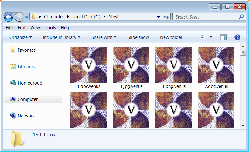


