Amazon AWS EC2 Create AMI Windows Image

Would you like to learn how to create an Amazon AMI Windows image? In this tutorial, we are going to show you how to create a Windows image from a virtual machine and how to deploy a new EC2 virtual machine using an AMI image.

Amazon AWS Playlist:

On this page, we offer quick access to a list of videos related to Amazon AWS.

Don’t forget to subscribe to our youtube channel named FKIT.

Amazon AWS Related Tutorial:

On this page, we offer quick access to a list of tutorials related to Amazon AWS.

Tutorial – How to Create an AWS EC2 Windows

On the EC2 Dashboard, access the Instances menu and click on the Instances option.
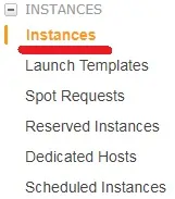
aws ec2 instances

On the EC2 Instance screen, click on the Launch Instance button.

aws ec2 launch instance

Now, it is time to select the desired Operational system image.

On the list presented, locate and select the Windows image.

ec2 windows 2012

As the second step, you will have to select the type of virtual machine that will run the Windows.

Basically, you will select the number of processors and the amount of RAM that you want.

aws ec2 vm type

If you do not want to specify the amount of hard disk available to this virtual machine, click on the Review and Launch button.

If you want to specify the amount of hard disk available to this virtual machine, click on the Configure instance detail button.

On the summary screen, click on the Launch button.

aws ec2 launch

Select the Key pair authorized to connect to the new virtual machine and click on the Launch Instances.

In our example, the key pair named TEST was selected.
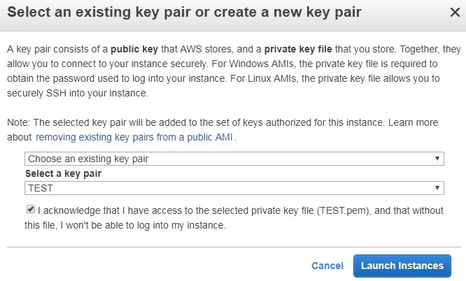
aws instance keypair

On the EC2 Dashboard, access the Instances menu and click on the Instances option.

As you can see a new virtual machine was created.

aws instances

In our example, the virtual machine got the Dynamic IP address: 34.217.14.140

Tutorial – How to Create an EC2 AMI Windows Image

On the EC2 Instance screen, select the Windows virtual machine that will become the Image.

Click on the Action button, access the Image menu and click on the Create Image option.
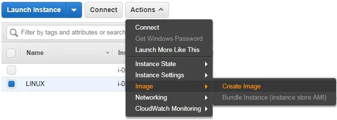
aws ec2 create ami image

On the new image, enter the image name and click on the Create Image button

In our example, an image named MY-IMAGE was created.
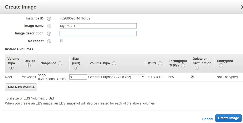
AWS EC2 IMAGE

Wait for the image creation process to end.

The EC2 image creation process might take minutes or hours.

ec2 image confirmation

On the EC2 Dashboard, access the Images menu and click on the AMIs option.

EC2 AMI MENU

Select the AMI Windows Image to create a new virtual machine.

Click on the Action button and select the Launch option.
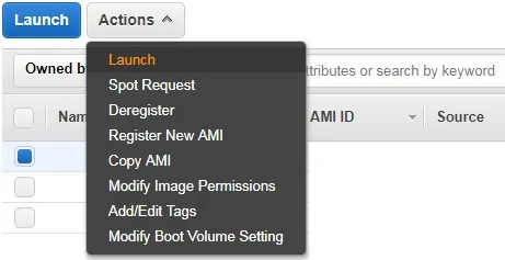
ec2 image launch

Select the type of virtual machine.

Click on the Review and Launch button.

aws ec2 vm type

You have successfully created a Windows Image on Amazon AWS.

Source :
https://techexpert.tips/amazon-aws/ec2-create-ami-windows-image/

Amazon AWS EC2 Snapshot Virtual Machine

Would you like to learn how to create a Virtual Machine Snapshot? In this tutorial, we are going to show you how to create an EC2 Virtual Machine Snapshot using the Amazon AWS cloud.

Amazon AWS Playlist:

On this page, we offer quick access to a list of videos related to Amazon AWS.

Don’t forget to subscribe to our youtube channel named FKIT.

Amazon AWS Related Tutorial:

On this page, we offer quick access to a list of tutorials related to Amazon AWS.

Tutorial – How to Create an AWS EC2 Virtual Machine

On the EC2 Dashboard, access the Instances menu and click on the Instances option.

aws ec2 instances

On the EC2 Instance screen, click on the Launch Instance button.

aws ec2 launch instance

Now, it is time to select the desired Operational system image.

On the list presented, locate and select the Ubuntu Linux image.

In our example, we are going to create a Linux Virtual Machine.

ec2 ubuntu

As the second step, you will have to select the type of virtual machine that will run the Ubuntu Linux.

Basically, you will select the number of processors and the amount of RAM that you want.

aws ec2 vm type

If you do not want to specify the amount of hard disk available to this virtual machine, click on the Review and Launch button.

If you want to specify the amount of hard disk available to this virtual machine, click on the Configure instance detail button.

On the summary screen, click on the Launch button.

aws ec2 launch

Select the Key pair authorized to connect to the new virtual machine and click on the Launch Instances.

In our example, the key pair named TEST was selected.

aws instance keypair

On the EC2 Dashboard, access the Instances menu and click on the Instances option.

As you can see a new virtual machine was created.

aws instances

In our example, the virtual machine got the Dynamic IP address: 34.217.14.140

Tutorial – How to Create an EC2 Snapshot

On the EC2 Instance screen, select the Linux virtual machine that you desire to take a snapshot.

aws ec2 create ami image

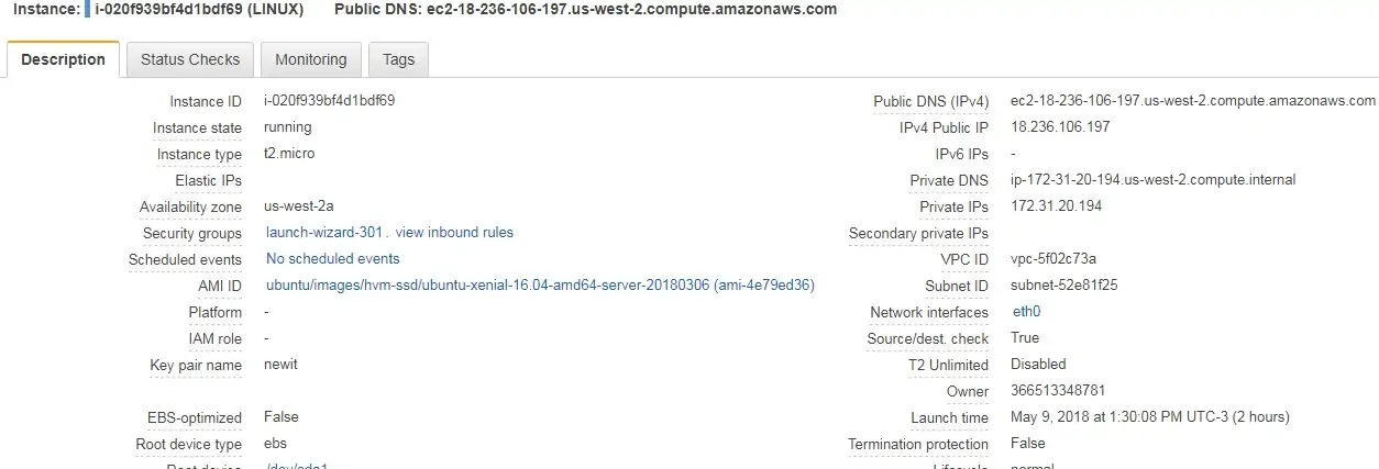
After selecting the virtual machine, the bottom of the screen will show the properties of the virtual machine.

ebs snapshot

On the bottom of the screen, you need to locate and click on the Root drive of the virtual machine

ecs ebs root drive

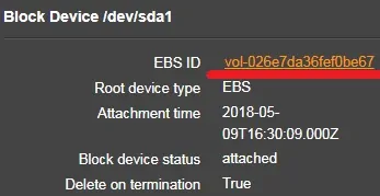
A new window will appear showing the Root drive information.

Click on the ID of the EBS drive to access the EBS menu.

ebs vm snapshot

You will be sent to the Volumes option of the Elastic Block Store menu.

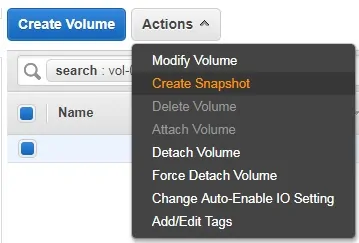
Select the Root drive of your virtual machine.

Click on the Action button and select the Create Snapshot option.

ebs create snapshot

Enter a snapshot identification name.

Wait for the snapshot image creation process to end.

The EC2 image creation process might take minutes or hours.

aws snapshot name

On the EC2 Dashboard, access the Elastic Block Store menu and click on the Snapshots option.

aws snapshot menu

If you want to restore a Virtual machine from a Snapshot.

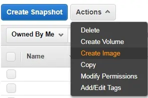
Select the Snapshot that you want to restore.

Click on the Action button and select the Create Image option.

aws create image from snapshot

The process is simple, from a snapshot you will create a new image template.

From the new image template, you will start a new virtual machine.

Don’t forget to turn off the original virtual machine.

ec2 image launch

Select the type of virtual machine.

Click on the Review and Launch button.

aws ec2 vm type

You have successfully created a Linux Image on Amazon AWS.

Source :
https://techexpert.tips/amazon-aws/ec2-snapshot-virtual-machine/

Amazon AWS CLI Installation on Windows

Would you like to learn how to install AWS CLI on Windows ? In this tutorial, we are going to show you how to install the Amazon Command Line Interface on a computer running Microsoft Windows.

Hardware List:

The following section presents the list of equipment used to create this AWS tutorial.

Every piece of hardware listed above can be found at Amazon website.

Amazon AWS Playlist:

On this page, we offer quick access to a list of videos related to Amazon AWS.

Don’t forget to subscribe to our youtube channel named FKIT.

Amazon AWS Related Tutorial:

On this page, we offer quick access to a list of tutorials related to Amazon AWS.

AWS CLI – EC2 Access Key Creation

Open your browser, access the Amazon AWS website and enter your login information.

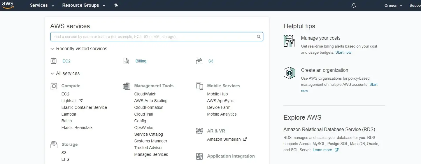
After a successful login, you will be sent to the AWS Dashboard.

aws dashboard

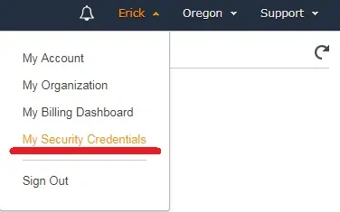
On the top right corner of the screen, click on your username and select the Security Credentials option.

aws security credentials

Select the checkbox and click on the button: Continue to Security Credentials.

aws security key

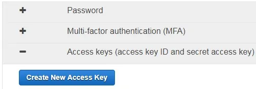
Select the access key tab and click on the Create new access key button.

aws create access key

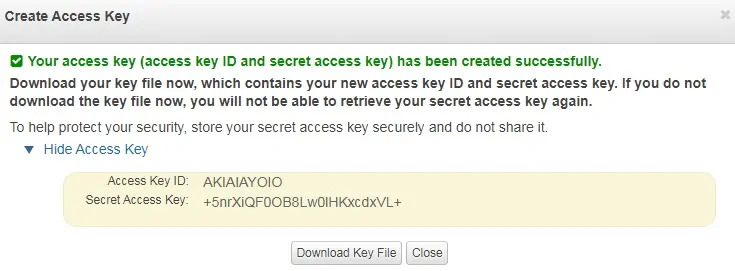
Take note of your public access key and your secret access key.

Keep in mind that there is a limit of 2 AWS keys in use.

aws access key

You have finished the required EC2 key creation.

AWS CLI Installation on Windows

Access the AWS CLI website and download the correct MSI package to you environment.

• Download AWS CLI – Windows 64 Bits

• Download AWS CLI – Windows 32 Bits

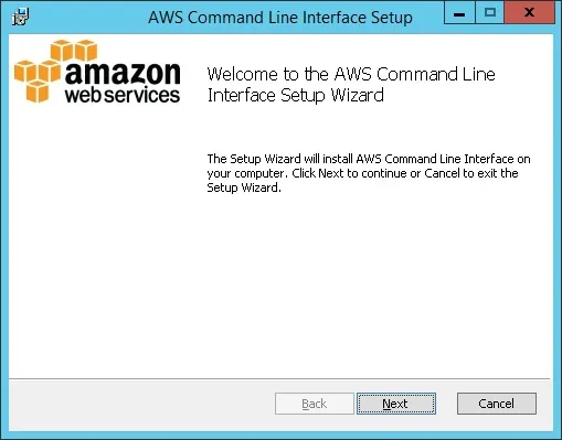
Double click the the AWS CLI package to perform the installation,

aws cli installer windows

After finishing the installation, open an elevated command line window.

On the elevated DOS windows, use the following command to configure AWS CLI.

Use the following command to configure AWS-CLI.

# aws configure

You will be required to enter your key ID and your secret key.

AWS Access Key ID [None]: AKIAIAYOIO
AWS Secret Access Key [None]: +5nrXiQF0OB8Lw0lHKxcdxVL+
Default region name [None]: us-west-2
Default output format [None]:

In our example, we selected us-west-2 as our default region.

If you want to access a list of the available regions click here.

Use the following command to test your communication with the AWS cloud.

# aws ec2 describe-regions

This command will list all regions where the AWS cloud is available.

Copy to Clipboard

{
"Regions": [
{
"Endpoint": "ec2.ap-south-1.amazonaws.com",
"RegionName": "ap-south-1"
},
{
"Endpoint": "ec2.eu-west-3.amazonaws.com",
"RegionName": "eu-west-3"
},
{
"Endpoint": "ec2.eu-west-2.amazonaws.com",
"RegionName": "eu-west-2"
},
{
"Endpoint": "ec2.eu-west-1.amazonaws.com",
"RegionName": "eu-west-1"
},
{
"Endpoint": "ec2.ap-northeast-2.amazonaws.com",
"RegionName": "ap-northeast-2"
},
{
"Endpoint": "ec2.ap-northeast-1.amazonaws.com",
"RegionName": "ap-northeast-1"
},
{
"Endpoint": "ec2.sa-east-1.amazonaws.com",
"RegionName": "sa-east-1"
},
{
"Endpoint": "ec2.ca-central-1.amazonaws.com",
"RegionName": "ca-central-1"
},
{
"Endpoint": "ec2.ap-southeast-1.amazonaws.com",
"RegionName": "ap-southeast-1"
},
{
"Endpoint": "ec2.ap-southeast-2.amazonaws.com",
"RegionName": "ap-southeast-2"
},
{
"Endpoint": "ec2.eu-central-1.amazonaws.com",
"RegionName": "eu-central-1"
},
{
"Endpoint": "ec2.us-east-1.amazonaws.com",
"RegionName": "us-east-1"
},
{
"Endpoint": "ec2.us-east-2.amazonaws.com",
"RegionName": "us-east-2"
},
{
"Endpoint": "ec2.us-west-1.amazonaws.com",
"RegionName": "us-west-1"
},
{
"Endpoint": "ec2.us-west-2.amazonaws.com",
"RegionName": "us-west-2"
}
] }

You have successfully installed the AWS CLI software on a computer running Windows.

Source :
https://techexpert.tips/amazon-aws/aws-cli-installation-on-windows/

GPO – Copy files to remote computers

Would you like to learn how to configure a group policy to copy files to remote computers? In this tutorial, we will show you how to copy files using a GPO.

• Windows 2012 R2
• Windows 2016
• Windows 2019
• Windows 10
• Windows 7

Equipment list

The following section presents the list of equipment used to create this tutorial.

As an Amazon Associate, I earn from qualifying purchases.

Windows Related Tutorial:

On this page, we offer quick access to a list of tutorials related to Windows.

Tutorial GPO – Copy files

Create a shared folder and place a copy of the files.

This will be the distribution point of the files to the network.

GPO - Copy file

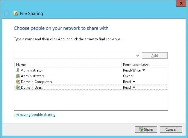
In our example, a shared folder named SOFTWARE was created.

All the domain users and all the domain computers were given read permission over this folder.

GPO - Copy file from share

In our example, this is the path to access the network share.

Copy to Clipboard

\\tech-dc01\SOFTWARE

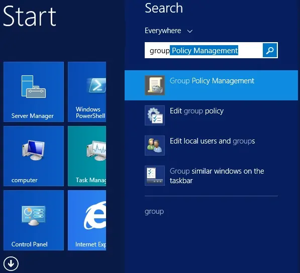
On the domain controller, open the group policy management tool.

Windows 2012 - Group Policy Management

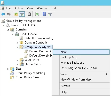
Create a new group policy.

Windows 2012 - Group Policy Objects

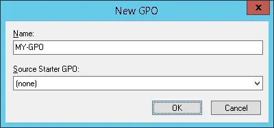
Enter a name for the new group policy.

Windows - Add GPO

In our example, the new GPO was named: MY-GPO.

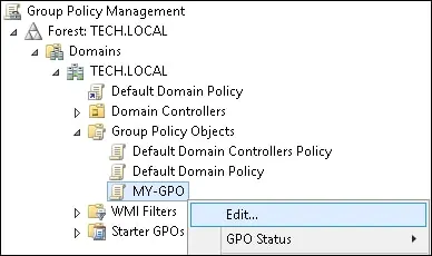
On the Group Policy Management screen, expand the folder named Group Policy Objects.

Right-click your new Group Policy Object and select the Edit option.

Windows - Edit GPO

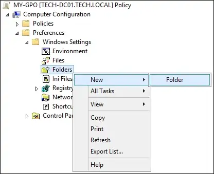
On the group policy editor screen, expand the Computer configuration folder and locate the following item.

Copy to Clipboard

Computer Configuration > Preferences > Windows Settings > Folders

Create a new folder.

GPO - Create a folder

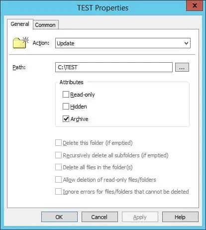
On the General tab, perform the following configuration.

• Action – Update.
• Path – Enter the path to the folder.
• Attributes –  Select the attributes to the new folder.

Click on the OK button.

GPO - Creating new folder

In our example, we are going to create a local folder named TEST on the root of drive C of all computers in the domain.

On the group policy editor screen, expand the Computer configuration folder and locate the following item.

Copy to Clipboard

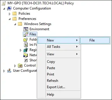
Computer Configuration > Preferences > Windows Settings > Files

Create a new file.

GPO - Copying files

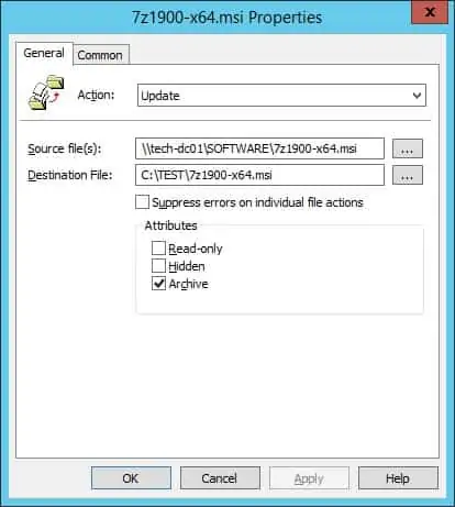
On the General tab, perform the following configuration.

• Action – Update.
• Source – Enter the network path to the file.
• Destination – Enter the local path to save the file.

Click on the OK button.

GPO - Copy file to remote computers

In our example, we are going to copy a file from the network share named SOFTWARE to the local folder named TEST.

To save the group policy configuration, you need to close the Group Policy editor.

Congratulations! You have finished the GPO creation.

Tutorial – Applying the GPO to copy files

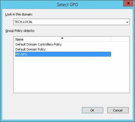
On the Group policy management screen, you need to right-click the Organizational Unit desired and select the option to link an existent GPO.

Windows-2012-Applocker application

In our example, we are going to link the group policy named MY-GPO to the root of the domain.

GPO- tutorial linking

After applying the GPO you need to wait for 10 or 20 minutes.

During this time the GPO will be replicated to other domain controllers.

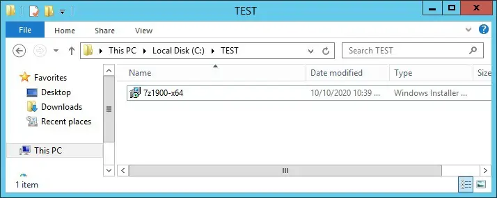
On a remote computer, verify if the GPO copied the file.

Group policy object - Copy files

In our example, we copied a file to all domain computers using a GPO.

Source :
https://techexpert.tips/windows/gpo-copy-files/

Ubiquiti UniFi Network – UniFi Cloud Adoption (Layer 3)

Updated on 5 mag 2023Print

Layer 3 adoption is the process of adopting a UniFi device to a remote UniFi Network Application. This is only recommended for advanced users, or those adopting devices to the UniFi Cloud Console. 

We highly recommend that users refer to Device Adoption for standard device adoption.

L3 Adoption Methods

For layer 3 adoption, your UniFi Network Application and connected devices must have internet access.

UniFi Network Mobile App

The Cloud Console can leverage your UniFi Network Mobile App (iOS / Android) to provide the easiest L3 adoption experience. 

  1. Refer to our UniFi Device LED Status guide to ensure the device is in a factory-default state.
  2. Connect your mobile device to the same local network as your UniFi device. 
  3. Open your UniFi Network Mobile App and connect to site you want to adopt your device.
  4. Your device should appear for adoption.

DHCP Option 43

This option leverages your DHCP server to inform your UniFi device of the location of your remote Network Application host. Those with a UniFi Gateway can easily accomplish this by entering the IP address of the remote Network Application in Option 43 Application Host Address field located in the Network Settings.

For those using a third-party gateway or DHCP server, we recommend consulting your manufacturer’s documentation to learn more.

DNS

You’ll need to configure your DNS server to resolve ‘unifi’ to your remote UniFi Network Application host.

There are two methods of specifying the Network Application host:

SSH

  1. Make sure your device is in a factory-default state. You can refer to our UniFi Device LED Status guide. 
  2. SSH into the device. You may refer to our guide on how to Login with SSH.
  3. Issue the following command: set-inform http://ip-of-host:8080/inform
  4. The UniFi device will now show up for adoption and can be treated as a standard L2 adoption.

Migrating From Another Network Application

A Layer 3 migration is useful for moving devices from a current Network application to a new Cloud Console. See Backups and Migration for more information.

Source :
https://help.ui.com/hc/en-us/articles/204909754

Ubiquiti UniFi Recovery Mode

Updated on 5 mag 2023Print

Recovery Mode is a last-resort solution to recover an unresponsive UniFi device, often resulting from power loss occurring at the same time as an update. Only use Recovery Mode if you are unable to perform a standard factory reset.

Note: UniFi Power Backup can prevent unexpected power losses from occurring.

The following UniFi devices support Recovery Mode:

  • Dream Machine, Dream Machine Pro & Dream Wall
  • Access Points (all models)
  • Cloud KeyCloud Key Gen2+
  • Cameras
  • USW Flex Mini

Before Considering Recovery Mode

If you are considering Recovery Mode, first check two key points:

  1. Reboot your UniFi device. If this resolves your symptoms, no further actions are required.
  2. Factory reset your UniFi device. If you have cloud backups, you can easily restore your settings after factory resetting. If a factory reset works, no further actions are required.

Performing a Device Recovery

Dream Machine, Dream Machine Pro & Dream Wall

  1. Download the most recent firmware for your device, found here.
  2. Completely power-off the UniFi device and unplug it from its power source.
  3. Press and hold the Reset button and then reconnect it to the power source.
  4. Continue holding the Reset button for 5 seconds, or until the display (in supported models) indicates Recovery Mode.
  5. Connect an Ethernet cable from your computer to the first LAN port (Port 1). This is usually the port nearest to the top left corner.
    • Note: Connect to the Dream Wall via Port 18, not Port 1.
  6. Configure a static IP address on your computer in the 192.168.1.0/24 range (for example, 192.168.1.11).

Windows Client

  1. Navigate to the Windows 10 Network connections
    • Settings > Network & Internet > Status > Change Adapter Option
  2. Modify the IPv4 settings of the Ethernet adapter
    • Ethernet Adapter > Properties > Internet Protocol Version 4 (TCP/IPv4) > Propertie
  3. Select the option to manually enter an IP address and add the following information:
    • IP address: 192.168.1.11
    • Subnet mask: 255.255.255.0
    • Default gateway: <blank>
    • DNS servers: <blank>

macOS Client

  1. Navigate to the mac OS Network connections.
    • System Preferences > Networks > Ethernet Adapter
  2. Select to manually enter an IP address and add the following information:
    • IP Address: 192.168.1.11
    • Subnet Mask: 255.255.255.0
    • Router: <blank>
    • DNS server: <blank>
  1. In a web browser, navigate to http://192.168.1.30 to access the Recovery Mode UI.
    • Note: The Recovery Mode UI is accessible via HTTP only (not HTTPS). Your browser may try to redirect your session to HTTPS. Use a different browser if necessary.
  2. Select Firmware Update > Choose and browse your computer for the previously downloaded firmware (.bin) image file.
  3. Wait for the upgrade process to complete and reboot the device afterwards.

Access Points

  1. Download the most recent firmware for your device, found here.
  2. Connect your AP and computer to the same network or VLAN, either through a PoE switch or by connecting the computer directly to the network (data) port on the PoE adapter.
  3. Press and hold the Reset button, and connect your computer to the available ethernet port of the AP.
  4. Continue holding the Reset button until the LED flashes white, blue, off as indicated in our LED Status Guide. This indicates your device is ready for TFTP Recovery and you can release the button.
  5. Set a static IP address on your computer to communicate with the AP, which has a default IP address of 192.168.1.20. The following is an example configuration:
    • Static IP: 192.168.1.25
      Subnet: 255.255.255.0
      Gateway: 192.168.1.20
  6. Use TFTP to move the firmware from your computer to your AP. There are various programs and methods for accomplishing this. Here are two methods for your reference.
    • Windows
      1. Use the built-in TFTP command line tool, or a separate program such as Tftpd64 or pumpKIN.
      2. Select the downloaded firmware image and transfer it to the AP.
    • macOS and Linux
      1. Open Terminal
      2. Enter TFTP mode by entering the command:tftp
      3. Once in TFTP, paste the following commands and hit enter.connect 192.168.1.20
        binary
        rexmt 1
        timeout 60
        put /path/to/firmware_name.bin
  7. The file transfer will begin. The firmware will upgrade and the device will automatically reboot once it has finished. Do not reboot it yourself.

Cloud Key

Cloud Key Gen2, Gen2 Plus

  1. Download the most recent firmware for your device, found here.
  2. Power off the system.
  3. Press and hold the Reset button and then connect it to the power source.
  4. Continue holding the Reset button for 10 seconds, until the LED flashes blue and white. The LCD screen on the front panel will also read “RECOVERY MODE.”
  5. Open your browser and type the IP address for the Cloud Key, visible on the device’s screen.
    • Note: The IP address comes from your DHCP server. If it has not been assigned an IP address, you can try the fallback: 192.168.1.30.
  6. Run the “Check Filesystem” to try searching for and repairing any problems with your storage disk that may cause system issues.
  7. Restore the firmware you downloaded in step (1). Note that this will also factory reset your device.
  8. The LED will flash white while upgrading and turn into a steady white when it is complete.
  9. If your device fails again, this is a sign that you should replace your storage disk.

Cloud Key (Gen1)

  1. Download the most recent firmware for your device, found here.
  2. Power off the system.
  3. Press and hold the Reset button and then connect it to the power source.
  4. Continue holding the Reset button for 10 seconds, until the LED flashes blue and white.
  5. Open your browser and type the IP address for the Cloud Key.
    1. Note: The IP address comes from your DHCP server. If it has not been assigned an IP address, you can try the fallback: 192.168.1.30.
    2. If your Cloud Key does have an IP address assigned by the DHCP server, the fallback IP will not work.
    3. User Tip: If you don’t know your Cloud Key’s IP address, you can use thearp -a SSH command, or software such as nmap to find the IP address.
  6. You will be taken to the Recovery Mode screen. From here you can reset, reboot, power off and most importantly upload an updated firmware bin file.
  7. Upload the firmware you downloaded in step (1).
  8. Once it is uploaded, reboot the Cloud Key to complete the firmware upgrade.
  9. The LED will flash white while upgrading and turn into a steady white when it is complete.

Cameras

  1. Unplug the PoE cable from the camera.
  2. Press and hold the Reset button, then reconnect the camera to its PoE cable.
  3. Continue holding the Reset button for at least 10 seconds, or until you see the LED flash 3 times rapidly.
  4. Release the Reset button.
  5. The device will automatically reboot to an older firmware. 
  6. To update to more recent firmware:
    1. Find your specific camera model at our Downloads page using the left hand menu.
    2. Copy the .bin file link of the firmware.
    3. Use that link to upload it via the webUI of the camera, in System Settings.
      1. Alternatively, adopt the camera to your NVR to perform an upgrade via the NVR-hosted UniFi Video user interface.

USW Flex Mini

  1. Prepare a web server (see below*).
  2. Set the server/computer’s IP to a static 192.168.1.99.
    1. The method to set a static IP on a computer varies from platform to platform. Find instructions in your product’s documentation (Windows, macOS or Ubuntu/Linux).
  3. Download the most recent firmware for your device, found here.
  4. Rename the binary to fwupdate.bin and place it in the directory that was created earlier (webserver).
  5. Power off the switch by unplugging it from its power source.
  6. Press and hold the Reset button and then connect it to the power source.
  7. Continue holding the Reset button for 10 seconds, until the LED flashes blue, white, off.
  8. The USW-Flex-Mini should be updated.

* The first step in the recovery process is to prepare a web server. See below for a walkthrough on your operating system: Windows, macOS and Ubuntu/Debian. 

Prepare a Web Server on Windows

  1. Download Python for Windows (Executable Installer) here.
  2. Open the downloaded file and make sure you select Add Python x.x to PATH during installation.
  3. After the Python installation open Command Prompt as Administrator and confirm that Python is installed correctly with the command below:
    python -V
  4. Create a directory for the web server by running the commands below:
    mkdir c:\webserver
    cd c:\webserver
  5. 5. Start the Python web server on port 80. Note that the version of Python can be found with the command from step 3:
    1. Python 3.x:
      python -m http.server 80
    2. Python 2.x:
      python -m SimpleHTTPServer 80

Prepare a Web Server on macOS

  1. Download Python for macOS here.
  2. After the Python installation open Terminal and confirm that Python is installed correctly with the command below:
    python -V
  3. Create a directory for the web server by running the commands below:
    cd ~
    mkdir webserver
    cd webserver
  4. Start the Python web server on port 80. Note that the version of Python can be found with the command from step 2:
    1. Python 3.x:
      python -m http.server 80
    2. Python 2.x:
      python -m SimpleHTTPServer 80

Prepare a Web Server on Ubuntu/Debian

  1. Install Python on your machine with the commands below:
    sudo apt-get update && sudo apt-get install python3
  2. After the Python installation open a terminal and confirm that Python is installed correctly with the command below:
    python_version=$(dpkg -l | grep “^ii” | awk ‘/python/{print$2}’ | grep “^python[0-9].[0-9]$” | head -n1)
    sudo “${python_version}” -V
  3. Create a directory for the web server by running the commands below:
    cd ~
    mkdir webserver
    cd webserver
  4. Start the Python web server on port 80. Note that the version of Python can be found with the command from step 2:
    1. Python 3.x:
      sudo “${python_version}” -m http.server 80
    2. Python 2.x:
      sudo “${python_version}” -m SimpleHTTPServer 80

Source :
https://help.ui.com/hc/en-us/articles/360043360253-UniFi-Recovery-Mode

Ubiquiti Self-Hosted UniFi Network Server as a Windows Service (Advanced)

Updated on 5 mag 2023Print

Running the UniFi Network application on Windows operating systems can be done using two methods:

  • Launcher – UniFi Network application runs in the foreground (default).
  • Windows Service – UniFi Network application runs in the background (advanced).

NOTES & REQUIREMENTS:

  • Applicable to the latest UniFi Network application versions for Windows.
  • This article applies to UniFi applications that are installed on Windows Desktop (Windows 10 / 11) and not Windows Server versions.
  • Make sure to allow the ports used by the UniFi application through the Windows Firewall. See the UniFi Network – Required Ports Reference article for more information. 

Setting up a new UniFi Network application as a service

ATTENTION:

  • The latest versions of the UniFi Network application (7.3) requires Java 11.
  • Previous versions (7.2) use Java 8.
  • Install only the x64 Java release and only one version of Java.

1. If a previous UniFi Network application is running on the system, download a backup file and then close the launcher.

2. Download the latest UniFi Network application from the Download page and run the setup.

3. You will be prompted to install Java 11. Select the following options and download the x64 .msi file for Windows:

  • Package Type: JRE
  • Version: 11

CRITICAL:

  • If the JAVA_HOME variable is not set correctly, the service installation will not be successful.
  • If you are experiencing issues with the Java 11 installer or the variable, then remove the other/older Java versions that are present on the system.

3. Run the install, and set the Set JAVA_HOME variable to Will be installed on local hard drive

java.png

CLI: Open an administrative Windows Command Prompt (CMD) window.

5. Change the directory to the location of UniFi installation.

cd "%UserProfile%\Ubiquiti UniFi\"

6. Once in the root of the UniFi folder, run the following command to install the service:

java -jar lib\ace.jar installsvc

7. Wait for the installation to complete, indicated by the Complete Installation log message.

8. Start the service with the command below: 

java -jar lib\ace.jar startsvc

9. Open a browser and navigate to the application’s IP address or https://localhost:8443.

Upgrading an existing UniFi Network application as a service

1. Download a backup file of the UniFi Network application. 

CLI: Open an administrative Windows Command Prompt (CMD) window.

2. Change the directory to the location of UniFi installation.

cd "%UserProfile%\Ubiquiti UniFi\"

3. Once in the root of the UniFi folder, issue the following to uninstall the service:

java -jar lib\ace.jar uninstallsvc

4. Wait for the service uninstall process to complete. 

5. Follow step 2 to 9 from the section above.

Source :
https://help.ui.com/hc/en-us/articles/205144550-Self-Hosted-UniFi-Network-Server-as-a-Windows-Service-Advanced-

Ubiquiti UniFi – Explaining the system.properties File

Updated on 2 mag 2023Print

Note that this article is only applicable to advanced users with the self-hosted UniFi Network Servers installed on a Windows/macOS/Linux machine. We generally recommend using a UniFi OS Host for the best experience. Visit UI.com to learn more.

This article describes what the system.properties file is used for, and how to edit it.

Introduction

The system.properties file defines system-wide parameters for the UniFi Network Server. It is found within <unifi.base> in the data folder. Some advanced use-cases include:

  • Manual override of the Application IP Interface (the address to which Devices send inform packets).
  • Advanced Database adjustments.
  • Port Assignments, for purposes of the UniFi Network application communicating with Managed Devices, redirecting Guest Portal traffic, etc.

WARNING: Before editing the file, remember to create a backup of your system. It is also necessary to stop the application before performing any change in the file to avoid errors after changes are made.

The system.properties file can be edited directly via any text editor. Keep in mind that lines preceded by hash-tags (#) exist as comments and are non-operational. Make edits at the bottom of the file. After changing this file, you’ll need to manually trigger provisioning on each site in order to make these effective.

Note: The file is created when UniFi Network runs successfully. If you cannot find the file within the <unifi_base>, create it by running UniFi Network.

Manually Specify the IP Interface for UniFi Network Application Communication

If a UniFi Host has multiple IP interfaces, the following configuration can manually set the exact IP interface that adopted APs should communicate to the Network application:

system_ip=a.b.c.d           # the IP devices should be talking to for inform

Advanced Database Configuration

Below are advanced database configurations that most users will never need. Note: We do not perform tests on these configurations, they are enabled for the convenience of database experts. One possible usage scenario is where few people run their application on a NAS, which has a smaller footprint than a normal server, hence there’s a need to reduce the required resources.

unifi.db.nojournal=false    # disable mongodb journaling
unifi.db.extraargs         # extra mongod args

The configuration below is used to facilitate UniFi Network application installation. Again, most users will never need to set this. When the is_default is set to true, the application will start with factory default configuration. For normal, everyday users, an uninstallation and then fresh re-installation is recommended over this.

is_default=true

From the UniFi Network application you can configure the auto-backup frequency, amount of backups to store, time of backup, etc. At the time of writing this, you cannot change the storage location via the application. We do have a variable in the system.properties if you wish to change the storage location. Currently, the default points to:

1. For Cloud Key: /data/autobackup (where SD card is mounted as /data by default)
2. For software installs: {data.dir}/backup/autobackup

autobackup.dir=/some/path

HSTS can be enabled, but should only be done by advanced system administrators who are familiar with it. If you run into issues, you likely will need to clear your browser’s cache after disabling this and restarting the service. To enable HSTS support add the following:

unifi.https.hsts=true
unifi.https.hsts.max_age=31536000
unifi.https.hsts.preload=false
unifi.https.hsts.subdomain=false 

NOTE: Currently no characters after the custom line(s) are allowed. This includes spaces, pound/sharp signs/comments, etc.

SMTP Related Settings

By default, SMTPS validates certificates and will reject self-signed or untrusted certificates. If your mail server uses an untrusted certificate, you must disable certificate verification with the following:

smtp.checkserveridentity=false

Starting with UniFi Network version 6.1, STARTTLS is opportunistically enabled by default; e.g. will be used if the server announces support for it, and will require a trusted certificate. If using a self-signed or untrusted certificate, you must disable STARTTLS by setting the following:

smtp.starttls_enabled=false

This only controls whether STARTTLS will be used if the server supports it. To force its use, see: starttls_required.

With UniFi Network version 6.1 and newer, STARTTLS is opportunistically enabled by default, but only required if using port 587. This behavior can be overridden by setting smtp.starttls_required=true to force the use of STARTTLS on ports other than 587, or to make STARTTLS optional on port 587, set it to false.

If smtp.starttls_enabled=false is set, the starttls_required value has no impact.

Source :
https://help.ui.com/hc/en-us/articles/205202580-UniFi-Explaining-the-system-properties-File

Ubiquiti UniFi – Tuning the Network Application for a High Number of UniFi Devices

Updated on 4 mag 2023Print

This article only applies to advanced users running UniFi on their own Windows/macOS/Linux machine, to help diagnose and optimize self-hosted UniFi Network Servers running under a high load. We generally recommend using a UniFi OS Host for the best experience. Visit UI.com to learn more.

Notes & Requirements:

  • Ensure you are running the latest version of UniFi Network, found here.
  • This article describes advanced configuration options and should only be attempted by advanced users.
  • Create a backup prior to following the instructions in this article. See UniFi – Backups and Migration for more information.

Caution must be taken when self-hosting a UniFi Network Server if there are hundreds of UniFi devices connected across multiple sites. This increased system load may lead to performance degradation if certain things are not optimized.

Symptom: High CPU Usage

One of the most important metrics to monitor is the CPU usage of the UniFi Host. High CPU usage is the first indication that there is an issue. Unfortunately there is no easy solve for this, and merely increasing the CPU is not always the answer.

Allocating Additional Memory

Before increasing the RAM allocation on your machine, first try increasing the `XMX` and `XMS` options. By default, the UniFi Network application has these set to 1GB. The following lines set the xmx and xms to values to 2GB (2048MB):

unifi.xmx=2048
unifi.xms=2048

The changes above would increase the memory that the UniFi Network application is allowed to consume from 1 to 2GB. Before moving to a machine with more CPU resources, it is recommended to max out the available memory on that machine with the above settings to see if CPU usage decreases.

If 2GB is not sufficient, administrators may want to raise the limit to 4, 8, 16, or even 32GB depending on the scale. In this case it would simply be increasing the value above in increments of 1024, i.e. 4 GB= 4096.

Note: The jstat -gcutil Java command can be used to check whether the memory allocation is sufficient on your machine. See the Oracle documentation for more information.

Increase Mongo WiredTiger Engine Cache

If you already increased the UniFi Network application memory settings to at least 4GB (xmx), you may need to also change the default Mongo WiredTiger engine cache. By default the UniFi Network Application uses:

db.mongo.wt.cache_size=256

On UniFi Network version 6.5.13 and above you can change this setting or let Mongo pick the default value by using:

db.mongo.wt.cache_size_default=true

For more information please refer to Mongo documentation.

Enabling High Performance Java Garbage Collector

If increasing memory does not solve the problem, administrators may consider also adding this line to the system.properties file:

unifi.G1GC.enabled=true

This enables a new Java Garbage Collector that can help optimize performance. However, if after these changes high CPU usage does continue after memory increase, a larger machine with more CPU cores and more memory to handle the workload may be necessary.

Changing Mongo Version/Engine

In persistent cases, administrators may consider updating MongoDB version to 3.2+ with WiredTiger as storage engine, as a means of better scaling their UniFi Network deployment. See the following links for instructions:

Symptom: Heartbeat Missed or Slow to Provision

All devices work by communicating to UniFi Network. These regular inform messages are referred to as “heartbeats”. By default, the application can handle 200 simultaneous device connections so heartbeats shouldn’t be missed unless thousands of devices are being managed. The number of simultaneous inform messages that can be processed can be set in the system.properties file by adding the following lines and adjusting the values to best suit your needs. It does not matter where these lines are added in the file.

inform.num_thread=200
inform.max_keep_alive_requests=100

The default value is 200 and the max_keep_alive_requests value should always be lower than than num_thread. Try adjusting up from there. An increase in device stability should be seen, and by pushing the configuration out to other devices, become even more stable. 

Database Connection Tuning

When running a large UniFi installation, it may be desired to run an external Mongo cluster to be able to scale the database independently from the UniFi Network application. Discussion on that can be found here on our Community Beta forum. If high CPU usage is seen on the Mongo process, it can indicate the need of a bigger box or the need to separate the mongodb process as mentioned above. Once that is done, the following can be tuned to see if it results in better application performance: 

db.mongo.connections_per_host=100
db.mongo.threads_multiplier=5

This results in 500 threads that can be waiting for a Mongo connection. So keep in mind that more threads can mean higher CPU usage because the CPU has to context-switch between threads. It may allow for higher DB throughput, but only if the Mongo process is able to consume more CPU to serve requests faster. 

Source :
https://help.ui.com/hc/en-us/articles/115005159588-UniFi-Tuning-the-Network-Application-for-a-High-Number-of-UniFi-Devices

Ubiquiti UniFi – Repairing Database Issues on the UniFi Network Application

Updated on 1 mag 2023Print

Use this article to repair the database of malfunctioning UniFi Network applications. Please note this only applies to users self-hosting the UniFi Network Server on their own Windows/macOS/Linux machine, or those hosting UniFi Network on a legacy Cloud Key.

We generally recommend using a UniFi OS Host for the best experience. Visit UI.com to learn more. 

Symptoms

  • Statistics are only recorded for a few days and then are cut off or are only intermittently available.
  • Backups including statistics data cannot be generated.
  • Settings-only backups cannot complete, or are created but are unable to be restored due to corruption.
  • An error 400 is generated when trying to open UniFi Network.
  • The UniFi Network application service will not start due to database errors.

32-bit MongoDB Limitations

32-bit MongoDB collections are limited to a total size of 2GB. While running the MMAPv1 storage engine this can cause issues when trying to shrink the aggregate collection sizes. When running a compact command on the MongoDB, the database is rewritten and defragmented without error correction. This process does not return useable disk space to the UniFi Host when the storage engine is MMAPv1.

Getting back that valuable disk space on a 32-bit MongoDB instance will require a repair of the database. This repair may be needed for those who are suspecting invalid entries, corruption, or collection scaling issues. To be able to run a database repair, the Cloud Key will have to have enough free disk space equal to the size of the current data set plus 2 gigabytes. If the dataset has already grown too large to proceed with the db.repairDatabase() command there are instructions below to work around that.

Note: The Legacy Cloud Key (UC CK) utilizes the following:

  • 32-Bit architecture
  • MMAPv1
  • MongoDB Version 2.4.10

Repairing a Cloud Key Database

  1. Establish an SSH connection with the Cloud Key.
  2. Download the mongo pruning script. As written, the script will only keep entries from the past 7 days. It will not remove entries that are required for UniFi administration. Do so by running the following command:
    cd /tmp/ wget https://help.ui.com/hc/en-us/article_attachments/360008640574/CK_repair.js
  3. Stop the UniFi service:
    service unifi stop
  4. The UniFi service will shut down the mongo process. Make sure that the UniFi service has been completely shut down. Repair the database to compact the data entries and free unused disk space field that is included in the query criteria.
    mongod –dbpath /usr/lib/unifi/data/db –smallfiles –logpath /usr/lib/unifi/logs/server.log –repair
    1. NOTE: Steps 5-8 are optional if you need to prune back the database to conserve disk space.
  5. Restart mongo using:
    mongod –dbpath /usr/lib/unifi/data/db –smallfiles –logpath /usr/lib/unifi/logs/server.log –journal –fork
    1. NOTE: Journaling may not be have been enabled in your mongo database. If so, then remove the –journal option in the above command.
  6. Execute the script to prune the stat collections that are causing the problem:
    mongo < /tmp/CK_repair.js
  7. Shut down the mongo server with this command:
    mongod –dbpath /usr/lib/unifi/data/db –smallfiles –logpath /usr/lib/unifi/logs/server.log –shutdown
    1. Note: The last command in the CK_repair.js script is “db.repairDatabase()”. It may result in an error if the stats collections have already grown too large to be repaired while the mongo server is running. If you see such an error running the script then you will need to repair the database from the command line once again by running the command in step 3.
  8. Finally, restart the UniFi service:
    service unifi start

The Cloud Key should now be able to run the Network application. If you still have database issues, please upgrade to the latest Cloud Key Gen2 Plus which does not experience this problem.

Repairing a Debian-based Linux Database

  1. Stop the UniFi service
    service unifi stop
  2. In some cases, where the journal is corrupted, it will be helpful to run the following command before repairing the database, to move it to another location:
    mv -vi /usr/lib/unifi/data/db/journal /usr/lib/unifi/data/db/journal-$(date -I)
  3. Repair the database with this command:
    mongod –dbpath /usr/lib/unifi/data/db –smallfiles –logpath /usr/lib/unifi/logs/server.log –repair
  4. Finally, restart the UniFi service:
    service unifi start
    1. Note: If this process was performed as root the file ownership may have changed. This can be changed with:
      chown -R unifi:unifi /usr/lib/unifi/data/db/
      chown -R unifi:unifi /usr/lib/unifi/logs/server.log

If you still have suspected database issues please migrate to a Cloud Key Gen2 Plus or Dream Machine Pro. These UniFi OS Hosts do not experience this type of database corruption.

Repairing a macOS Database

  1. Create a temporary working directory. For repair purposes, we will call this directory /repair. In terminal:
    mkdir ~/repair
  2. Visit the MongoDB official download website, and download the .tgz release that corresponds to your server’s CPU architecture.
    1. You can also download 2.4.14 here directly: 2.4.14.tgz
  3. Move the downloaded package to your working directory, and extract it by double-clicking it or using the application of your choice.
  4. Locate the bin/mongo binary file, and copy it to your working directory.  At this point, the downloaded .tgz package and any extra extracted files can be deleted as we only need the mongo binary.
  5. Open Terminal and move to your working directory:
    cd ~/repair
  6. Close or stop UniFi.
  7. Repair the database with this command:
    mongod –dbpath ~/Library/Application\ Support/UniFi/data/db –smallfiles –logpath ~/Library/Application\ Support/UniFi/logs/server.log –repair
  8. Open the UniFi application from Finder:
    open -n /Applications/UniFi.app

If you still have suspected database issues please migrate to a Cloud Key Gen2 Plus or Dream Machine Pro. These UniFi OS Hosts do not experience this type of database corruption.

Repairing a Windows Database

  1. Visit the MongoDB official download website, and download the .zip release that corresponds to your CPU architecture.
    1. Note: The recommended MongoDB version is 3.4.x. You can download 3.4.23 directly here: 3.4.23.zip.
  2. Extract \bin\mongod.exe to a working directory of your choice.  In this example, we will use C:\repair\ You may ignore all other files included in the .zip.
  3. Close or stop UniFi.
  4. Open the command prompt by pressing WINDOWS + R.  In the popup, type cmd, and press ENTER.
  5. Enter Working Directory:
    cd C:\repair\
  6. Repair the database with this command:
    mongod.exe –dbpath “%userprofile%\Ubiquiti UniFi\data\db” –smallfiles –logpath “%programfiles%\Ubiquiti UniFi\logs\server.log” –repair
  7. Open the UniFi application.

If you still have suspected database issues please migrate to a Cloud Key Gen2 Plus or Dream Machine Pro. These UniFi OS Hosts do not experience this type of database corruption.

How to Migrate from MMAPv1 to WiredTiger

Attention: This section does not apply to 32-bit architecture hosts including the UC-CK G1.

After UniFi Network is functional again, a user may wish to migrate it to the WiredTiger storage engine.

To verify how much space is used, run the following command:

du -shc /usr/lib/unifi/data/db/ace* /usr/lib/unifi/data/db/journal/* /usr/lib/unifi/data/db/local* | grep total

To verify which MongoDB version is being used, run the following:

mongod --version | grep "db version"

To verify what storage engine version is being used, run the following two commands:

mongo localhost:27117
db.serverStatus().storageEngine.name

How to Migrate to WiredTiger

  1. Create a backup under Settings > Maintenance > Backup with the desired retention settings.
  2. Uninstall UniFi from Windows or macOS. Purge UniFi from Debian-based Linux with the command:
    sudo dpkg -P unifi
  3. Reinstall UniFi on Windows or macOS. Reinstall UniFi on Debian-based Linux with the commands:
    cd /tmp/
    wget <https link to download>
    sudo dpkg -i unifi_sysvinit_all.deb
  4. In the UniFi Setup Wizard restore the backup from step 1.

Source :
https://help.ui.com/hc/en-us/articles/360006634094-UniFi-Repairing-Database-Issues-on-the-UniFi-Network-Application