The previous entries in this section have gone through the most complex sections of Failover Cluster Manager as it applies to Hyper-V. Most of the tool’s remaining functions deal with the supporting infrastructure for a cluster and are much less involved with the virtual machines. If you’re building up and configuring a brand new cluster, these areas are where you’ll spend a lot of your initial time. For a functioning cluster, they still contain useful information but won’t be frequently accessed.
How to Manage Hyper-V Cluster Nodes in Failover Cluster Manager
In the left pane underneath the cluster that you wish to work with, the second tree item is Nodes. This is where you’ll find the physical systems that perform the virtualization hosting for your cluster. If you have hosts that perform other roles for this cluster but are not cluster members, such as storage nodes, they should not appear here.
While it is technically possible for a single cluster to operate multiple roles, such as Hyper-V and Scale-Out File Server (SOFS), a single cluster cannot serve as both the storage platform and the virtualization platform for the same Hyper-V guests. Differing host types should be placed in separate clusters. The only secondary role supported in a Hyper-V cluster is the Hyper-V Replica Broker.
The typical node view should look something like the following. In this cluster, all nodes are present with a status of Up:

There are two context menus to work with in this section. As with all other aspects of Failover Cluster Manager, you can access an object’s context menu by either right-clicking it or by left-clicking it and looking in the panes at the far right.
For the Nodes tree object itself, there is only one unique item: Add Node. Clicking this will take you through the same screens that you saw in the first section of this application’s tour, except that the outcome will be the addition of a new node to an existing cluster rather than the creation of an all-new cluster. If you proceed through the wizard, you’ll be notified of the need to perform a cluster validation. Remember that you might need an up-to-date validation report if you contact Microsoft support.
The other items on the Roles tree node’s context menu are standard. You can customize the columns that appear in the center pane by selecting Customize, which is the only option in the View sub-tree. By default, you are shown the Assigned Vote and Current Vote columns, which give you the status of the cluster’s quorum. There is also an Information column that is usually empty, but will contain a preview of any error states. The last menu option allows you to Refresh the center pane to have Failover Cluster Manager re-check the status of the nodes. Finally, you can click Help to see Failover Cluster Manager’s MMC help window.
The context menu for a node is more complex, although not nearly to the same degree as what you saw for virtual machines in the Roles node.
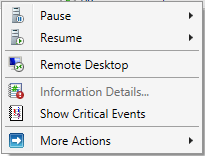
Node Context Menu: Pause
Pausing a node makes it an ineligible target for role migrations. The node is still given a vote for quorum and remains in full communication with the other nodes. This is an ideal state if you wish to perform short-term manual maintenance operations on the node. This menu has two sub-menu items: Drain Roles and Do Not Drain Roles.
If you opt to perform a drain, the cluster will attempt to move all roles on that node to other nodes in the cluster based on its own balancing algorithms. Active guests with a priority of Medium or higher will be Live Migrated; all others will be Quick Migrated. Even if the drain operation is not fully successful, the node will be paused in order to prevent it from accepting any new roles.
Node Context Menu: Resume
The Resume option has the same options as the Pause menu in reverse: Fail Roles Back and Do Not Fail Roles Back. If you choose to perform failback, all roles that were migrated as part of the initial drain operation are retrieved after the node is resumed. Otherwise, they are left where they are.
Node Context Menu: Remote Desktop
This menu option starts the Remote Desktop Client, automatically targeted at the node.
Node Context Menu: Information Details
If any operation resulted in an error status, the Information column will show a short preview. Use this menu item to display the complete error message.
Node Context Menu: Show Critical Events
This menu item will spawn a minimalist event viewer window that shows critical events related to node and quorum management. Despite the implications in the context menu and the spawned window’s title bar text, the events are for all nodes.
Node Context Menu: More Actions
The More Actions menu gives you three sub-items. The first two are Stop Cluster Service and Start Cluster Service. In the current version of Failover Clustering, the outcome of stopping the cluster service in this fashion is very similar to the drain operation, with the exception that the cluster service (clussvc.exe) is gracefully halted. All of the node’s roles are drained and it cannot receive any incoming roles. The node will retain its quorum vote, although Dynamic Quorum may choose to rescind it.
The Start Cluster Service option will not restore drained roles. It will start the service, reattach the node to the cluster, and, if necessary, restore its quorum vote.
The final option on the More Actions menu is Evict. This should only be used when a node is being decommissioned or has failed entirely. In earlier versions of Failover Clustering, evicting a node was a fairly common troubleshooting step. It should no longer be necessary in current versions. Evicting a node does cause configuration information to be lost, so, even if rejoined, pre-existing validation reports may become invalidated.
How to Manipulate Storage for Hyper-V in Failover Cluster Manager
The storage node of Failover Cluster Manager allows you to work with cluster-controlled storage. Hyper-V does work perfectly well with virtual machines that are placed on file servers running SMB (storage message block) protocol version 3 or later. Version 3 debuted with Windows Server 2012. These storage locations are not controlled by the cluster and cannot be managed through Failover Cluster Manager. It can only work with standard cluster disks and Cluster Shared Volumes.
The Storage node has two sub-nodes of its own: Disks and Pools. Pools are used with Scale-Out File Servers
(SOFS). It is technically possible to run Hyper-V roles and SOFS on the same cluster, but the virtual machines cannot be placed on space used by the same cluster’s SOFS. In addition to being unsupported, the system will error if you attempt to create such a “loopback” configuration.
Disks
For a Hyper-V cluster, the Disks sub-node is typically of much greater use. The only situation in which it would not contain any information is if you are not using a disk witness for quorum and all guests are stored on SMB 3 storage. In order for this section to be of any use, you must have connected shared storage to every one of the nodes using common direct-attached storage through an external SCSI interface, an iSCSI link, or a fibre channel link.
Each shared storage location must be formatted with NTFS or ReFS. A disk to be used for quorum must be formatted with NTFS. The details of preparing storage are not part of this tour. Storage will be talked about in more detail in a later article, but you can find detailed guidance on how to connect storage to a Hyper-V system here. Making the connections on the nodes will not automatically make them available to the cluster. That can be done through this section of Failover Cluster Manager.
To begin, select the Disks node in the left pane and access its context menu. The very first item is Add Disk. If there is no unused storage connected to every node, you’ll receive a dialog indicating as much:

If one or more disks are available, you’ll see something like the following:
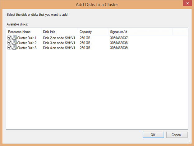
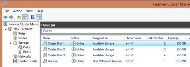
The cluster automatically determines the Resource Name by using the text “Cluster Disk” and incrementing a number. Disk Info helps you to identify what is being connected, as it does not read volume information such as labels. The signature can also be used to identify the disk; it’s retrievable by using Get-Disk. When adding several disks at once that are of equal size, be certain to match them when accessing this screen as it will not be so readily available after being attached to the cluster. Check the box(es) for the disk(s) you’d like to add and click OK. Each disk should then appear in the center pane:
The next item in the Disks sub-node’s context menu is Move Available Storage. Its sub-options are the same for virtual machine migrations: Best Possible Node and Select Node. These items operate only on standard cluster disks; quorum disks and Cluster Shared Volumes are unaffected. Every single cluster disk is moved if possible.
The remaining options in this node are the standard View, Refresh, and Help items which work as they do elsewhere in Failover Cluster Manager.
Disk Items Context Menu
The items in the center pane represent the disk-based storage assigned to the cluster. They have a dynamic context menu. Each item is presented below in alphabetical order.
- Add to Cluster Shared Volumes: This option is only available for standard cluster disks. Once used, the disk is converted to a CSV. It no longer appears as a separate disk attached to a singular cluster node but becomes an entity underneath C:\ClusterStorage on all nodes. A folder named Volume# will be created to represent this disk. It can be renamed, but doing so after virtual machines are placed on it will cause those virtual machines to break. Any virtual machines that were on the cluster disk before it was converted will also be broken.
- Bring Online: This returns an offline object to online status. All disk types are eligible.
- Information Details: If the previous operation on this item in this console resulted in an error, this entry will become active. Clicking it will spawn a dialog with details about the error.
- Move: The Move option is only available for Cluster Shared Volumes. It reassigns ownership to another node, either automatically with the sub-item Best Possible Node or by manual selection using Select Node.
- More Actions: As with the menu it’s found in, this displays a dynamic menu with the following possible options:
- Assign to another role: In a Hyper-V cluster, this menu item is not useful. You do have the ability to assign it directly to a virtual machine role, but that doesn’t grant any special abilities to the virtual machine that it doesn’t already have. Virtual machines can already use any cluster disk as a pass-through disk. Using this menu item could help visually reinforce that a particular virtual machine is using it as pass-through storage.
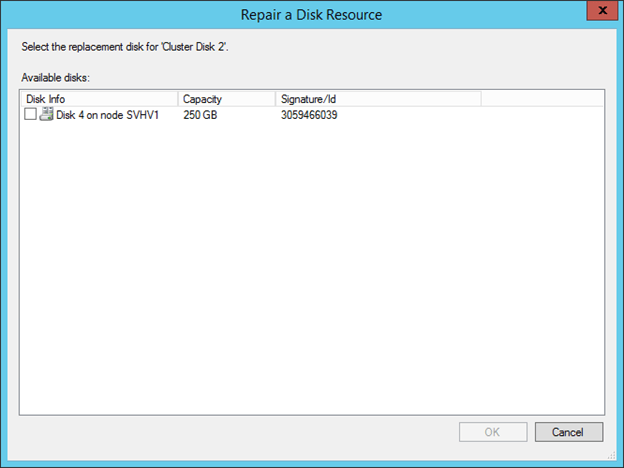
- Repair: This item becomes active for a disk in an offline state. This menu item is to be used In the event that the disk is offline because it has permanently failed and you are replacing it. The replacement disk must be attached to storage but must not have been added as a cluster disk; if it was added, remove it. Upon clicking Repair, a dialog will appear with all available storage. Choose the item that will replace the failed disk.

Upon selecting the replacement item, it will be added into the cluster with the name of the disk that was replaced. You will be prompted to bring it online to complete the repair. - Show Dependency Report: This item is of little use in a Hyper-V cluster as disk resources are not assigned directly to roles. For CSVs, it will display the underlying Cluster Disk resource.
- Simulate Failure: Triggers the configured failure action for a standard cluster disk or the quorum disk.
- Turn off Maintenance Mode: Restores a disk object that was previously placed in Maintenance Mode to normal operation.
- Turn on Maintenance Mode: This mode removes protections against tools such as CHKDSK from running against the volume and disables the cluster’s automated health checks. When activated against a Cluster Shared Volume, you receive a warning that roles will be taken offline; this is not true for virtual machines. However, the volume’s representation under C:\ClusterStorage will disappear and virtual machines in that space cannot be Live Migrated until Maintenance Mode is ended.
- Properties: A properties dialog will be displayed that will change depending upon the selected item. These will be explored after this list.
- Remove: The selected standard cluster disk is removed from cluster disks. Virtual machines on it will instantly crash.
- Remove from role: If a cluster disk is assigned to a role, a menu item will appear allowing you to return it to Available Storage.
- Remove from Cluster Shared Volumes: The selected CSV is returned from CSV status to standard disk status. Any hosted virtual machines will instantly crash.
- Show Critical Events: A minimal event viewer dialog is shown with any available critical events about the selected resource.
- Take Offline: use this to take any disk resource offline. Any active virtual machines using this storage will instantly crash.
Properties Dialog for Cluster Shared Volumes
Of the three cluster disk types, the properties dialog for a CSV is the simplest:
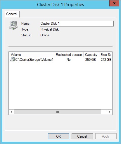
The only modifiable control is the Name. This name is only used by Failover Cluster Manager and Failover Clustering. It does not change the way that virtual machines refer to their storage. You can change this at any time. The list box shows four sets of information. Volume is the logical path that the CSV is referred to on each node. This can be renamed using traditional file system commands and tools, but doing so after virtual machines are created on it will cause their links to break. Redirected Access indicates if the volume is in Redirected Access mode. Capacity shows the total space on the disk and Free Space displays how much of that space is unused.
Properties Dialog for Standard Cluster Disks and Quorum Disks
The properties dialog is identical for the other two types. It contains a series of tabs. The first is the General tab and it looks very similar to the properties dialog for the CSV:
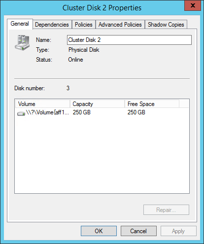
You can use this page to rename the cluster disk. As with a CSV, nothing is harmed by performing this operation. This dialog shows the cluster’s disk number, which can be referenced with the text-based tools and Disk Management. The center pane shows similar information to that of a CSV, although instead of a symbolic link path, the Volume is the drive letter, if one is assigned, or a raw volume identifier. Since cluster disks do not support Redirected Access mode, that column is not present.
The Dependencies tab will not show anything for the typical cluster disk in a Hyper-V environment since they are not commonly attached to roles. The Policies, and Advanced Polices tabs are identical in content and function to those for other cluster resources and were examined in the two preceding articles in this series.
The unique item on this dialog is the Shadow Copies tab. This setting is node independent and should be used instead of the traditional setting in Windows Explorer.
Details Pane
When a single cluster disk is selected in the center pane, that center pane will be divided into upper and lower sections. The lower section will show a quick summary of the item:
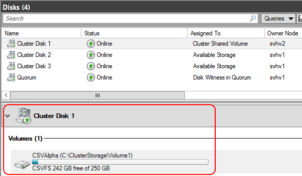
You can quickly see the space utilization for the volume and its drive letter or raw volume identifier (standard cluster disks and quorum disks) or its symbolic link (CSVs). In this pane, the item has a single-item context menu. A quorum or standard cluster disk will have the option to Change Drive Letter, which displays a very simple dialog allowing you to clear the drive letter or assign a new one from the available letters. A Cluster Shared Volume will give you the option to Turn On Redirected Access Mode if it is off or turn it on otherwise.
How to Manage Hyper-V-Related Cluster Networks in Failover Cluster Manager
The next cluster tree item after Disks is Networks. This section gives access to the networking resources as managed by the cluster. Clicking this tree node will display all of the networks that the cluster is aware of in the center pane. By default, the cluster names them as Cluster Network 1, Cluster Network 2, etc.
The way that Failover Clustering identifies a network is by subnet. Every unique subnet discovered on each host will be displayed here. If a host has two or more adapters in the same subnet, only one of them will be displayed. If any host does not have an adapter in a subnet that can be found on other nodes, that network will be considered Partitioned. Configuring the subnets is a topic that’s tackled in the Networking article. As this is just a tour of the tool, it’s assumed that all of your subnets are already configured as desired.
The tree node itself has only a single unique item: Live Migration Settings. The others are the standard View, Refresh, and Help items. Clicking the Live Migration Settings item will display a dialog box similar to the following:
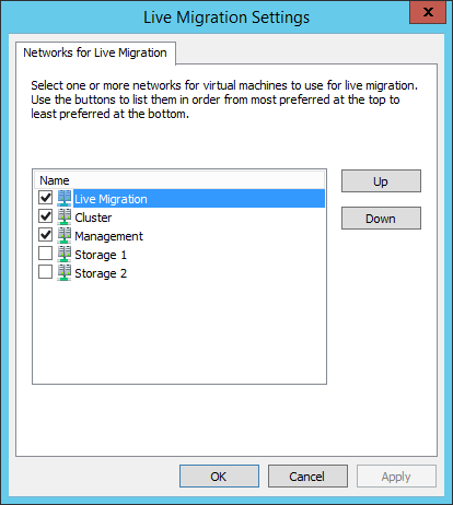
This dialog allows you to prioritize how Live Migration will utilize available networks. It should be used judiciously to prevent Live Migrations from drowning out other types of communication. Live Migration traffic will only be allowed on networks that are checked (those networks must also be marked to allow cluster traffic, which will be demonstrated shortly). Items at the top of the dialog will be given preference when networks are selected. If the sending and receiving nodes are both set to use SMB for Live Migration and SMB multichannel is active, all selected networks will carry Live Migration traffic.
Networks List Entries and Context Menus
The center pane of the Networks section of Failover Cluster Manager looks like the following:
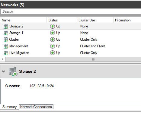
The upper portion shows the name, status, and allowed traffic for each network. The context menu for these items contains only three entries: Information Details, Show Critical Events, and Properties. As is common to previously discussed objects in Failover Cluster Manager, the Information Details link shows a pop-up dialog with details about any error message caused in this session and Show Critical Events displays any error events involving the selected item. Properties opens the properties dialog for the item:
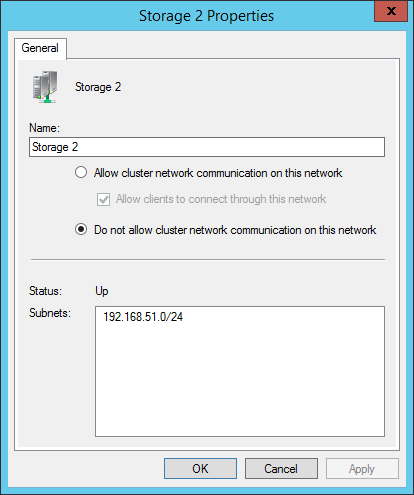
The first changeable control is the name. A network can be safely renamed at any time. The most common use of this feature is to give a meaningful description to the network.
The second control group indicates how the network is to be used.
- Allow cluster network communication on this network grants the ability for cluster communications, such as heartbeat, Redirected Access, and Live Migrations to utilize the selected network.
- Allow clients to connect through this network is not as meaningful in a Hyper-V cluster as for other cluster types. The network that the cluster name object (CNO) appears on should be marked for client access. Clustered Hyper-V does not expose its virtual machine roles through this network the way that other clustered roles do, so this check box serves no other purpose.
- Do not allow cluster network communication on this network prohibits the cluster from using the network at all. This will prevent Live Migration traffic even if the network’s box is checked for Live Migration as shown in the preceding sub-section.
The remainder of this dialog shows the status of the network and the subnets that have been detected on it.
Details Pane
The initial dialog for this section showed the Summary pane for the details section. It displays the name of the network and its detected subnets. There is also a Network Connections tab which shows the adapters in the subnet:

If a network is partitioned, this can help you determine which node(s) have lost connectivity or have failed adapters. It can also help you to verify that adapters have been assigned to the correct subnet. The displayed name (Onboard in the above image) is the same name that the host’s management operating system shows for the adapter. These items have a context menu with the options Information Details and Show Critical Events.
Cluster Events
The final cluster tree node is Cluster Events. This contains a display that is very similar to that of the standard Windows Event Viewer. It has been automatically filtered to contain a specific subset of the cluster-related events. Not all possible events are shown. The default view appears below:
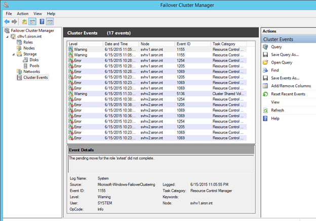
The Cluster Events node does have a context menu, displayed on the right in the above screenshot. It will not be discussed in detail here, as it is quite similar to that found in the traditional Event Viewer. One item to point out to those that are not familiar with that interface is Query. Clicking this will show the following dialog, which you can use to tailor what appears here:
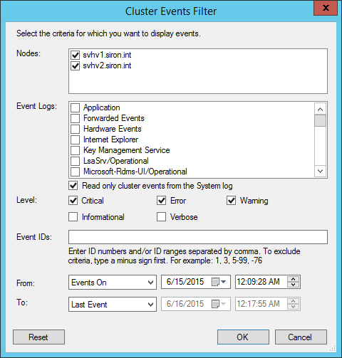
Other items in the context menu can be used to further manipulate the query, if you so desire.
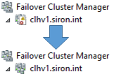
A second notable item in this list is Reset Recent Events. This clears the view, but it does not remove the events themselves. It also has the effect of resetting the icon that Failover Cluster uses for the cluster back to its default as shown below:
Wrapping up in the GUI
This concludes the tour of Failover Cluster Manager and the unit on the built-in graphical tools to manage Hyper-V and Failover Clustering. These sections have taken a very thorough look at these tools and their capabilities and will serve as a reference as you work through the rest of the material and in into the future.
Source :
https://www.altaro.com/hyper-v/failover-cluster-manager/nodes-storage/
