Users locking their accounts is a common problem, it’s one of the top calls to the helpdesk.
What is frustrating is when you unlock a user’s account and it keeps randomly locking. The user could be logged into multiple devices (phone, computer, application, and so on) and when they change their password it will cause ongoing lock-out issues.
This guide will help you to track down the source of those lockouts.
Check it out:
Step 1: Enabling Auditing Logs
The first step to tracking down the source of account lockouts is to enable auditing. If you do not turn on the proper auditing logs then the lockout events will not be logged.
Here are the steps to turn on the audit logs:
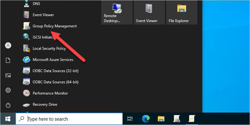
1. Open Group Policy Management Console
This can be from the domain controller or any computer that has the RSAT tools installed.
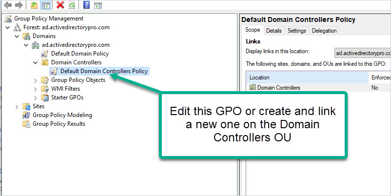
2. Modify Default Domain Controllers Policy
Browse to the Default Domain Controllers Policy, right-click, and select edit. You can also create a new GPO on the “Domain Controllers” OU if you prefer to not edit the default GPO.
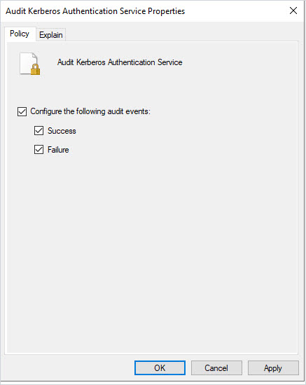
Enable Success and Failure for “Audit Kerberos Authentication Service.”
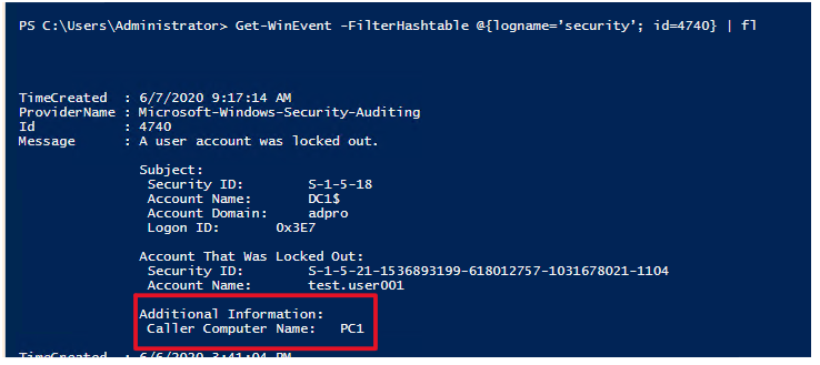
Auditing is now turned on and event 4740 will be logged in the security events logs when an account is locked out. In addition, the Kerberos logs are enabling which will log authentication failures with the lockout. Sometimes event 4740 does not log the source computer and the Kerberos logs provide additional details.
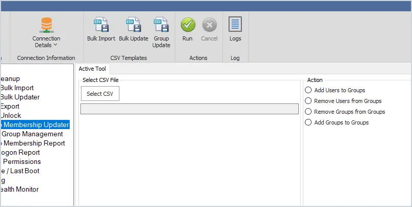
Step 2: Using the User Unlock GUI Tool to Find the Source of Account Lockouts
This step uses the User Unlock Tool to find the event ID 4740 and other event IDs that will help troubleshoot lockouts.
I created this tool to make it super easy for any staff member to unlock accounts, reset passwords and find the source of account lockouts. It also has some additional features to help find the source of lockouts.
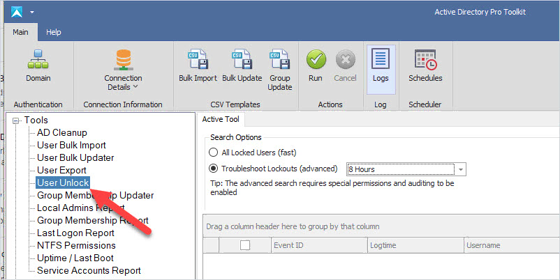
Click on the “User Unlock” tool in the left side menu.
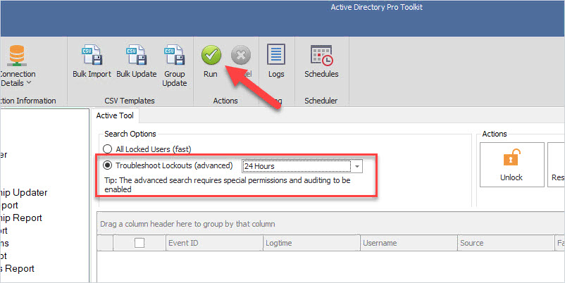
Step 2. Select Troubleshoot Lockouts
Select Troubleshoot lockouts and click run
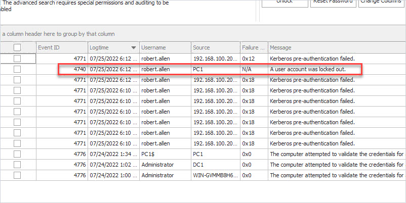
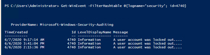
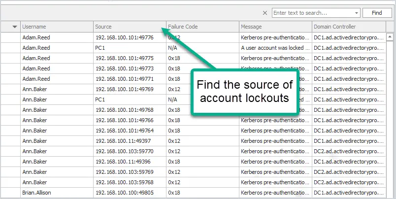
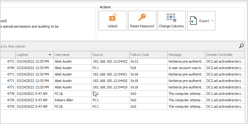
You will now have a list of events that will show the source of a lockout or the source of bad authentication attempts.
In the above screenshot, you can see the account “robert.allen” lockout came from computer PC1.
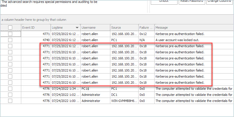
There will be times when event 4740 does not show the source computer. When that happens you can use the other logged events to help troubleshoot log out events. For example, if the above screenshot had no event 4740 I can look at 4771 and see the failed authentication attempt was from a computer with the IP 192.168.100.20.
In addition, you can unlock the account and reset the password all from one tool. The tool will display all locked accounts, you can select a single account or multiple accounts to unlock.
This will display the caller computer name of the lockout. This is the source of the user account lockout.
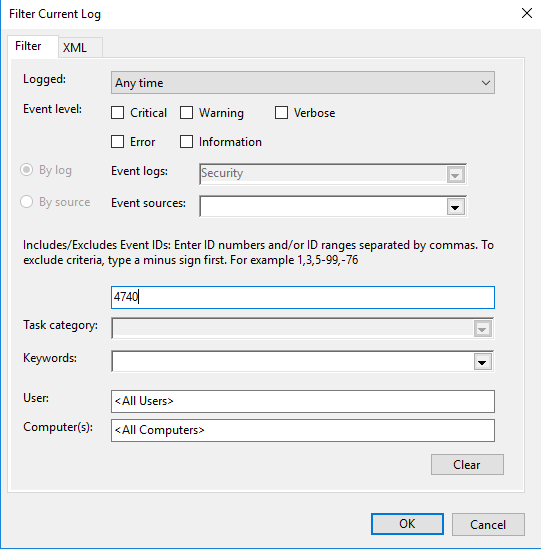
You can also open the event log and filter the events for 4740
Although this method works it takes a few manual steps and can be time consuming. You may also have staff that is not familiar with PowerShell and need to perform other functions like unlock or reset the user’s account.
That is why I created the Active Directory User Unlock GUI tool. This tool makes it super easy for staff to find all locked users and the source of account lockouts.
I hope you found this article useful. If you have questions or comments let me know by posting a comment below.
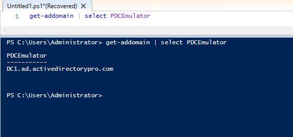
There are times when you need to determine which domain controller you have authenticated to. This can be helpful for a number of reasons such as troubleshooting group policy, slow logins, application issues, map network drives or printers, and so on.
For example, recently I ran into an issue where single sign-on was not working for multiple applications. I was troubleshooting the issue on multiple virtual desktops and noticed that single sign on was working on one of them. I thought this was strange considering all the virtual desktops were the exact same. That is when I checked which domain controller it authenticated against and noticed it was DC2 and all the others were DC1.
How to Check Logon Server
You can check the logon server with either the command line or PowerShell.
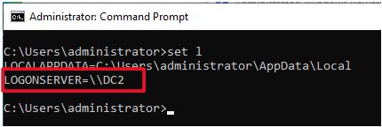
Option 1 – Using the Command Line
Open the command line, type the command below, and press enter
set l
In the screenshot above I authenticated to the DC2 domain controller. The set l command displays everything from the set command that starts with l so it’s displaying the localappdata also. You could just type set logon to see only the logonserver.
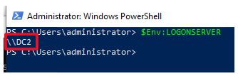
Option 2 – Using PowerShell
Open PowerShell, type the command below, and press enter
$env:LOGONSERVER
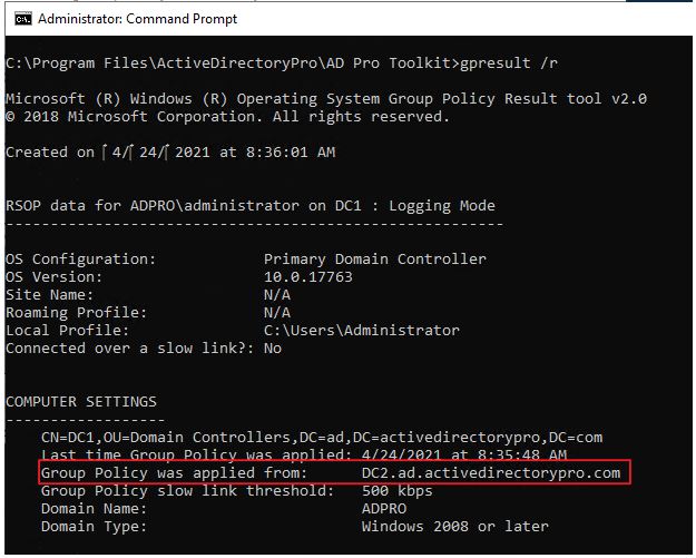
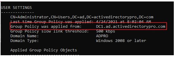
Find Domain Controller Group Policy Was Applied From
If you need to know which domain controller a computer or user applied its group policy settings from then run the gpresult /r command.
gpresult /r
You can see in the above screenshot the group policy was applied from DC2.
Make sure you check the user settings section as the policy could apply from a different domain controller.
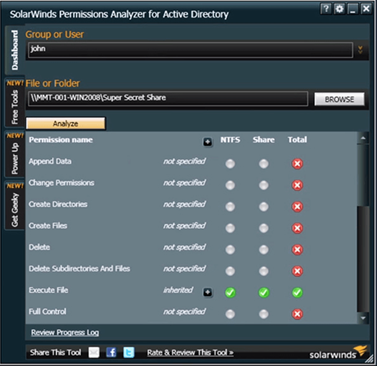
Recommended Tool: Permissions Analyzer for Active Directory
This FREE tool lets you get instant visibility into user and group permissions and allows you to quickly check user or group permissions for files, network, and folder shares.
You can analyze user permissions based on an individual user or group membership.
Is your domain controller dead and do you want to manually remove it?
No problem.
In this guide, I’ll walk through two options to remove a domain controller. If you still have access to the server then option 1 is the preferred choice.
Option 1: Demote a Domain Controller Using Server Manager
Use this option if you still have access to the server.
Option 2: Manually Remove a Domain Controller
Use this option if the server is dead or you no longer have access to it.
In both examples, I’ll be using Windows Server 2016 server but these steps will work for Server 2012 and up.
Tip #1 Starting with Server 2008 domain controller metadata is cleaned up automatically. Windows Server 2003 server or earlier will require using the ntdsutil command to cleanup metadata. With that said you still need to manually remove the server from sites and services.
Tip #2 Make sure there are no other services running on the server (like DNS or DHCP) before shutting down the server. If you can avoid this you may save yourself a big headache.
Tip #3 If the domain controller you are removing has FSMO roles configured they will get transferred to another DC automatically. You can check this with the netdom query FSMO command.
If you don’t like video tutorials or want more details, then continue reading the instructions below.
Option 1: Demote a Domain Controller Using Server Manager
This is Microsoft’s recommended method for removing a domain controller.
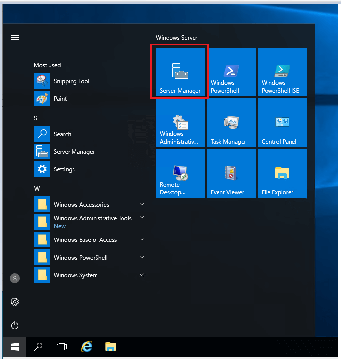
Step 1. Open Server Manager
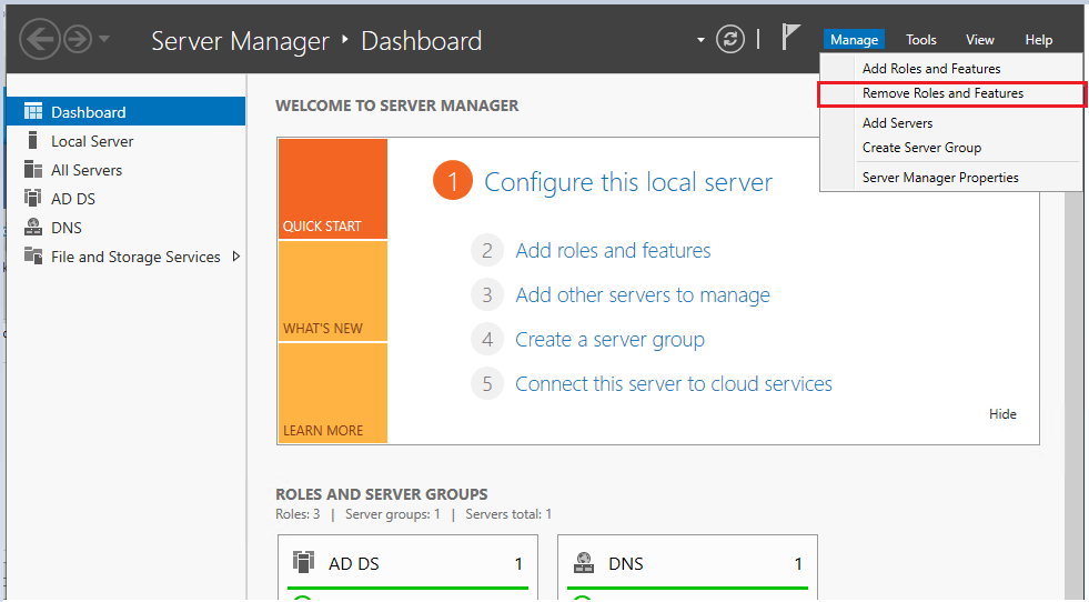
Step 2. Select Manage ->”Remove Roles and Features”
Click next on the “Before you begin page”
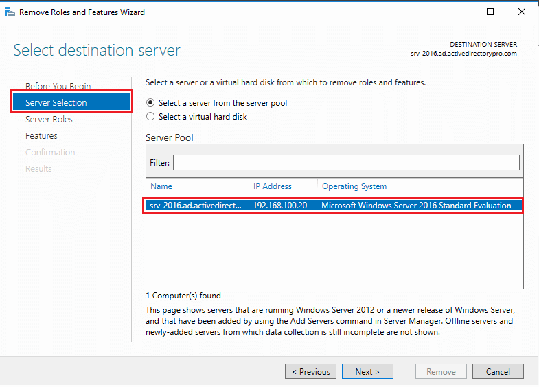
Step 3. On the server selection page, select the server you want to demote and click the next button.
In this example, I’m demoting server “srv-2016”
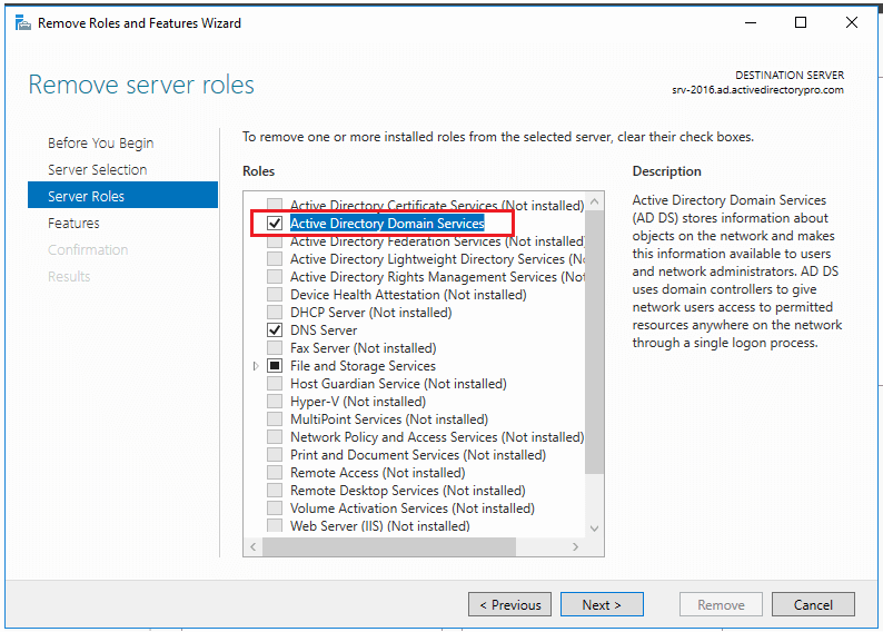
Step 4. Uncheck “Active Directory Domain Services” on the Server Roles page.
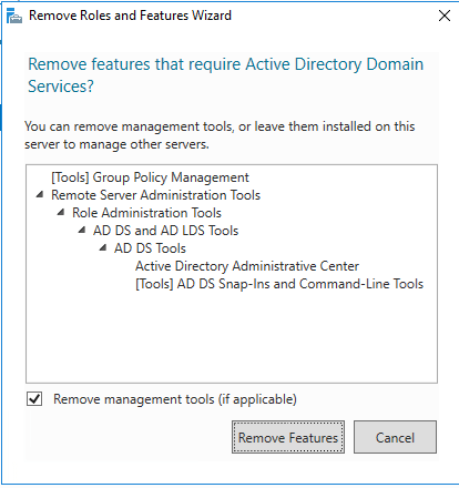
When you uncheck you will get a popup to remove features that require Active Directory Domain Services.
If you will plan on using the server to manage Active Directory then keep these installed. In this example, I plan to decommission the server so I will remove these management tools.
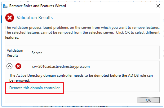
Step 5. Select Demote this domain controller
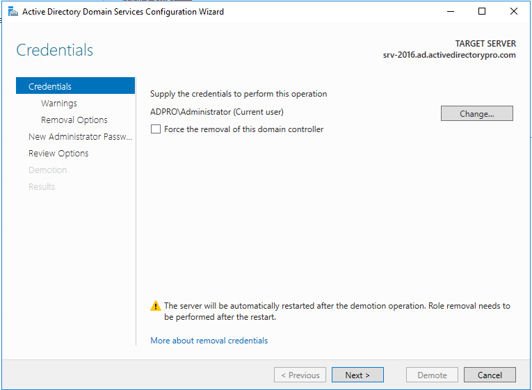
On the next screen make sure you DO NOT select “Force the removal of this domain controller”. You should only select this if you are removing the last domain controller in the domain.
You can also change credentials on this screen if needed.
Click Next
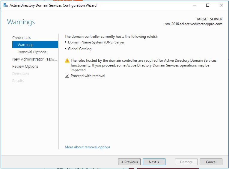
Step 6. On the warnings screen, it will give you a warning this server hosts additional roles. If you have client computers using this server for DNS you will need to update them to point to a different server since the DNS role will be removed.
Check the box “Proceed with removal and click next
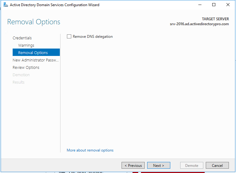
Step 7. If you have DNS delegation you can select “Remove DNS delegation and click next. In most cases, you will not have DNS delegation and can uncheck this box.
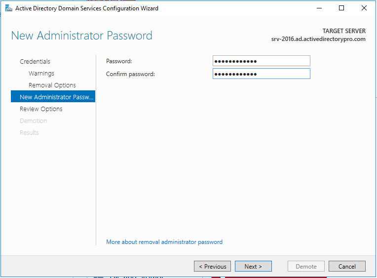
Step 8. Now put in the new administrator password. This will be for the local administrator account on this server.
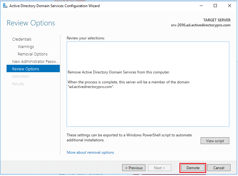
Step 9. Review options and click “Demote”
#Tip – There is a “view script” button that generates a PowerShell script to automate all the steps we just walked through. If you have additional domain controllers to remove you could use this script.
When you click demote the server will be demoted and rebooted. Once it reboots the server will be a member server. You can log in with domain credentials to the server.
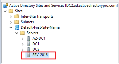
For some reason, Microsoft decided not to include sites and services in the cleanup process. Maybe it’s left there in case you want to promote the server back to a domain controller. If you are not going to promote the server back to a DC then follow these steps.
Open Active Directory Sites and Services and remove the server
You can see above the server I just demoted is still listed in sites and services. I’ll just right-click on it and delete it.
That is it for option 1. You can go into the “Domain Controllers” folder and verify the server is removed. It’s also a good idea to run dcdiag after removing a DC to make sure your environment has no major errors.
You may also need to review and test replication. You can use the repadmin command to test for replication issues.
Option 2: Manually Remove a Domain Controller
Use this option if the server is dead, disconnected, or you just can’t access it. There is really only 1 step.
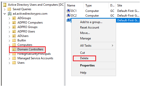
Step 1. On another domain controller or computer with RSAT tools open “Active Directory Users and Computers”
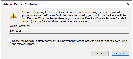
Go to the domain Controllers folder. Right click the domain controller you want to remove and click delete.
On the next screen select the box “Delete this Domain Controller anyway” and click delete”
If the DC is a global catalog server you will get an additional message to confirm the deletion. I’m going to click Yes.
That is pretty much it. Easy hu?
The last step would be to remove the server from Sites and Services just like I showed you in option 1.
As I mentioned at the top of this article starting with server 2008 the metadata cleanup is done automatically with both options. Most how to guides will tell you to open the command prompt and run the ntdsutil to cleanup the metadata. This is not needed if your server operating system is 2008 or above.
It seems easier to just manually remove the DC than going through the server manager wizard. Technically I’m not sure what the difference is but Microsoft recommends using the removal wizard if you can. Use the manual method as a last option.
Summary
In this guide, I showed you two methods for removing a domain controller. Microsoft has made this process very easy by automatically cleaning up the metadata starting with server 2008. As networks and systems are constantly changing there may come a time when you need to remove a domain controller. I’ve provided some Microsoft links below if you would like to read more about this topic.
Did you know inactive user accounts can lead to major security risks?
Center for Internet Security says “it is easier for a threat actor to gain unauthorized access through valid user credentials than through hacking accounts”.
This is just one reason why you should be searching Active Directory for inactive user accounts and disabling them on a regular schedule.
I think you will be surprised at how many inactive and dormant accounts you will find.
In this guide, I’ll show you two methods for finding these risky accounts.
This part is a little long but it explains what user attribute is used to find inactive user accounts. If you are not interested in this then skip to the examples.
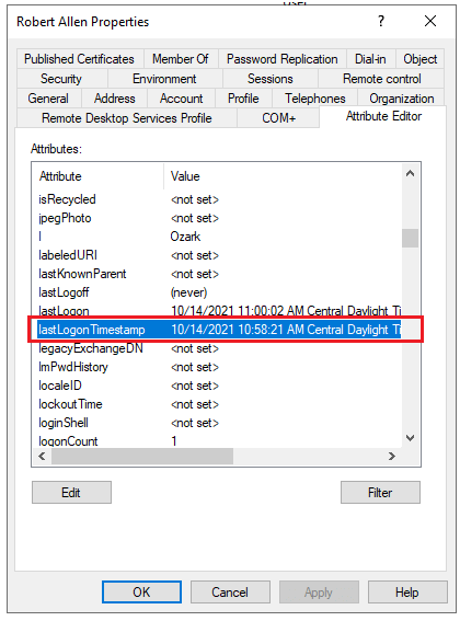
User accounts have an attribute called “lastLogonTimeStamp” the purpose of this attribute is to help identify inactive user and computer accounts. Yes, it can be used for computer accounts also.
There are certain logon types that will update the lastLogonTimeStamp attribute they are, Interactive, Network, and Service logons. Interactive logon is what he cares about, this is when someone logs on at a console.
Let’s look at this attribute in ADUC GUI.
Open an account, click on the Attribute Editor tab and go down to the lastLogonTimestamp attribute.
lastLogonTimestamp in ADUC
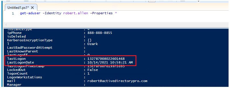
What is the lastLogon value used for?
You can see in the above screenshot there is also a lastLogon value, you will also see this when using PowerShell. The lastLogon value is not replicated to all domain controllers where the lastLogonTimestamp is. This is important because with the lastLogon attribute you would have to query every domain controller to find out when a user logged on. Microsoft understood this and that is why they introduced the lastLogonTimestamp attribute way back in 2003.
You could technically use the lastLogon to find an inactive account but it’s much more difficult.
Now let’s look at this value with PowerShell.
For some reason, Microsoft renamed this value to LastLogonDate in PowerShell.
Why I have no idea but it’s the same value. If you happen to know why Microsoft renamed it in PowerShell please comment below.
Open up PowerShell and run this command.
get-aduser -identity username -properties *
Here is a screenshot of the same account in my domain.
LastLogonDate in PowerShell
You can see that lastLogonTimestamp and LastLogonDate have the same data and time.
Security is the #1 reason for cleaning up inactive user accounts. Here is the complete list.
Security Risks – CIS controls #5 says “There are many ways to covertly obtain access to user accounts, including weak passwords, accounts still valid after a user leaves the enterprise, dormant or lingering test accounts, shared accounts that have not been changed in months or years, service accounts embedded in applications for scripts” I highly recommend you download the CIS controls it is a great source to help defend and secure environments.
Inventory & Tracking Issues – Active Directory is a centralized database. Not only can you use it to track your assets but it can be integrated with other systems for a complete asset management solution. If you don’t cleanup your AD assets then your inventory system will inaccurate.
Ease of management – Kinda along the same lines as#2. A cluttered AD environment leads to a difficult and stressful environment to manage. Think about running a PowerShell script or trying to deploy software to hundreds of computers or users. You will get a lot of returned errors when trying to manage an environment with stale and inactive accounts.
Data Integrity – A lot of these have the same thing, data integrity. Again AD is a centralized database and can be integrated with many systems. If the data in AD is incorrect then all systems connected to AD will be incorrect.
Licensing – Here is a real world exampe. You AD User accounts sync with a 3rd party system such as McAfee. Mcafee charges you based on user accounts. If you have hundreds of inactive accounts syncing with 3rd party products you could be paying for a lot of extra licenses you don’t need. This is the case when syncing AD with cloud products also.
Best Practices for Removing Inactive User Accounts
Here are some best practices for cleaning up inactive users or computer accounts.
Never immediatly remove accounts that are identified as inactive. Disabled them first for at least 30 days (longer the better).
Search for accounts with a lastLogonTimestamp that is 45 days or older, meaning the AD account shows no logon activity for 45 days or longer.
Disable the accounts for at least 30 days, I typically go with 60. With remote access, VPNs, laptops sometimes AD doesn’t get updated. By disabling an account first its very easy to re-enable it and give the user their access back.
Add a description to the account with the date disabled and your initians. This is very helpful for other admins in case someone asks why an account is disabled.
An inactive on premise account might not mean an inactive Office 365 account. This would be for hybrid environments that sync with Office 365. The disabling of the account vs immedialy deleting is critical for these types of environments. You could have users working from home that never authenticate to the on prem AD environment but log into office 365 daily.
Run the cleanup process every month.
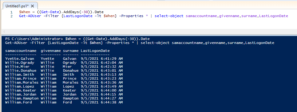
Example 1: Find Inactive User Accounts with PowerShell
To find inactive accounts with PowerShell you will need the RSAT tools installed or run these commands on the domain controller.
All of these examples use the LastLogonDate attribute that I went over in the first part of this article.
In the above example, I added | Disable-ADAccount at the end to disable all inactive accounts.
You can also use these commands to search computer accounts just change Get-ADUser to Get-ADComputer
As you can see It’s easy to identify inactive user accounts with PowerShell by filtering on the user’s LastLogonDate. If you are into PowerShell you can create a very powerful tool for cleaning up AD.
If you are not into PowerShell or just want a simple GUI tool then check out example 2.
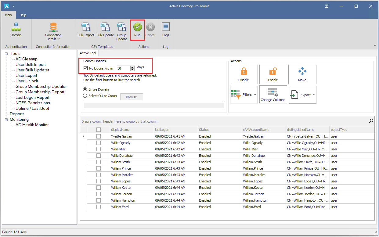
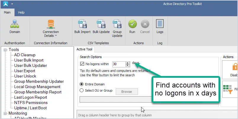
Example 2: Find Inactive User Accounts with the AD Cleanup Tool
The AD Cleanup Tool makes it extremely easy to find inactive users and computers. I also added filters to quickly find expired users, disabled and users with no logon history. These are often forgotten accounts that also should be part of the cleanup process.
Let’s look at an example
To find all inactive accounts for the last 30 days just enter 30 in the search options and click run. You can enter any number into the search options box.
Search inactive accounts in the last 30 days
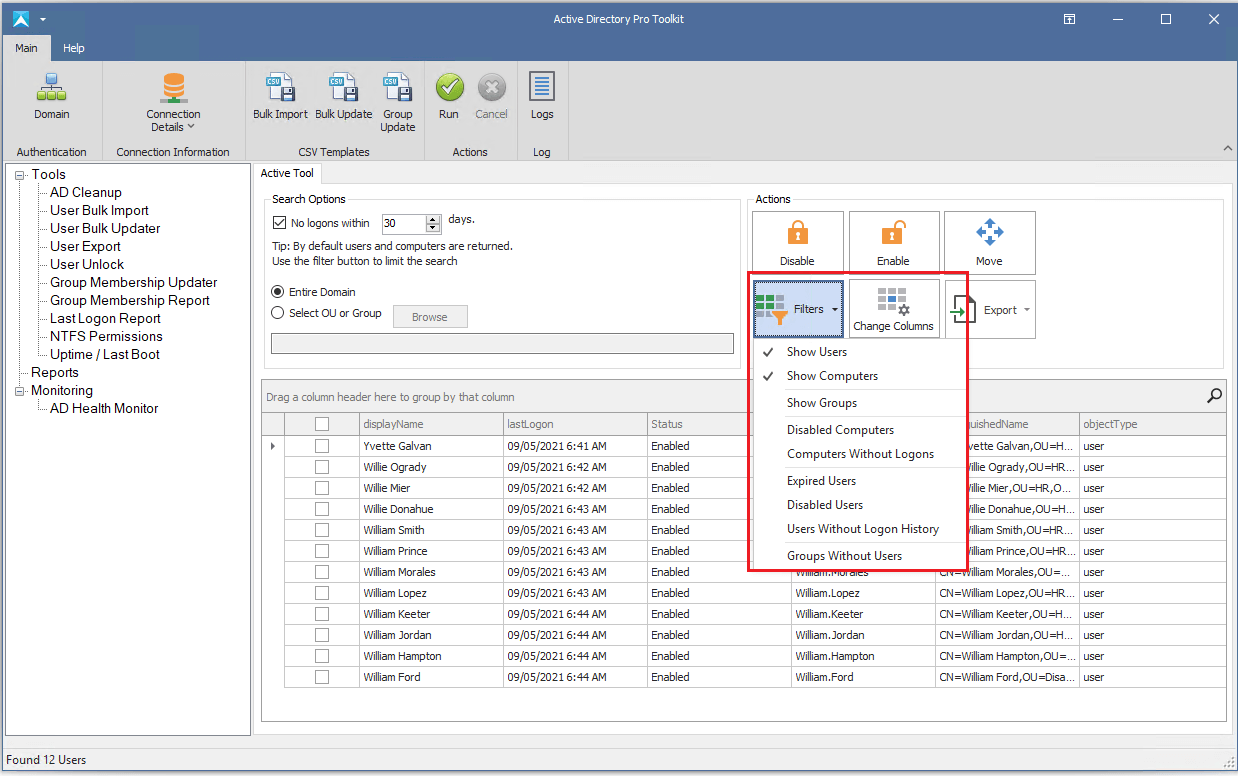
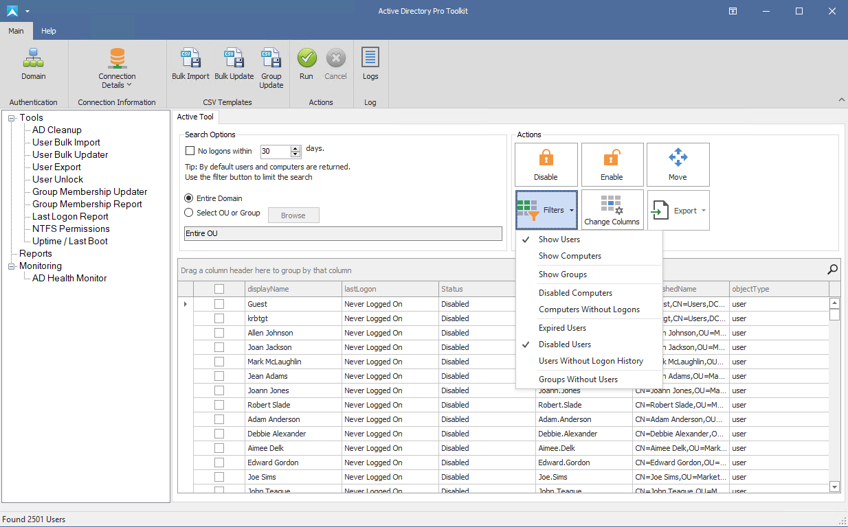
By default, this tool will display both inactive user and computers. To view just user accounts, uncheck “show Computers” from the filters dropdown.
Change the filter to list just user accounts
This searches the entire domain.
You can limit the search by choosing an OU or group. For example, I want to check for inactive accounts in all of my accounting security groups. I click browse and now I can select all my groups or any OUs.
Select OU or groups to search
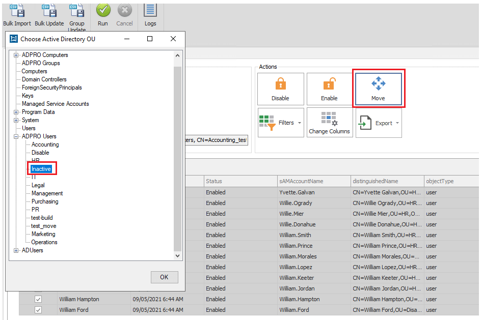
To disable or move the accounts I just select them and then click the action button.
I’m going to move these accounts to an Inactive OU I created. I click the move button then select the OU.
Select OU to move accounts into
Now I’ll check ADUC to verify the accounts have been moved. This makes it easy to see all the accounts that I’m going to disable because they are identified as inactive.
If you wanted to see all disabled user accounts, just drop down the filters list and select disabled users.
Display all disabled user accounts
In the screenshot above you can also quickly display all expired user accounts and users with no logon history by simply selecting them in the filter. You can then take action on these accounts by moving or disabling them.
There are a lot of options with this tool and the easy to use interface saves you valuable time when it comes to cleaning up your AD environment.
Summary
I showed you two examples for finding and removing inactive user accounts in Active Directory. I highly recommend you add this to your monthly maintenance checklist. Security is a big concern with Active Directory but as I pointed out there are several reasons why this is an important task. PowerShell is a great option for finding inactive accounts but does require knowledge of scripting. For those that are not into scripting or just want a quick and simple solution, there is the AD Cleanup GUI Tool.
In this tutorial, I will demonstrate moving Active Directory users from one domain to another.
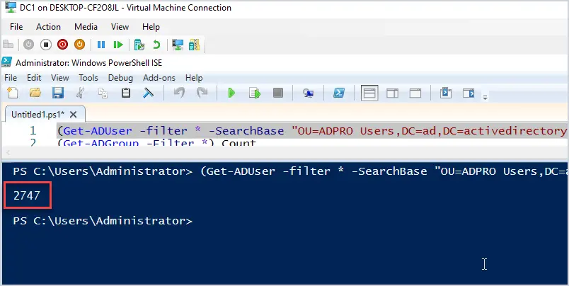
I’m going to move 2747 users from one domain (running server 2019) to a new domain running server 2022. You can move accounts to an existing domain or a new one.
The tools used in this guide will work with domain controllers running 2008 and later operating systems. Also, you can move accounts in the same domain forest, a different forest, domain trust, or no trust.
Reasons for moving users:
Creating a test environment
Merging with another company
Moving or upgrading to a new server
No trust between domains
Moving users to a single domain (consolidating domains)
Steps for Moving Users From One Domain To Another Domain
To complete the move I will use some PowerShell scripts to re-create the OUs and groups. I’ll then use the export and import tool from the AD Pro Toolkit to move the accounts.
Note
This method does not migrate computer user profiles or SID history. It will move user data from Active Directory such as OUs, group membership, and user fields (address, manager, phone number, state, etc).
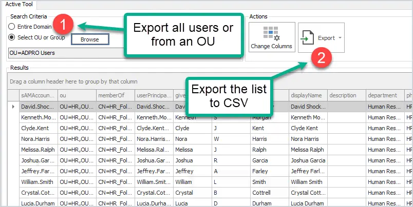
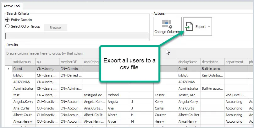
With the export tool, you can select to export from the entire domain, an OU or group.
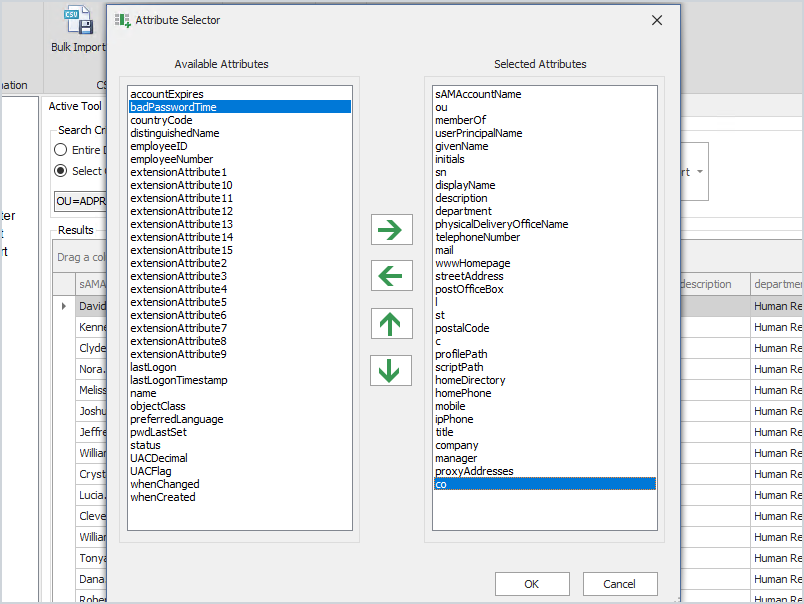
You can also change the columns to preserve user settings when moving to the new domain.
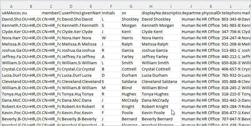
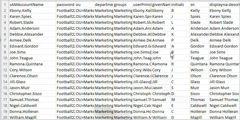
Below is a screenshot of the CSV file exported from my source domain. I exported 2747 users and it includes 31 columns of user properties. Again, you can use the attribute selector to add or remove columns. These user properties will be preserved and imported into the other domain.
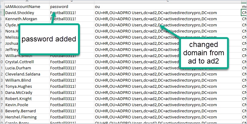
2. Modify CSV File for the new domain
To import these accounts into the new domain you will need to add a password column. If it is a different domain you will also need to modify the OU path. I’m going from ad.activedirectorypro.com to ad2.activedirectorypro.com so I’ll need to update the ou path. You can easily do this in excel with a search and replace.
You can change additional details in the CSV to reflect the new domain. For example, you can change proxyAddresses to the new domain name or change the userPrincipalName.
Now I’m ready to import all 2747 accounts into the new domain. This will import them into the new domain, add them into the OUs, add to groups and keep their user settings from the old domain.
3. Import Users Into the New Domain (or existing domain)
If you are moving the users to an existing domain you probably don’t need to create OUs or groups. If it’s a new domain and you want to replicate the AD structure of the source domain then you can use some PowerShell scripts. See the links below for step by step instructions.
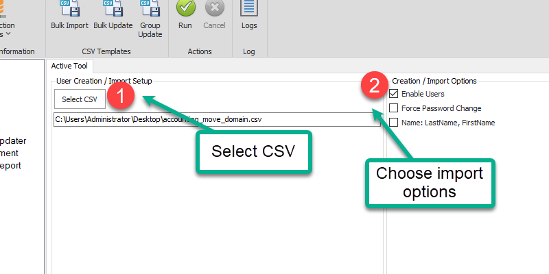
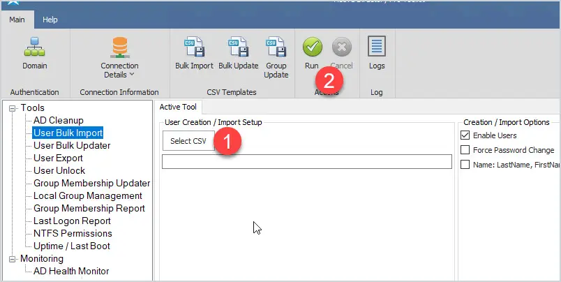
Select the CSV file, your import options, and click run.
When the import is complete you can check the logs and Active Directory to verify the import.
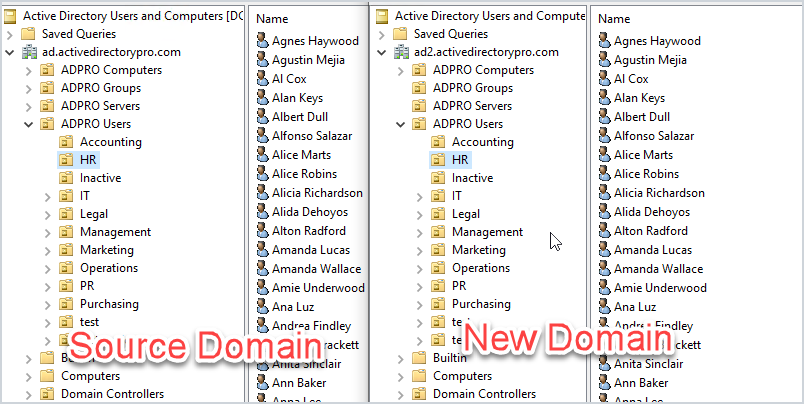
Above you can see a screenshot of the source and the new domain. All of the accounts are imported into the same OUs and groups.
Using the export and import tool makes it really easy to move users to a new domain while keeping their group membership and user properties from Active Directory. It also is very flexible as you can move users from an old domain such as 2008 to a newer server like 2019 or later.
You also don’t have to worry about trust relationships or connections between the two domains.
Below are some PowerShell commands to help you verify the numbers in Active Directory.
Count the Number of Active Directory Objects using PowerShell
Here are some PowerShell commands I used to count the number of objects in the source domain.
Get the number of AD users
(Get-ADUser -filter *).count
The above command gets the count for all users in the domain. To get the count for just an OU use this command. Change the SearchBase to the path of your root OU.
2747 is the number of users in my source domain so this means all the users imported into the new domain successfully.
Get the number of AD Computers
(Get-ADComputer -Filter *).count
Get the number of Organizational Units
(Get-ADOrganizationalUnit -filter *).count
Get the number of AD Security groups
(Get-ADGroup -Filter *).Count
Conclusion
That’s how you move users from one domain to another using tools from the AD Pro Toolkit and PowerShell. An alternative to moving users to another domain is by using the Microsoft Active Directory Migration Tool. The ADMT (Active Directory Migration Tool) will migrate SID and computer profiles. The only problem with this tool is it is not updated, has no support, and often fails. It also is not as flexible as the method I demonstrated in this guide.
Do you need to transfer FSMO roles to another domain controller?
No problem, it is very is to do.
In this tutorial, I’ll show you step-by-step instructions to transfer the FSMO roles from one domain controller to another. I’ll show you two methods: the first is using PowerShell and the second is using the ADUC GUI.
Why Transfer FSMO roles?
By default, when Active Directory is installed all five FSMO roles are assigned to the first domain controller in the forest root domain. Transferring FSMO roles is often needed for several reasons including:
Taking a domain controller offline for maintenance
Performance issues
It is recommended to only transfer FSMO roles when the current role holder is operational and is accessible on the network. For a complete list of considerations see the MS article Transfer or seize FSMO Roles in Active Directory Services.
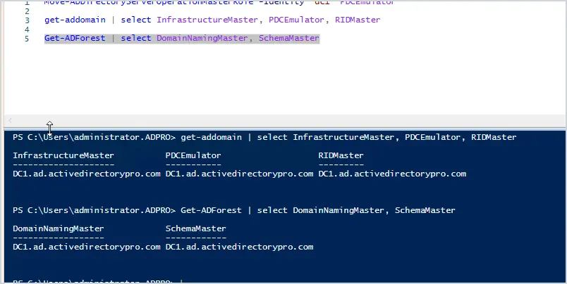
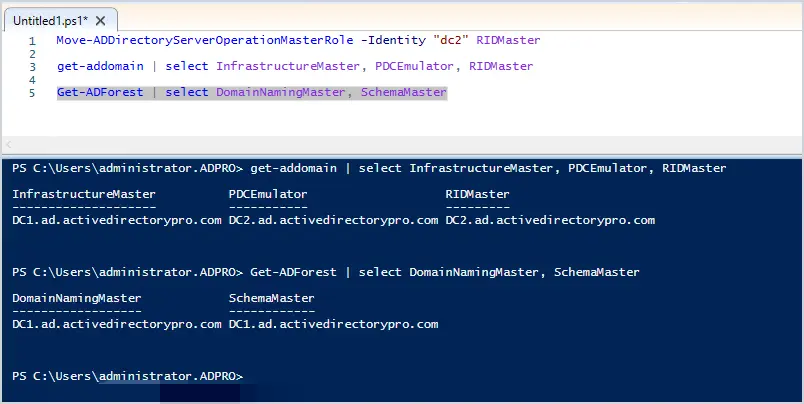
Step 1: List Current FSMO Role Holders
Before moving the FSMO roles it is a good idea to check which domain controllers hold which roles.
You can list which domain controllers hold FSMO roles with these two PowerShell commands:
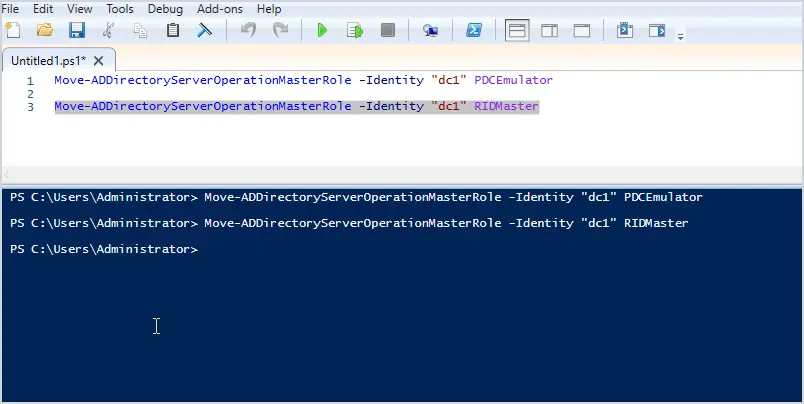
Here is a screenshot of when I moved PDCEmulator and RIDMaster to DC1.
Now if I re-run the commands to list the FSMO roles I should see them all on DC1.
Yes, I have confirmed all the roles are now on DC1. As you can see moving FSMO roles with PowerShell is very easy to do.
Now let’s see how to transfer FSMO roles using the Active Directory Users and Computers GUI.
Transfer FSMO Roles Using ADUC GUI
Just like PowerShell you need to log into the server that you will be transferring to. I’m transferring from DC2 to DC1 so I’ll log into DC1.
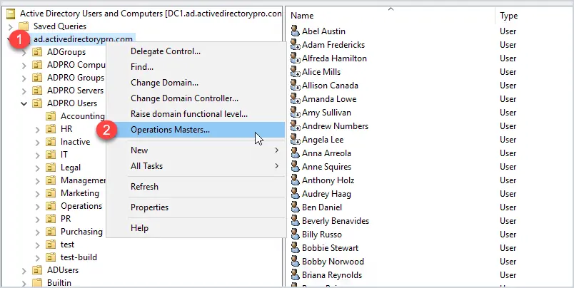
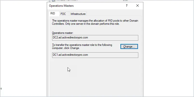
Open the Active Directory Users and Computers console, then right-click on the domain and click on operations masters.
You should now see a screen with three tabs (RID, PDC, and Infrastructure).
To transfer one of these roles just click on the change button. You can’t select which domain controller to transfer the role to, that is why you need to log into the server that you want to transfer to. if I wanted to transfer the RID role to DC3 I would log into that server.
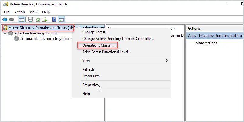
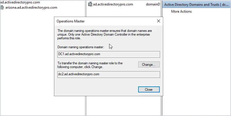
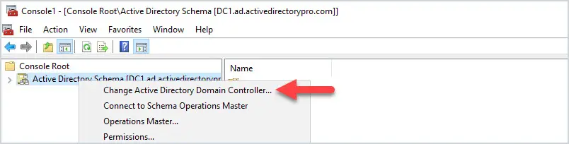
To transfer the domain naming operations master role you will need to open Active Directory Domains and Trusts. Right-click on “Active Directory Domains and Trusts” and select “Operations Master”.
Now click change to transfer the role to another DC.
To transfer the schema master role follow these steps.
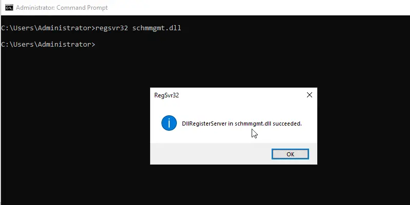
Open a command line and run the command regsvr32 schmmgmt.dll
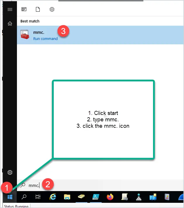
Next, you need to open an MMC console. To do this click on start then type mmc. and click the icon.
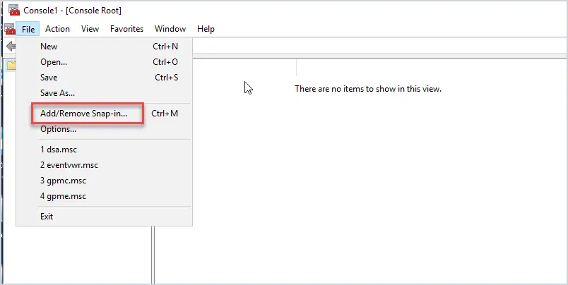
Next, click File, then Add/Remove Snap-in
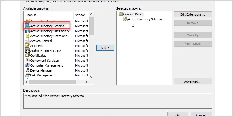
Add “Active Directory Schema” from the list and click ok.
Right click on “Active Directory Schema” and change the domain controller to the server you want to transfer the role to.
In this example, I’ll change the domain controller to DC2.
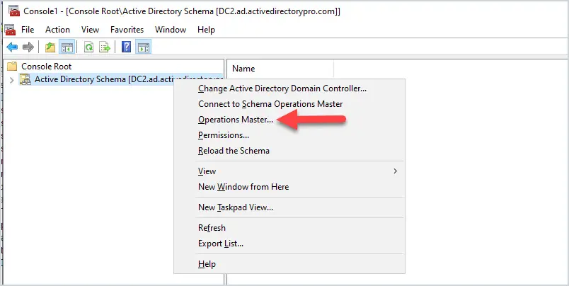
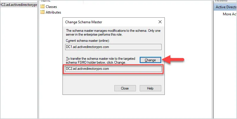
Now you can right-click on Active Directory schema and select “Operations Master” to transfer the schema master role.
Confirm the role is changing to the correct DC and click the “change” button.
As you can see transferring FSMO roles with the GUI takes a lot of extra steps and that is why I prefer to use PowerShell. But if you are not into Powershell then the GUI works just fine.
Summary
Moving FSMO roles to another server is not a daily task but is necessary at times. Microsoft recommends the server be online when moving roles. The steps in this tutorial should help you when it comes time to move roles.
A list of the best Active Directory tools to help you simplify and automate Microsoft Active Directory management tasks.
The native Windows Administrative Tools are missing many features that administrators need to effectively do their jobs. Things like bulk operations and automation are just not possible with the Active Directory users and computer consoles.
The good news is there are many useful Active Directory Tools to choose from that can help you manage domain users, groups, and computers, generate reports, find security weaknesses, and more.
The Bulk Import tool makes it easy to import new user accounts into Active Directory from CSV. Includes a CSV template, sets multiple user attributes, and adds users to groups during the import. Automate the creation of new user accounts and simplify the user account provisioning process.
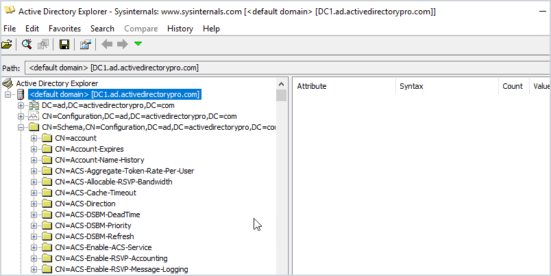
Active Directory Explorer is a browser to navigate the AD database, objects, permissions, and schema objects within Active Directory. The interface is similar to Active Directory users and computers but allows you to view advanced settings. This is not a tool you would use on a daily basis, this would be used for very specific tasks such as viewing an object’s attributes and security sessions.
Another neat feature is the ability to save a snapshot of the AD database. You can then load it for offline viewing and explore it like it was a live database. Again not a common use case.
Adaxes is a premium product that automates many AD management tasks, like user provisioning, assigning permissions, creating mailboxes, delegation, and much more. All management tasks are done from a web interface and can be accessed from laptops, tablets, and phones. The web interface is fully customizable so you can view just want you to need. Also includes a user self service portal and a password self service portal.
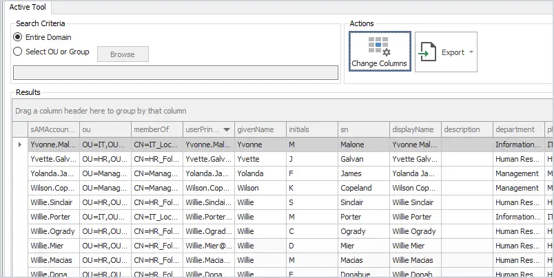
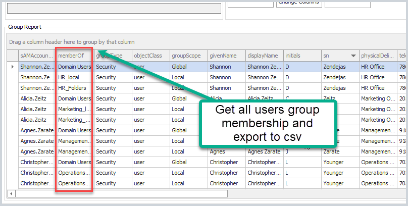
The user export tool lets you export all uses plus all common user fields to a CSV. Over 40 user fields can be added to the export by clicking the change columns button. This is a great tool if you need a report of all users, the groups they are a member of, OU, and more.
Key Features
Find users TRUE last logon date from all domain controllers
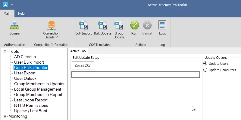
This tool lets you bulk update user account properties from CSV file. Some popular use cases are bulk updating user’s proxyaddresses, employeeid, addresses, manager, addresses, state, country, and so on.
All changes are sent to a log file which lets you keep track of changes and check for errors. This is a very popular tool!
The AD Cleanup tool searches your domain for stale and inactive user accounts based on the account’s lastlogon attribute. You can also find disabled, expired, accounts that have never been used and empty groups.
It is recommended to run a cleanup process on your domain at least once a month, this tool can help simplify that cleanup process and secure your domain.
This utility was designed to Monitor Active Directory and other critical services like Azure, DNS, and DHCP. It will quickly spot domain controller issues, replication, performance issues with cloud services, failed logon attempts, and much more.
This is a premium tool that has a big price tag but it’s an incredible product. You can monitor all resources including applications, hardware, processes, and cloud systems. Everything is accessed from a single web console, you can get email alerts based on various thresholds.
If you want a simple tool to monitor your Active Directory services then this is a great tool.
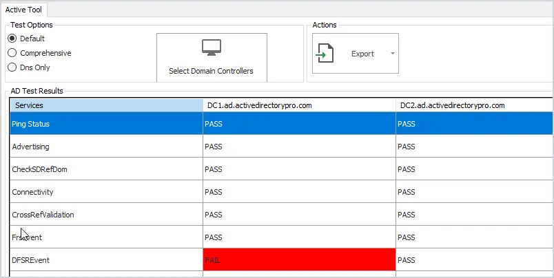
Check the health of your domain controllers with this easy to use tool. Runs 27 health checks on your servers to check for critical errors. Click on any failed test to quickly see the details.
Also includes an option to test DNS and check event logs for critical events.
Find all locked users with the click of a button. Unlock, reset passwords or show advanced details like the source of the lockout and more. To pull the source computer you need to have auditing enabled, check the administrator guide for how to enable this.
Bulk add or remove users to Active Directory groups. You can bulk add users to a single group or multiple groups all at once. Very easy to use and saves a lot of time. Just add the users to the CSV template and the name of the group or groups you want to add them to.
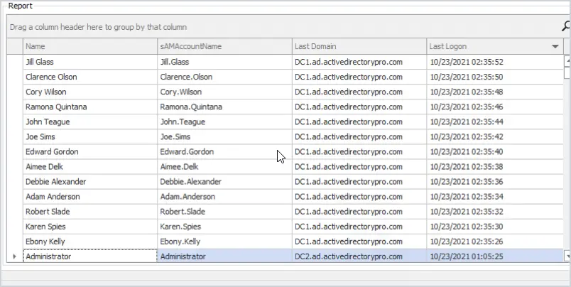
The last logon reporter will get the user’s TRUE last logon time from all domain controllers in your domain. You can limit the search to the entire domain, organizational unit, or groups.
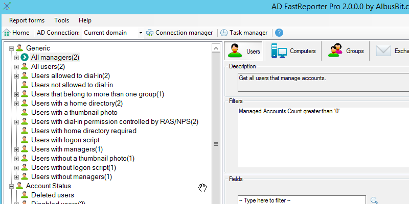
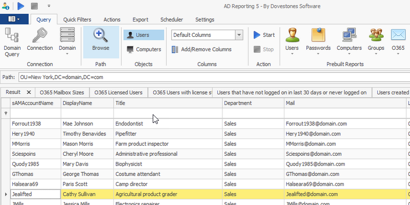
AD FastReporter has a large list of pre-built reports to pick from. Report on users, computers, groups, contacts, printers, group policy objects, and organizational units. Very easy to use but does have an older style interface.
Here is a small example of the reports you can run:
All users
Deleted Users
Users with a home directory
users without logon script
All computers
All domain controllers
Computers created in the last 30 days
Users created in the last 30 days
13. Local Group Report
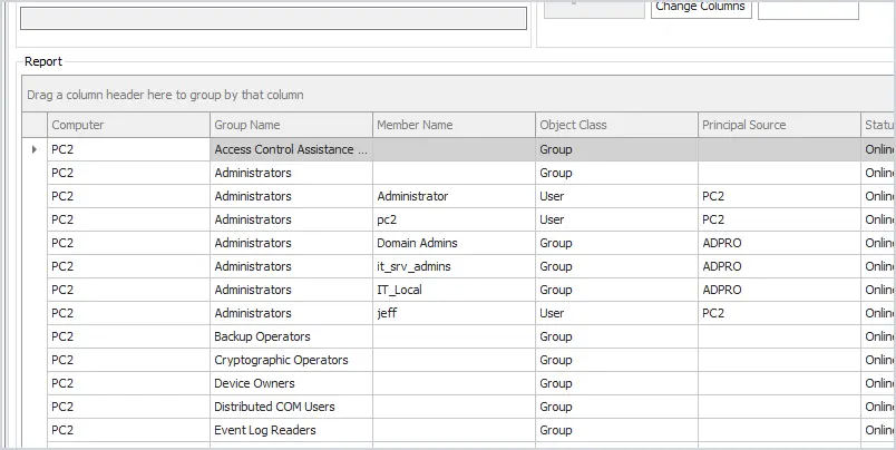
This tool gets the local groups and group members on remote computers. You can quickly sort or filter the groups to get a list of all users and groups that have local administrator rights.
Report and export group membership has never been easier, select from the entire domain, groups, or organizational unit. This tool also helps to find nested security groups.
Key Features
The fastest way to get all domain gruops and group membership
Dovestones AD Reporting tool contains a large number of pre built reports. You can customize the report by selecting user attributes and defining which users to export.
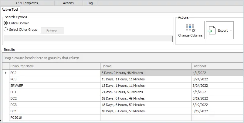
Get the uptime and last boot of remote computers. Report on the entire domain or select from an OU or group.
Very helpful during maintenance days to verify if computers have rebooted.
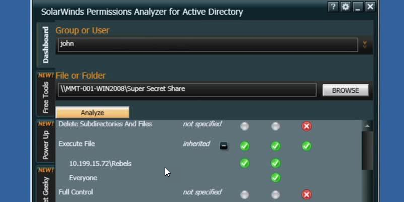
17. SolarWinds Permissions Analyzer
This FREE tool lets you get instant visibility into user and group permissions. Quickly check user or group permissions for files, network, and folder shares.
Analyze user permissions based on an individual user or group membership.
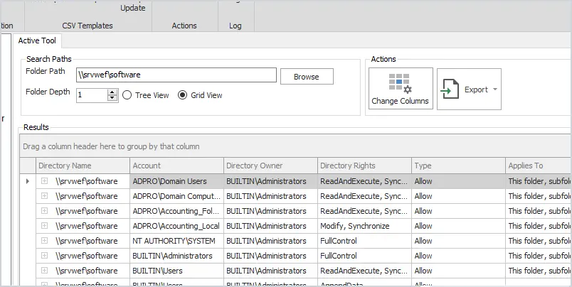
The NTFS permissions tool will report folder security for local, remote, and UNC folder permissions. The grid view comes with a powerful filter so you can search and limit the results to find specific permissions such as Active Directory groups.
Windows PowerShell is a very powerful tool that can automate many Active Directory and Windows tasks. The problem is it can be complex to learn some of the advanced functions. With that said there are plenty of cmdlets that can be used in a single line of code to do some pretty cool things in Windows.
Create new user account: New-Aduser
Create computer account: New-ADComputer
Create a security group: New-ADGroup
Create a organizational unit: New-ADOrganizationalUnit
Get domain details: Get-ADDomin
Get domain password policy: Get-ADDefaultDomainPasswordPolicy
Get group policy: get-GPO -all
Get all services: get-service
Find locked user accounts: Search-ADAccount -LockedOut
The Sysinternals is a suite of small GUI programs and command line utilities designed to troubleshoot and diagnose your Windows systems and applications. They are all portable, which means you don’t need to install them, you can just run the exe or commands with no installation required.
These utilities were created way back in 1996 by Mark Russinovich and then later acquired by Microsoft. There are a bunch of tools included I will list some of the popular ones.
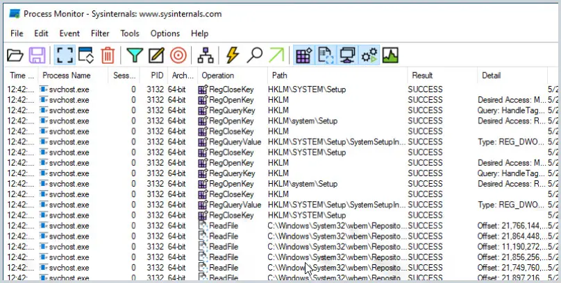
Process Monitor – Shows real time file system, registry and process activity.
PsExec – Lets you execute programs on a remote system
PsKill – Kill local and remote processes
Sysmon – Logs system activity about process creations, network connection and changes to files
Psinfo – Shows info about a local or remote computer
All-in-one Active Directory Toolkit
Our AD Pro Toolkit includes 12 Active Directory tools in a single interface.
The main benefit is it will save you time and make managing Active Directory easier. One of the most popular tasks of working with Active Directory is to create new user accounts. The built-in tools provide no options for bulk importing new accounts so it becomes very time-consuming. With the AD Pro Toolkit you can easily bulk import, bulk update, and disable user accounts.
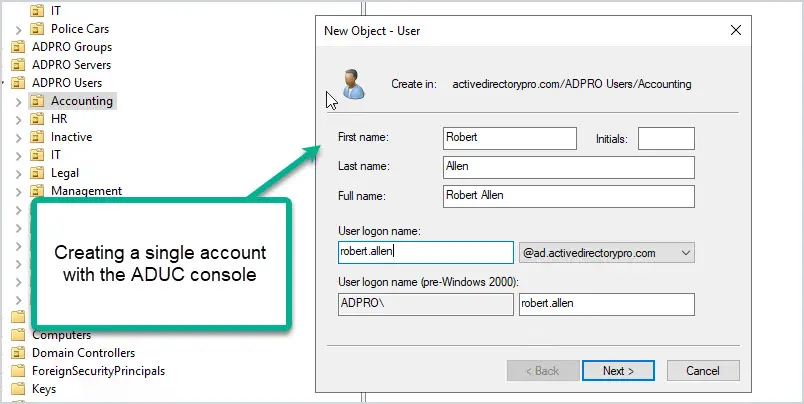
Below is a picture of how you would create an account with the built-in (ADUC) Active Directory Users and Computers console. Everything has to be manually entered and you have to go back and add users to groups.
Using Active Directory tools like the AD Bulk Import tool, you can bulk import thousands of accounts at once. Plus you can automatically set user accounts fields and add users to groups. Let me show you how easy it is.
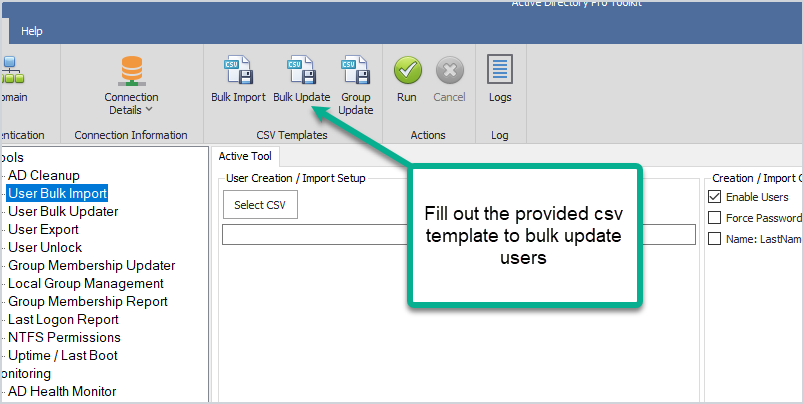
Step 1: Fill out the provided CSV template.
The template includes all the common user fields you need to create a new account. Just fill out what you need and save the file.
Step 2: Import new account
With this tool just select your CSV file and click run. This will import all of the account information from the CSV and automatically bulk create new Active Directory user accounts.
You can watch the import process and when complete you have a log file of the import.
You will at some point be asked to export users to a CSV and again there is no easy built in option for this. When I was an administrator at a large organization I would get this request at least once a week and it was a pain. When I developed the user export tool this process became so easy I was able to have other staff members take it over.
The above picture is from the user export tool. This tool lets you easily export all users from the entire domain, an OU, or a group.
The ease of use is another benefit as many people don’t have time to learn PowerShell. PowerShell is a great tool and can do many things but it can be complex and time-consuming to learn. The AD Pro Toolkit has a very simple interface and you can start using it right away to perform many advanced tasks in your domain.
Frequently Asked Questions
Below are questions and answers regarding the AD Pro Toolkit.
Does the AD Pro Tool support multiple domains?
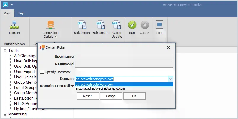
Yes. It will auto-detect your domains based on current credentials. You can click the domain button to change authentication and connect to other domains or domain controllers.
Do you have a tool to help with account lockouts?
Yes, the user unlock tool can quickly display all locked users and the source of the lockout.
What is required to use the toolkit?
To create and bulk modify users you will need these rights in your Active Directory domain. This is often done by putting your account in the domain administrator group but can also be done by delegating these rights. Some tools like the last logon reporter, export, and group membership require no special permissions.
Do I need to know PowerShell or scripting?
No. All tools are very easy to use and require no scripting or PowerShell experience.
Is there a way to bulk update the manager, telephone numbers, and other user fields?
Yes, this is exactly what the bulk updater tool was created for. You can easily bulk update from a large list of user fields.
Can I bulk export or import on a scheduled task?
We are working on this right now. AD Cleanup, bulk import, update, and export tools will include an option to run on a scheduled task or from a script.
I was just hired and Active Directory is a mess. Can the Pro toolkit help?
The AD Cleanup tool can help you find old user and computer accounts and bulk disable or move them. We have many customers that use this tool to cleanup their domain environments.
In this guide, I will demonstrate how to deploy a domain controller in Azure.
Deploying a Domain Controller in Azure can be used to add additional Domain Controllers to your on-premises environment. It’s also an easy way to create an Active Directory test lab.
Note: The VM I create in this demo is for testing, the settings are not optimal for a production domain controller. If you want to deploy a Domain Controller in Azure for production you will need to determine the right settings for your organization, such as VM size (CPU, Mem), redundancy options, disks, and network settings, all of which will increase the cost.
Tip #1: For a production DC, DO NOT give it a public IP or allow public inbound ports.
Tip #2: To add an azure domain controller to your on-premises environment you will need a VPN tunnel from your network to Azure. I will go over this in a separate guide.
Tip #3: For production, the Azure virtual network must not overlap your on-premises network. For testing, it doesn’t matter (assuming you will not be connecting to your on-premises network).
Let’s get started.
Part 1: Create a Virtual Machine
If you don’t have an Azure account you can create one for free. Microsoft gives you a $200 Azure credit for 30 days. This is plenty of credits to create several VMs and use other Azure resources.
Step 3. Click on Create and select “Azure virtual machine”
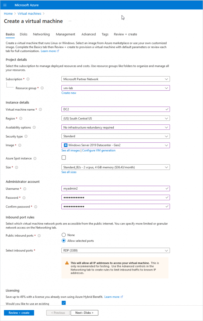
Step 4. Enter basic information for the new VM
Subscription: Select the subscription you want to use for the VM.
Resource group: Select an existing or create a new resource group.
Virtual machine name: Give your VM a name.
Region: Choose your region, you typically want a region that is close to you.
Availability options: This is for redundancy and will ensure your VMs are still running if one Azure data center has a failure. You want this for production VMs. I’m just creating a test VM so I’ll choose “No infrastructure redundancy required.”
Security Type: I’ll choose Standard.
Image: Pick the OS you want to use, I’ll pick “Windows Server 2019 Datacenter”.
Size: You will need to determine the size of VM you need. For testing reasons, I’ll choose a small VM to keep costs low.
Username and password: This will be the administrator account for the VM.
Public inbound ports: For production, you want this set to “none”. For testing, I’ll leave RDP open.
Licensing: If you have anexisting license you can use select the box, this can save money on each VM.
Here is a screenshot of the Basics settings for my VM.
Now click Next to go to the Disks page.
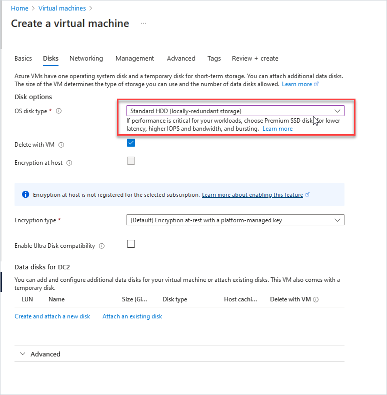
Step 5. Enter disk details for the VM.
Determine the disk type to use, for testing I use the standard HDD.
Click next to go to networking.
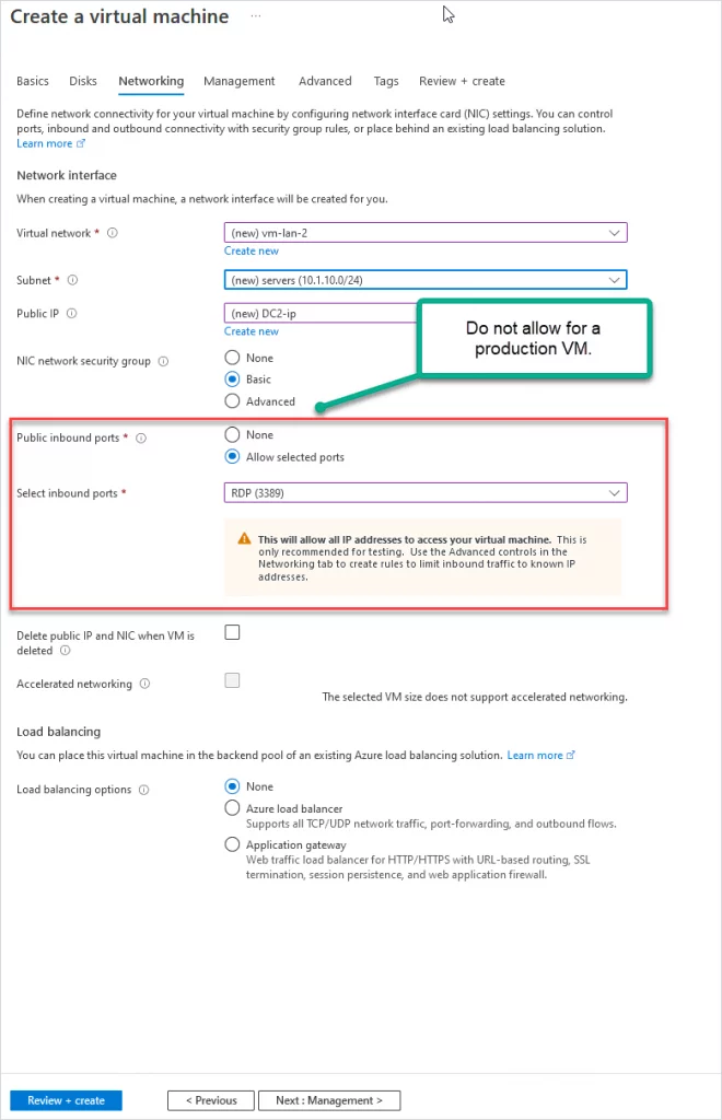
Step 6. Network settings
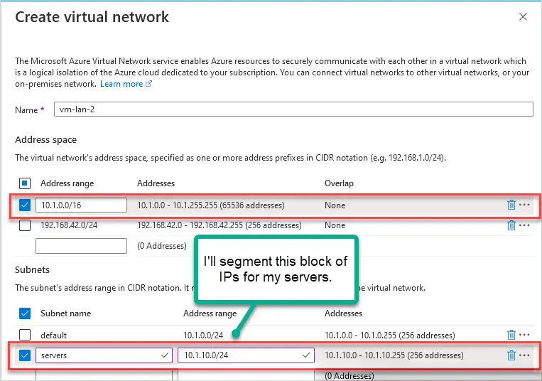
Virtual network: Select an existing or create a new virtual network.
Subnet: Select or create a subnet.
You create a virtual network and then use subnetting to segment the address space. For example, I’m using the 10.1.0.0/16 address space then I segment 10.1.10.0/24 (256 addresses) with subnetting. I’ll use the 10.1.10.0/24 subnet block for my servers.
Public IP: A public IP will be added automatically. For testing, this is OK, for production set this to none.
NIC network security group: This is s stateful firewall for your virtual network. I’ll choose standard.
Public inbound ports: For production, you want to select none. For testing, you can use RDP to access the VM.
Click next to “Management”
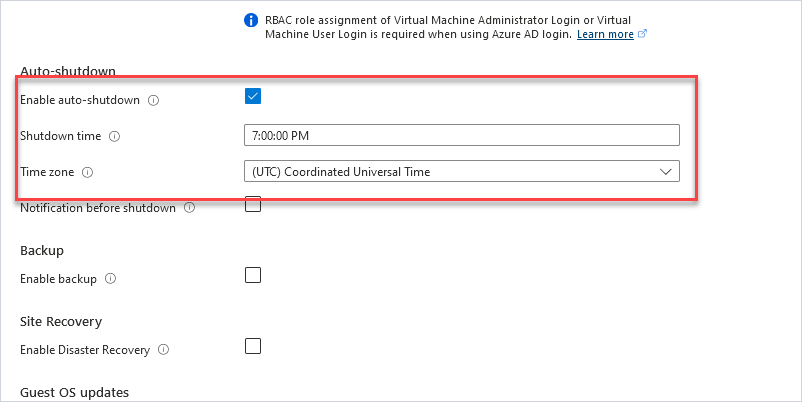
Step 7: Management Settings
The only thing I want to point out on this page is the “Auto-shutdown” option. For testing with Azure, this is a great feature to help save costs. You get charged for the VM running even if you are not using it. I’m not going to be using this test domain controller 24/7 so I’ll have it auto shut down at 7:00 PM each night. Do not do this for a production domain controller.
Step 8: Click Review + create
Microsoft will validate your settings and show any warnings or settings that were missed. You will also get a cost estimate but keep in mind it is just an estimate.
When ready click the “Create” button to create the VM.
You will get a progress page so you can watch the status of the deployment. It took about 5 minutes for my VM to be created.
Part 2: Configure VM with Static IP Addresses
Domain controllers need a static IP address and the DNS pointing to itself. For on-premises DCs you would just go into the NIC settings and manually configure the IP settings. With Azure VMs it’s recommended to set this at the Virtual Network Interface.
Go to VM Networking settings.
In the right-hand menu for your VM under settings click on “Networking”.
Now click on the Network Interface for the VM (You will have a different name).
Next click on “IP Configurations” in the left menu under settings.
Next click on “ipconfig1” under IP configurations.
Change the IP from “Dynamic” to “Static” and enter the IP address you want the domain controller to have, it must be an IP from the subnet you assigned to your virtual network. I’ll give my DC the IP address 10.1.10.10.
Click “Save”. The network interface will be restarted to set the IP address.
Go back to the Network Interface and click on “DNS servers”.
Set the DNS server to the IP address of the domain controller.
Now on the VM, your server should be configured with the settings from above. Below I run ipconfig /all to verify my IP settings.
Part 3: Install Active Directory Domain Services
With a VM created and the IP settings configured we can move forward with installing Active Directory on the server. If you have installed ADDS before this is not new, it’s the same as installing it on an on-premises server.
Go to the server manager and click on “Add roles and features”
Before you begin – click “Next”.
Installation type – select “role based” and click “Next”.
Server Selection – select the hostname of your server and click “Next”.
Server Roles – select “Active Directory Domain Services”.
You will get a pop-up to add additional features. Click “Add Features”.
Click “Next”.
Features – no features need to be added so click “Next”.
AD DS – Click “Next”.
Confirmation – Click “Install”.
The installation will start.
When finished click the yellow icon in the upper right corner and click on “Promote this server to a domain controller”.
Deployment Configuration
I’m creating a new domain so I’m going to pick “Add a new forest”. If you’re adding another DC to your existing domain you would pick the first option “Add a domain controller to an existing domain”.
Domain Controller Options
For a new test domain, the default settings are good. Add a DSRM password and click next.
DNS Options
Click next on this screen.
Additional Options
Enter a NetBIOS name and click “Next”
Paths
I always leave these as default settings
Review Options
Review your settings and click “Next”
Prerequisites Check
If the Prerequisites pass click on “Install”
When done installing the server will reboot and will now be a domain controller.
Nice work. If you followed along you should now have a domain controller running in the Azure cloud.
You can now deploy additional Azure VMs and connect them to this domain controller. You can also use this domain controller to add additional DCs to your on-premises environment.
Part 4: Additional Settings and Tips
Here are a few additional settings and tips I recommend.
You will need to create a new site in Active Directory Sites & Services with the new subnet.
You should adjust the domain controller DNS settings for redundancy.
A VPN tunnel is required from your on-premises network to Azure.
If you are testing and use a public IP with open ports (RDP 3389), then I recommend using fake/dummy data in Active Directory. Their server might get comprised due to the internet exposure so don’t use real data such as real usernames and passwords.
You can use the Azure firewall to limit access to the VM from your IP address.
Use Bastion for secure remote connectivity.
Explore the many options that Azure has to offer, it’s very impressive everything it has to offer.
Do you plan to use domain controllers running in Azure? Let me know in the comments below.
Recommended Tool: Permissions Analyzer for Active Directory
This FREE tool lets you get instant visibility into user and group permissions and allows you to quickly check user or group permissions for files, network, and folder shares.
You can analyze user permissions based on an individual user or group membership.
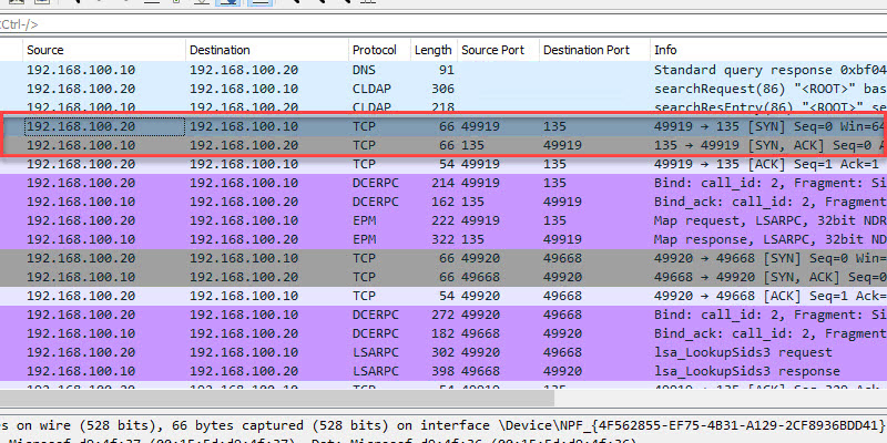
Description: Port 135 is a critical client/server port. This port is used by many Microsoft services and should not be blocked by a firewall. First the client connects to the RPC mapper service (port 135) and asks the mapper what port a given service is listening on (which will be a dynamic port range… see below). The RPC mapper responds to the client with the port and then the client connects to that port. You can see this in the above screenshot.
Firewall: Allow between client and server. Port 135 should not be exposed to the internet.
TCP/UDP 49152 – 65535 RPC Dynamic Ports
Description: The dynamic port range is used by various server applications. RPC dynamic port allocation instructs the RPC program to use a particular random port in the range configured for TCP and UDP, based on the implementation of the operating system used. The RPC mapper (port 135) is used to connect clients to services running on these dynamic ports.
Firewall: Allow between client and server. This port range should not be exposed to the internet.
we recommend that you reconfigure the firewalls to allow traffic between servers in the dynamic port range of 49152 through 65535. This range is in addition to well-known ports that are used by services and applications.
Description: Kerberos is an authentication protocol that authenticates requests between a client and server in a secure manner. This is Microsoft Window’s default authentication method for domain-joined devices.
Firewall: Allow between client and server. Port should not be exposed to the internet.
TCP 389 LDAP
Description: LDAP is a directory access protocol. This protocol is used to search, add/delete, authenticate and modify data in a Directory Server such as Active Directory.
Firewall: Allow between client and server. Port should not be exposed to the internet.
UDP 53 DNS
Description: DNS is a critical service used to map IP addresses to host names. This is a critical service used by clients to locate resource records in the domain and lookup external domain names.
Firewall: Allow between client and server. If DNS is running on your Active Directory server I do not recommend exposing it to the internet.
TCP 445 SMB
Description: Server message blocks (SMB protocol) is a client-to-server communication protocol used for accessing files, printers, and data on a network. This port is used during startup to get GPO information, it is also used when running the gpupdate command.
Firewall: Allow between client and server. Do not expose this port to the internet.
Ports Used When a User Logs into a Domain-Joined Computer
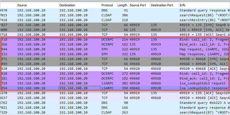
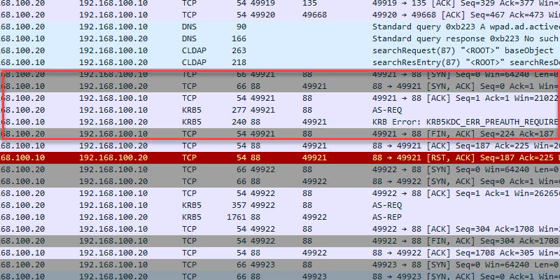
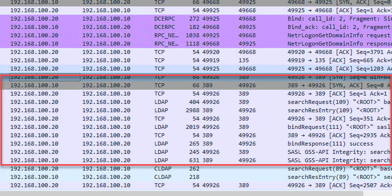
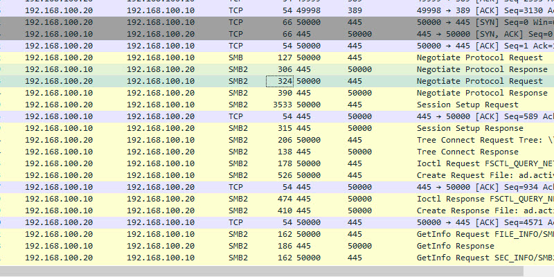
In this example, I will log into computer PC1 (192.168.100.20) and capture the network packets from the domain controller.
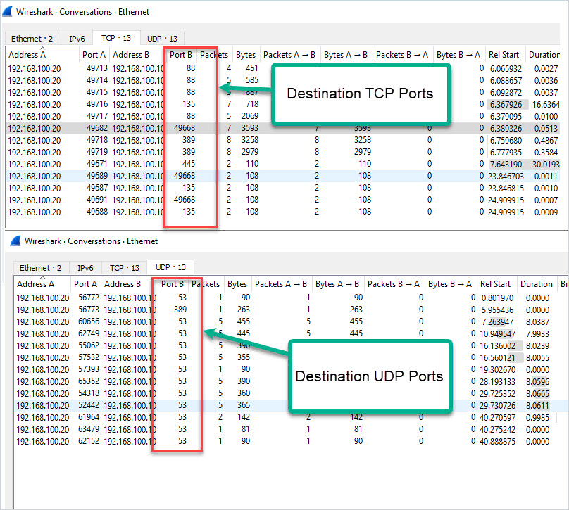
Here is a conversation view of the TCP/UDP ports used. This is traffic sent from the client to the domain controller and destination ports.
Here is a summary of the destination ports used by the client.
TCP 88 (Kerberos)
TCP 135 (Microsoft RPC)
TCP 389 (LDAP)
TCP 445 (Microsoft DS)
TCP 49668 (RPC for LSA, SAM, NetLogon) – This starts with a request to port 135
UDP 53 (DNS)
UDP 389 (LDAP)
Ports Used When Running Gpupdate
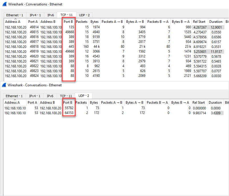
While logged into the client PC I will run the gpupdate command to see what ports are used.
Results below. It Looks like TCP port 445 is used the most when running a gpupdate.
Ports Used When Joining a Computer to The Domain
This looked similar to the other packet captures.
TCP 88 (Kerberos) TCP 135 (Microsoft RPC) TCP 389 (LDAP) TCP 445 (Microsoft DS) TCP 49668 (RPC for LSA, SAM, NetLogon) – This starts with a request to port 135 UDP 53 (DNS)
Ports Used When Rebooting
Nothing new, I see the same ports used when compared to the other packet captures.
Hopefully, this guide helps you to understand the ports used between a client and an Active Directory server. Keep in mind this test was a default domain controller install with no additional services running, the more services you install the more ports that may be used.
Recommended Tool: Permissions Analyzer for Active Directory
This FREE tool lets you get instant visibility into user and group permissions and allows you to quickly check user or group permissions for files, network, and folder shares.
You can analyze user permissions based on an individual user or group membership.
In this post, I will demonstrate how to change the IP address on a domain controller.
Before you change the IP address it is very important to run through a checklist. Any changes to a domain controller can disrupt services and impact business operations. See my checklist below.
For this demonstration, I have the following settings.
DC1, IP Address 192.168.100.10
DC2, IP Address 192.168.100.11
DC3, IP Address 192.168.100.12
I’m going to change the IP on DC2 to 192.168.100.15. If you are changing to a different subnet there are additional things to consider that I go over in the checklist.
Pre-Change Checklist
I recommend reviewing each item on this checklist before making changes. I’ve migrated many domain controllers from small to large networks and these steps have been a lifesaver. If you do this often you will probably come up with your own checklist.
Do You Have Multiple Domain Controllers?
It is best practice to have multiple domain controllers and backup Active Directory for disaster recovery reasons. I do not recommend making major changes to domain controllers if you have a single domain controller. If you have multiple DCs and the change breaks the server you can still operate from a secondary DC.
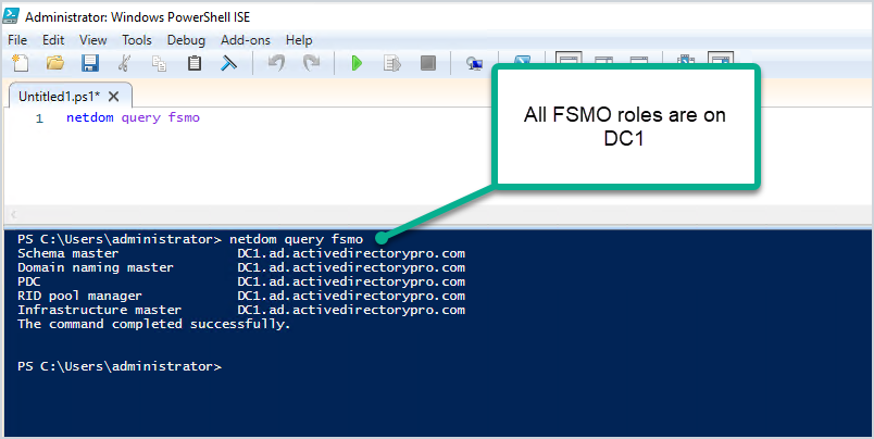
Does the DC hold any FSMO roles? Easily check with this command:
netdom query fsmo
Below you can see all my FSMO roles are on DC1.
To help avoid disruption to authentication services you could move the FSMO roles to another domain controller that is on the same site. Keep in mind you would need to move any services that are manually configured to the server.
I’m making changes to DC2 which has no FSMO roles running on it.
Check Installed Roles and Features
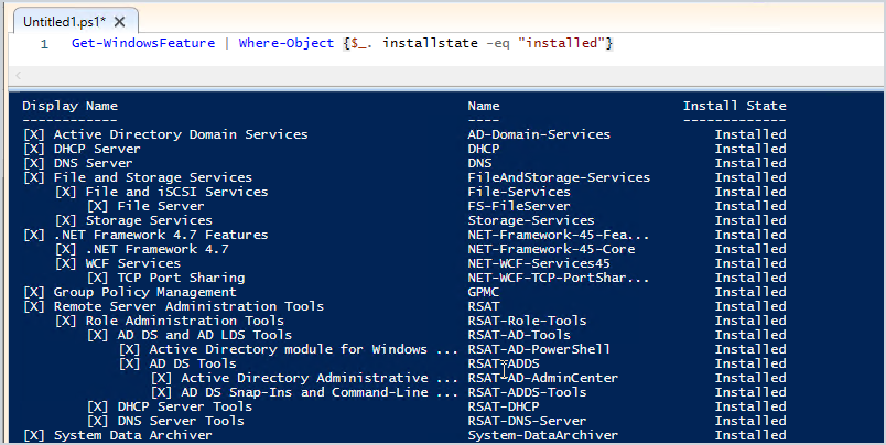
I recommend checking what services are running on the server, you don’t want to change the IP and then have something break because you didn’t know it was a DHCP server or a web server.
Check the control panel for installed software
Check the installed roles and features
You can quickly check the installed roles and features with this command:
Below you can see my DC2 server has some critical services running on it including DHCP and DNS. I’ll need to consider this when changing IP addresses.
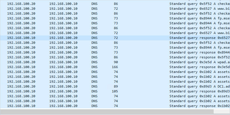
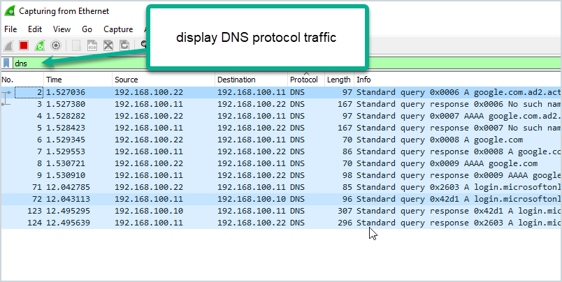
Find Devices Pointing to the Domain Controller with Wireshark
Wireshark can help you identify what systems are pointing to your domain controller for various services like DNS, DHCP, and so on. This might be the most important pre-change step.
Useful Wireshark filters:
dns
dhcp
ldap
DCERPC
Here is an example:
The packet capture shows that system 192.168.100.22 is using DC2 for DNS. I’ve done a large migration of domain controllers before and used Wireshark to help identify systems that are still pointing to old domain controllers. From experience, you will probably be surprised at how many systems are hardcoded to your DCS.
Check Domain Controller Health
You need to check that your domain controller is healthy before making the change. Any issues could result in replication issues, DNS issues, and so on. I’ve got a complete guide on how to use dcdiag its actually very easy to use. Just open the command prompt on your server and run the command.
dcdiag
Check The Health of DNS
By default, dcdiag does not test DNS. Use this command to run a complete test on DNS.
dcdiag /test:dns /v
Make sure the server passes all tests and the name resolution SRV record is registered.
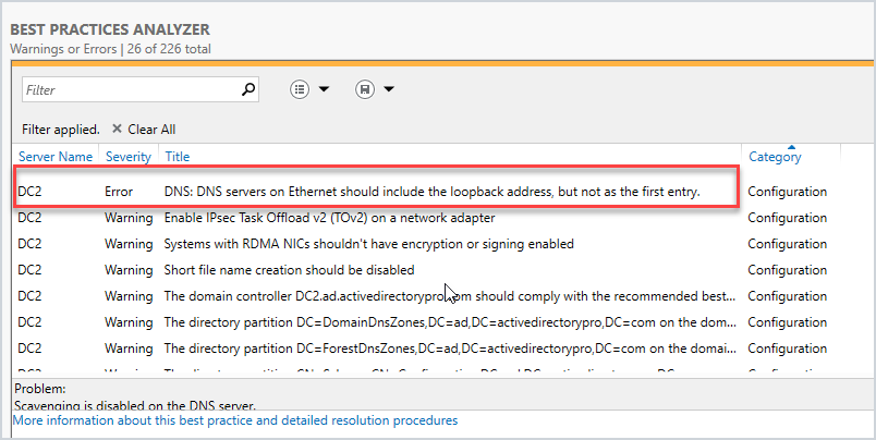
Run Best Practice Analyzer
The best practice analyzer can find configuration issues according to Microsoft best practices. The BPA tool is not always accurate so you need to double check its findings. Also, any errors or warnings do not mean your migration will fail. It can just help you find any major misconfigurations according to Microsoft best practices.
Here is a scan from my DC2.
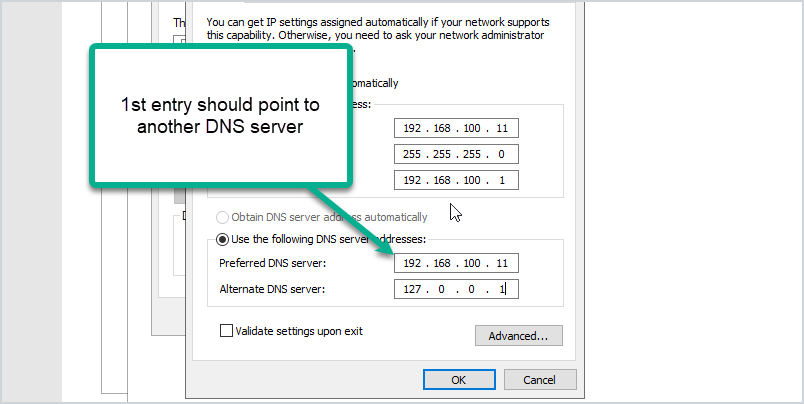
I’ve got a warning that the loopback address is not included on the ethernet adapter settings. The best practice is to point the preferred DNS server to another DNS server (not itself).
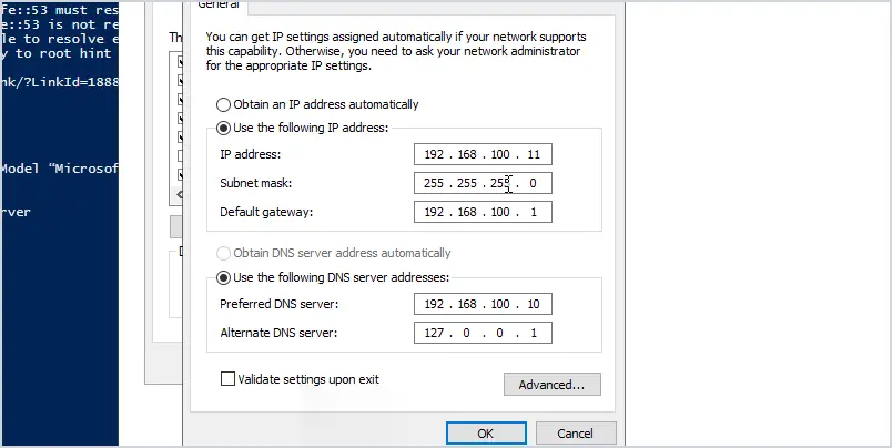
Here is an example of how it should be configured:
My DC2 IP address is 192.168.100.11. You can see I set the preferred DNS to another domain controller (DC1) and the alternate is set to the loopback address. This is Microsoft’s best practice.
Again any warnings or errors the best practice analyzer finds doesn’t mean your migration will fail. But to help avoid any potential migration issues I recommend running this tool and reviewing the scan results. It might even fix some issues you weren’t aware of.
Are You Changing Subnets?
If you will be changing to a new subnet then consider the following:
If the server also runs DHCP you will need to update the helper address on your switch or firewall.
Add the new subnet to Active Directory sites and services.
Check Firewall Rules
Are there any firewall rules that will need to be updated? This could be your network firewall and windows based firewalls. I typically have rules on the network firewall that limit network access for critical servers like domain controllers. I would need to update the firewall rules to permit traffic to the new DC IP.
Plan & Schedule the IP Change
I recommend making this type of change during your maintenance window. No matter how much you prepare for changes there is always a potential for something going wrong. You need to have a maintenance window to allow time to resolve any issues. Don’t forget to communicate these changes with your team ahead of time.
How to Change the IP Address of a Domain Controller:
Here are the steps to changing the IP Address on a domain controller.
Log on locally to the server (console access, don’t RDP or use remote access).
Change NIC TCP/IP settings
Change IP Address
Change subnet mask (if required)
Change Default gateway (if required)
Preferred DNS server (should point to another DC in the same site)
Alternate DNS server (should be the loopback address 127.0.0.1)
After changing the IP run ipconfig /flushdns to remove local cache
Run ipconfig /registerdns to ensure the new IP is registered by the DNS server
Run dcdiag /fix to ensure service records are registered.
Update DHCP settings if DC server is also DNS server
If subnet address changed then make sure AD Sites and services is updated
Update clients that use static ip address
Update other DCs nic settings (if needed)
Run commands dcdiag and dcdiag /test:dns /v to check for issues.
Verify DNS is working, you can do this with nslookup.
Test authenticating to the DC. You can do this by manually settings a client IP DNS settings to the IP of the DC or using PowerShell and specify the authentication server.
Continue to monitor old IP with wireshark – This can be done by a span port or assign the DCs old IP to a computer with wireshark installed. This is useful to help find systems that are still using the old IP of the DC.
Update firewall rules if needed.
If a client system is having issues try to flush the local dns cache with ipconfig /flushdns command
Changing the IP address on the DC should not effect any shares on the server as long as DNS is updated.
Summary
In this post, I showed you how to change the IP address on a domain controller. I also showed you a checklist I go through before changing the IP address. Authentication, DNS, and DHCP services are critical so it’s very important to plan and review as much as you can before making changes to these critical services. Also, all organizations and networks are different so over time you may have a different checklist than mine.
Recommended Tool: Permissions Analyzer for Active Directory
This FREE tool lets you get instant visibility into user and group permissions and allows you to quickly check user or group permissions for files, network, and folder shares.
You can analyze user permissions based on an individual user or group membership.