As cyber threats continue to evolve, security professionals require reliable tools to defend against security vulnerabilities, protect sensitive data, and maintain network security. Open source cyber security tools provide a cost-effective solution for individuals and organizations to combat these threats on-premises and with cloud security and mobile devices. Let’s consider the top 25 open-source cyber security monitoring tools in 2023 that help ensure continuous network and system performance monitoring.
Table of contents
- What are the Top Cybersecurity Threats Today?
- Benefits of Open-Source CyberSecurity tools
- Top 25 Open Source Cyber Security Monitoring Tools in 2023
- 1. Wireshark: Network Protocol Analyzer
- 2. Snort: Network Intrusion Detection and Prevention System
- 3. OSSEC: Host-Based Intrusion Detection System
- 4. Security Onion: Intrusion Detection and Network Security Monitoring Distribution
- 5. Nmap: Network Scanning and Discovery Tool
- 6. Kismet: Wireless Network Detector, Sniffer, and Intrusion Detection System
- 7. Suricata: High-Performance Network Intrusion Detection and Prevention Engine
- 8. Zeek (formerly Bro): Network Analysis Framework for Security Monitoring
- 9. OpenVAS: Vulnerability Scanning and Management Solution
- 10. ClamAV: Open-Source Antivirus Engine
- 11. Fail2Ban: Log-Parsing Application to Protect Against Brute-Force Attacks
- 12. AlienVault OSSIM: Open-Source Security Information and Event Management Platform
- 13. Cuckoo Sandbox: Automated Malware Analysis System
- 14. Logstash: Log Processing and Management Tool
- 15. pfSense: Open-Source Firewall and Router Distribution
- 16. ModSecurity: Open-Source Web Application Firewall
- 17. AIDE (Advanced Intrusion Detection Environment): File and Directory Integrity Checker
- 18. Graylog: Open-Source Log Management Platform
- 19. Wazuh: Security Monitoring and Compliance Solution
- 20. T-Pot: Honeypot Platform
- Honorable mentions
- Tips to Improve Your Cybersecurity Posture
- Frequently Asked Questions (FAQs)
- Wrapping up
- Other posts you may enjoy
What are the Top Cybersecurity Threats Today?
As cyber threats continue to evolve and become more sophisticated, organizations must stay informed and prepared to defend against a wide range of security risks.
Here are the top cybersecurity threats that businesses and individuals should be aware of today:
1. Phishing Attacks: Phishing attacks are a prevalent form of social engineering where cybercriminals use deceptive emails or websites to trick users into revealing sensitive information or installing malware. These attacks often target login credentials, financial information, and other personal data.

2. Ransomware: Ransomware is a type of malicious software that encrypts a victim’s files or locks their systems, demanding a ransom payment to restore access. Ransomware attacks can cause significant financial losses and operational disruptions for organizations.
3. Insider Threats: Insider threats refer to security risks posed by employees, contractors, or other individuals with authorized access to an organization’s systems and data. These threats can result from malicious intent or negligence, leading to data breaches or system compromises.
4. Supply Chain Attacks: Also known as third-party attacks or vendor risk, supply chain attacks target an organization’s suppliers, vendors, or partners to gain access to their systems and data. These attacks often exploit security vulnerabilities in the supply chain to compromise multiple organizations.
5. Distributed Denial of Service (DDoS) Attacks: DDoS attacks involve overwhelming a target’s network or system with a flood of traffic, rendering it inaccessible to legitimate users. DDoS attacks can cause severe downtime and service disruptions.
6. Advanced Persistent Threats (APTs): APTs are sophisticated, coordinated cyberattacks by well-funded threat actors or nation-state groups that target specific organizations for espionage, data theft, or sabotage. APTs often use advanced techniques and tactics to evade detection and maintain a long-term presence within a target’s network.
7. Zero-Day Exploits: Zero-day exploits are attacks that take advantage of previously unknown security vulnerabilities in software or systems. These vulnerabilities, also known as zero-day flaws, have no existing patches or fixes, making them particularly dangerous and challenging to defend against.
8. Internet of Things (IoT) Security: The increasing adoption of IoT devices and connected technologies has expanded the attack surface for cybercriminals. IoT devices are often vulnerable to cyber threats due to weak security measures, creating new risks for organizations and consumers.
9. Data Breaches: Data breaches occur when unauthorized individuals gain access to an organization’s sensitive data, such as customer information, financial records, or intellectual property. Data breaches can result in significant financial and reputational damage for organizations.
10. Cloud Security Threats: As more organizations migrate to cloud-based services, cloud security has become a critical concern. Threats in the cloud can arise from misconfigurations, weak authentication mechanisms, and vulnerabilities in cloud applications or infrastructure.
Benefits of Open-Source CyberSecurity tools
Open source cyber security monitoring tools offer numerous advantages over proprietary solutions, making them an attractive option for businesses, organizations, and individuals looking to enhance their security posture and perform effective security testing.
Here are some key benefits of using open-source tools for cyber security monitoring for monitoring services that pose security threats, even if you have another network monitoring system. Proper cybersecurity monitoring and access management are key to maintaining a secure environment.
Cost-Effectiveness
One of the most significant benefits of open-source cyber security tools is their cost-effectiveness. With no licensing fees or subscription costs, these free tools enable security teams to access powerful network monitoring solutions without breaking the bank.
This particularly benefits small businesses and startups with limited budgets, allowing them to allocate resources to other critical areas.
Customizability and Flexibility
Open-source network monitoring tools offer high customizability and flexibility, allowing security professionals to tailor the tools to their specific needs. This adaptability enables organizations to address unique security threats and vulnerabilities, ensuring a more robust security posture.
Additionally, the ability to integrate these tools with existing security infrastructure adds an extra layer of protection to network security.
Rapid Development and Updates
The open-source community is known for its rapid development and frequent updates. As new security threats and vulnerabilities emerge, open-source cyber security tools are often among the first to receive patches and updates.
This continuous monitoring and proactive response help organizations stay ahead of potential security risks and maintain a strong security posture.
Extensive Support and Collaboration
Open-source cyber security tools benefit from an extensive support network, comprising developers, users, and experts from around the world.
This collaborative environment fosters knowledge sharing, allowing security professionals to learn from one another and develop more effective security strategies.
Additionally, the availability of comprehensive documentation and online forums makes it easier for users to troubleshoot issues and enhance their understanding of network monitoring and security.
Improved Security and Transparency
With their source code openly available for inspection, open-source cyber security tools offer greater transparency than proprietary alternatives. This transparency allows security professionals and researchers to scrutinize the code for potential security vulnerabilities and ensure its integrity.
Moreover, the collaborative nature of the open-source community means that any identified issues are addressed quickly, further enhancing the overall security of these tools.
Platform Independence and Interoperability
Open-source network monitoring software often supports a wide range of operating systems, including Windows, macOS, and Linux, allowing organizations to deploy these tools across diverse environments.
This platform independence and interoperability help organizations ensure comprehensive network monitoring, regardless of the underlying infrastructure.
Top 25 Open Source Cyber Security Monitoring Tools in 2023
Note the following free cyber security monitoring tools in 2023 and the open-source list of solutions you can take advantage of and no free trial needed.
1. Wireshark: Network Protocol Analyzer
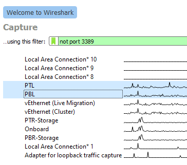
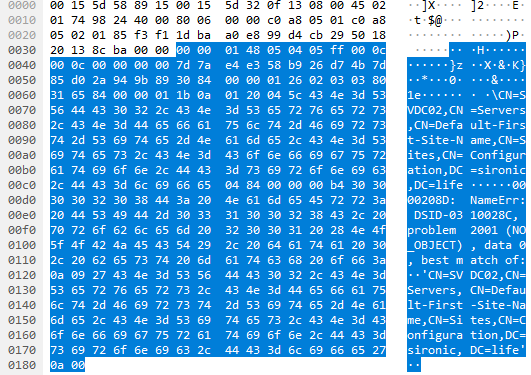
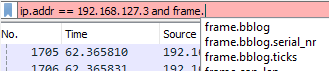
Wireshark is a widely-used network protocol analyzer that enables security teams to troubleshoot, analyze, and monitor network traffic in real-time to detect security issues. It is a defacto standard network monitoring tool.
command line interface data packets open source platform data breaches packet capture web apps network packets computer security experts solarwinds security event manager security scanning

By dissecting network protocols, Wireshark provides valuable insights into potential security risks and network vulnerabilities, allowing professionals to identify and resolve issues efficiently with the Wireshark network monitoring solution.
You can monitor a wide range of protocols, including TCP/IP, simple network management protocol, FTP, and many others. If you are looking for a network monitor this is it.
2. Snort: Network Intrusion Detection and Prevention System
Snort is a powerful open-source intrusion detection and prevention system (IDPS) that monitors network traffic and detects potential security threats.
It provides real-time traffic analysis, packet logging, and alerting capabilities, making it an essential tool for security auditing and network monitoring.

3. OSSEC: Host-Based Intrusion Detection System
OSSEC is a comprehensive host-based intrusion detection system (HIDS) that offers log analysis, file integrity checking, rootkit detection, and more.
It supports various operating systems, including Linux, Windows, and macOS, and helps security professionals monitor and analyze network protocols for potential security vulnerabilities.

4. Security Onion: Intrusion Detection and Network Security Monitoring Distribution
Security Onion is a Linux distribution specifically designed for intrusion detection, network security monitoring, and log management.
With a suite of powerful open-source tools, including Snort, Suricata, and Zeek, Security Onion provides a robust solution for security teams to monitor networks and detect security breaches.

5. Nmap: Network Scanning and Discovery Tool
Nmap is a versatile network scanning and discovery tool that helps security professionals identify network devices, open ports, and running services.
It is an essential network monitoring software for vulnerability management, penetration testing, and network inventory management.

6. Kismet: Wireless Network Detector, Sniffer, and Intrusion Detection System
Kismet is a wi fi security tool that detects, sniffs, and analyzes wireless networks. By monitoring wireless network traffic, Kismet identifies potential security risks, network vulnerabilities, and unauthorized users, making it an invaluable tool for wireless network security.

7. Suricata: High-Performance Network Intrusion Detection and Prevention Engine
Suricata is an open-source, high-performance network intrusion detection and prevention engine that provides real-time network traffic analysis, threat detection, and alerting.
Suricata enables security professionals to maintain network integrity and security by employing advanced threat defense and anomaly detection techniques.

8. Zeek (formerly Bro): Network Analysis Framework for Security Monitoring
Zeek, previously known as Bro, is a powerful network analysis framework that offers real-time insight into network traffic.
With its flexible scripting language and extensible plugin architecture, Zeek provides comprehensive visibility into network activity, enabling security teams to detect and prevent security threats.

9. OpenVAS: Vulnerability Scanning and Management Solution
OpenVAS is a comprehensive vulnerability scanning and management solution that helps security professionals identify, assess, and remediate security vulnerabilities.
With its extensive plugin library, OpenVAS ensures continuous monitoring and up-to-date vulnerability information, making it a critical tool for vulnerability management.

10. ClamAV: Open-Source Antivirus Engine
ClamAV is an open-source antivirus engine that detects trojans, viruses, and other malicious software.
It offers a command-line scanner, a graphical user interface (GUI) for Windows operating system, and integration with mail servers, ensuring that your systems are protected from security threats.

11. Fail2Ban: Log-Parsing Application to Protect Against Brute-Force Attacks
Fail2Ban is a log-parsing application that monitors log files for malicious activity, such as repeated failed login attempts. Fail2Ban bans the offending IP address when a potential attack is detected, effectively protecting your network from brute-force attacks and unauthorized access.

12. AlienVault OSSIM: Open-Source Security Information and Event Management Platform
AlienVault OSSIM is an open-source security information and event management (SIEM) platform that provides real-time event correlation, log analysis, and threat intelligence.
By integrating multiple security tools, OSSIM helps security teams maintain a unified user interface and enhance their overall security posture.

13. Cuckoo Sandbox: Automated Malware Analysis System
Cuckoo Sandbox is an open-source automated malware analysis system that enables security professionals to analyze suspicious files and URLs in a safe, isolated environment.
It provides detailed reports on malware behavior, including network traffic analysis, file system changes, and API traces, helping security teams identify and mitigate security risks.

14. Logstash: Log Processing and Management Tool
Logstash is part of the Elastic Stack (ELK Stack) and offers log processing and management capabilities.
It collects, parses, and stores log data from various sources, making it an essential tool for security professionals to monitor and analyze network activity, detect security breaches, and maintain system performance.

15. pfSense: Open-Source Firewall and Router Distribution
pfSense is an open-source firewall and router distribution based on FreeBSD. It offers a powerful and flexible network security, traffic shaping, and VPN connectivity solution.
With its extensive features and customization options, pfSense is ideal for securing web servers and internal networks.

16. ModSecurity: Open-Source Web Application Firewall
ModSecurity is an open-source web application firewall (WAF) providing real-time security monitoring and access control. It detects and prevents web attacks, protects sensitive data, and helps security professionals maintain compliance with industry standards and regulations.

17. AIDE (Advanced Intrusion Detection Environment): File and Directory Integrity Checker
AIDE is a file and directory integrity checker that monitors system files for unauthorized changes. It detects modifications, deletions, and additions, allowing security teams to maintain system integrity and prevent security breaches.
18. Graylog: Open-Source Log Management Platform
Graylog is an open-source log management platform that centralizes and analyzes log data from various sources.
Graylog helps security professionals detect security threats, identify network vulnerabilities, and maintain network security by providing comprehensive visibility into network activity.

19. Wazuh: Security Monitoring and Compliance Solution
Wazuh is a free, open-source security monitoring and compliance solution that integrates host-based and network-based intrusion detection systems, file integrity monitoring and security policy enforcement.
Wazuh’s centralized management and powerful analytics capabilities make it an essential tool for security teams to detect and respond to security threats.

20. T-Pot: Honeypot Platform
T-Pot is a platform combining multiple honeypots into a single, easy-to-deploy solution for cyber security monitoring. By simulating vulnerable systems and services, T-Pot attracts attackers and collects threat data, providing valuable insights into current attack trends and techniques.

Honorable mentions
Samhain: Host-Based Intrusion Detection System
Samhain is a host-based intrusion detection system (HIDS) that provides file integrity checking and log file monitoring. It detects unauthorized modifications, deletions, and additions, helping security professionals maintain system integrity and prevent security breaches.
SELKS: Network Security Management ISO with Suricata
SELKS is a live and installable network security management ISO based on Debian, focusing on a complete and ready-to-use Suricata IDS/IPS ecosystem. It offers a user-friendly interface and powerful analytics tools, making it an ideal choice for security teams to monitor networks and detect potential security threats.
Squid: Open-Source Web Proxy Cache and Forward Proxy
Squid is an open-source web proxy cache and forward proxy that improves web performance and security. By caching frequently-requested web content and filtering web traffic, Squid helps reduce bandwidth usage, enhance user privacy, and protect against web-based security threats.
YARA: Pattern-Matching Tool for Malware Researchers
YARA is a pattern-matching tool designed for malware researchers to identify and classify malware samples. By creating custom rules and signatures, YARA enables security professionals to detect and analyze malicious software, enhancing their understanding of current malware trends and techniques.
Arkime (formerly Moloch): Large-Scale, Open-Source, Indexed Packet Capture and Search System
Arkime is a large-scale, open-source, indexed packet capture and search system that provides comprehensive visibility into network traffic. It enables security professionals to analyze network protocols, detect security vulnerabilities, and identify potential security threats, making it an essential tool for network monitoring and security auditing.
Tips to Improve Your Cybersecurity Posture
Improving your cybersecurity posture is essential for safeguarding your organization from various cyber threats. Here are some practical tips to help enhance your cybersecurity defenses:
- Implement Regular Security Audits: Conducting routine security audits can help identify potential weaknesses in your organization’s cybersecurity infrastructure.
- This includes checking for outdated software, misconfigured settings, and other vulnerabilities that may expose your systems to attacks.
- Keep Software and Systems Updated: Regularly update your software, operating systems, and firmware to protect against known vulnerabilities and exploits.
- This includes applying security patches and updates as soon as they become available.
- Use Strong Authentication Mechanisms: Implement multi-factor authentication (MFA) for all critical systems and applications.
- MFA adds an extra layer of security by requiring users to provide additional verification, such as a one-time code or biometric authentication, in addition to their password.
- Encrypt Sensitive Data: Encrypt sensitive data both in transit and at rest to prevent unauthorized access. This includes using secure communication protocols, such as HTTPS and TLS, and implementing encryption solutions for data storage.
- Establish a Strong Password Policy: Enforce a robust password policy that requires users to create complex, unique passwords and update them regularly. Additionally, consider using a password manager to help users manage and store their passwords securely.
- Educate Employees on Cybersecurity Best Practices: Provide ongoing security awareness training to educate employees about common cyber threats, safe online practices, and how to recognize and report potential security incidents.
- Implement Network Segmentation: Divide your network into smaller segments, isolating critical systems and data from less secure areas. This can help prevent the spread of malware and limit the damage in case of a security breach.
- Regularly Backup Important Data: Regularly back up essential data and store copies offsite or in the cloud. This ensures that you can quickly recover from data loss or ransomware attacks.
- Utilize Endpoint Security Solutions: Deploy comprehensive endpoint security solutions to protect devices connected to your network.
- This includes antivirus software, firewalls, intrusion detection and prevention systems, and device management tools.
- Monitor and Analyze Network Traffic: Use network monitoring tools to analyze network traffic, detect anomalies, and identify potential security threats. Regular monitoring can help detect and respond to security incidents more effectively.
- Develop a Cybersecurity Incident Response Plan: Create a detailed incident response plan outlining the steps to take in a security breach. Regularly review and update the plan, and ensure that all employees are familiar with the procedures.
- Collaborate with Security Professionals: Engage with cybersecurity experts or managed service providers to help develop and maintain a strong security posture.
- This can provide access to specialized knowledge and resources to stay up-to-date with the latest threats and best practices.
Frequently Asked Questions (FAQs)
1. What are the best open-source cyber security monitoring tools available in 2023?
This blog post covers the top 25 open-source cyber security monitoring tools in 2023, including Wireshark, Snort, OSSEC, Security Onion, Nmap, Kismet, Suricata, Zeek, OpenVAS, ClamAV, and more.
These tools provide comprehensive network monitoring, threat detection, and vulnerability management capabilities to help organizations maintain a robust security posture.
2. Why choose open-source cyber security monitoring tools over proprietary alternatives?
Open-source cyber security monitoring tools offer several advantages: cost-effectiveness, customizability, rapid development and updates, extensive support, improved security, and platform independence.
These benefits make open-source tools attractive for organizations looking to enhance their network security and protect sensitive data.
3. How can I improve my organization’s cybersecurity hygiene?
In addition to utilizing open-source cyber security monitoring tools, organizations can improve their cybersecurity hygiene by implementing security awareness training, regularly updating software and systems, employing strong password policies, using multi-factor authentication, monitoring network traffic, and conducting regular security audits and penetration testing.
4. What is the importance of continuous monitoring in cybersecurity?
Continuous monitoring plays a crucial role in identifying and addressing security threats and vulnerabilities in real-time.
By regularly analyzing network traffic, security professionals can detect potential issues, respond to incidents promptly, and ensure the safety and integrity of their digital assets.
5. How can I protect my web applications from security threats?
Web application security can be improved by using tools such as ModSecurity, an open-source web application firewall (WAF) that provides real-time application security monitoring and access control.
Regularly updating web applications, conducting vulnerability assessments, and implementing secure coding practices can also help mitigate security risks.
6. What role do threat intelligence and threat data play in cybersecurity?
Threat intelligence and threat data help security professionals understand the latest trends, tactics, and techniques cybercriminals use.
Organizations can proactively address potential issues and maintain a strong security posture by staying informed about emerging threats and vulnerabilities.
7. Are open-source cyber security monitoring tools suitable for small businesses and startups?
Yes, open-source cyber security monitoring tools are ideal for small businesses and startups, as they offer cost-effective and powerful network monitoring solutions.
These tools enable organizations with limited budgets to access advanced security features without incurring high licensing fees or subscription costs.
Wrapping up
The ever-evolving landscape of cyber threats demands reliable and effective tools for security professionals to protect networks, systems, and sensitive data.
These Top 20 open-source cyber security monitoring tools in 2023 provide a comprehensive network monitoring, threat detection, and vulnerability management solution.
By incorporating these tools into your security strategy, you can enhance your overall security posture and ensure the safety and integrity of your digital assets.