Computer numerical controls (CNCs) are machines used to produce products in a factory setting. They have been in use for many years, and in the last decade, their use has become more widespread due to increased connectivity. This increased connectivity has made them more software-dependent and therefore more vulnerable to attacks. This vulnerability is due to the heterogeneity of technologies used in factories and the lack of awareness among users of how to best secure these systems.
This three-part blog series explores the risks associated with CNC machines. We performed a security evaluation on four representative vendors and analyzed technological developments that satisfy the Industry 4 .0 paradigm while conducting practical attacks against real-world installations.
For our research, we picked vendors that are:
Are geographically distributed (that is, with headquarters and subsidiaries spread across the world) and resell on a global scale.
Have been on the market for decades.
Have a large, estimated size, for example, with a total annual revenue of at least a billion US dollars.
Use technologies widely adopted in the domain and present in different manufacturing sectors.
Understanding numerical control machines
A machine tool is a device that uses cutting tools to remove material from a workpiece. This process, called machining, results in the desired geometry of the workpiece. Machining is a subtractive process, meaning that the material is removed from the original geometry to create the desired shape.
Numerical control (NC) is a technology that allows machines to be controlled by computers. This technology has revolutionized machine tools, making them more accurate and allowing for greater flexibility in their use. NC machine tools are now widely used in production systems and can be used on other types of machines, such as lasers and bending machines.
Basic concepts
To facilitate the understanding of what we discovered in our research, we introduce some basic concepts related to the use of machine tools:
Figure 1. Parts of a CNC machine
Numerical control. The NC is the most critical element of the machine, as it controls the entire process. This system includes visual programming functions to speed up the setup of production cycles. Additionally, the NC is always equipped with a human-machine interface (HMI) to facilitate operator interaction with control.
Programming. Initially developed in the 1950s, G-code (aka RS-274) is the predominant programming language in the world of machine tools. It is presented as a series of instructions initialized by a letter address, which follow one another on successive lines separated by paragraph breaks; each of these lines is called a “block.” Each letter address specifies the type of movement or function called by the user in that part of the program.
Parametric programming. Parametric programming is a way to make programs that are adjustable to different values. This is done by using variables that the user can input, and then the program will change based on those values. This is used in machine tools to help with things like feedback and closed-loop controls between production systems.
Single step. This allows for running the work program one line of code at a time. In this way, the operator can check the correspondence of executed code to the best possible working conditions and determine if intervention by modification is necessary.
Feed hold. The “feed hold” function is mainly used to check the correct execution of complex features by inspecting the work area before proceeding with further steps in the process. In fact, chips coming from the removal of the material being processed could be deposited in work areas or on measuring probes, potentially invalidating the measurements, or inducing defects downstream of the machining if they are not removed.
Tools. The machining process is a manufacturing technique that uses an element called a tool to remove excess material from a raw piece. The tool cutting is made possible by the relative speed between the manufacturing part and the cutting tool edge, also known as the cutting speed or surface speed. In addition to this parameter, the feed rate (speed of tool moving along workpiece) also affects chip removal process. Many types of tools are available depending on the type of processing needed.
Evaluating vendors
For all vendors that we included in our research scope, we conducted an equal evaluation of their machines:
The “Industry 4.0–ready” technologies are interfaces and related protocols used by machines in smart environments to transmit information outwards, towards centralized systems like production data for better management or cost reduction; they also enable remote management such that an operator can change the executed program without needing local access.
We identified potential vulnerabilities in the exposed services using automated scanners like Nessus. These included known or misconfigurations that could pose as dangerous, which we ignored to focus on domain-specific abuse cases for CNC interfaces instead.
We then went deep into the CNC-specific technologies previously identified, by analyzing the risks of abuses and conducting practical attacks on the controllers. For this, we developed attack tools that exploited the weaknesses we identified in the domain-specific interfaces with the aid of proprietary APIs we got access to.
We collected evidence of our concerns and collaborated with vendors to suggest mitigations. All evidence came from tests we conducted on real-world installations, but we also used simulators for preliminary testing or when the machines were not immediately available.
Now that we have established a better understanding of numerical control machines and their basic concepts, we will further explore the vendors we chose for this research in part two of the series. There, we’ll discuss how we evaluated vendors and what we discovered during our research.
When the headlines focus on breaches of large enterprises like the Optus breach, it’s easy for smaller businesses to think they’re not a target for hackers. Surely, they’re not worth the time or effort?
Unfortunately, when it comes to cyber security, size doesn’t matter.
Assuming you’re not a target leads to lax security practices in many SMBs who lack the knowledge or expertise to put simple security steps in place. Few small businesses prioritise cybersecurity, and hackers know it. According to Verizon, the number of smaller businesses being hit has climbed steadily in the last few years – 46% of cyber breaches in 2021 impacted businesses with fewer than 1,000 employees.
Securing any business doesn’t need to be complex or come with a hefty price tag. Here are seven simple tips to help the smaller business secure their systems, people and data.
Every organisation has anti-virus on their systems and devices, right? Unfortunately, business systems such as web servers get overlooked all too often. It’s important for SMBs to consider all entry points into their network and have anti-virus deployed on every server, as well as on employees’ personal devices.
Hackers will find weak entry points to install malware, and anti-virus software can serve as a good last-resort backstop, but it’s not a silver bullet. Through continuous monitoring and penetration testing you can identify weaknesses and vulnerabilities before hackers do, because it’s easier to stop a burglar at the front door than once they’re in your home.
Your perimeter is exposed to remote attacks because it’s available 24/7. Hackers constantly scan the internet looking for weaknesses, so you should scan your own perimeter too. The longer a vulnerability goes unfixed, the more likely an attack is to occur. With tools like Autosploit and Shodan readily available, it’s easier than ever for attackers to discover internet facing weaknesses and exploit them.
Even organisations that cannot afford a full-time, in-house security specialist can use online services like Intruder to run vulnerability scans to uncover weaknesses.
Intruder is a powerful vulnerability scanner that provides a continuous security review of your systems. With over 11,000 security checks, Intruder makes enterprise-grade scanning easy and accessible to SMBs.
Intruder will promptly identify high-impact flaws, changes in the attack surface, and rapidly scan your infrastructure for emerging threats.
Your attack surface is made up of all the systems and services exposed to the internet. The larger the attack surface, the bigger the risk. This means exposed services like Microsoft Exchange for email, or content management systems like WordPress can be vulnerable to brute-forcing or credential-stuffing, and new vulnerabilities are discovered almost daily in such software systems. By removing public access to sensitive systems and interfaces which don’t need to be accessible to the public, and ensuring 2FA is enabled where they do, you can limit your exposure and greatly reduce risk.
A simple first step in reducing your attack surface is by using a secure virtual private network (VPN). By using a VPN, you can avoid exposing sensitive systems directly to the internet whilst maintaining their availability to employees working remotely. When it comes to risk, prevention is better than cure – don’t expose anything to the internet unless it’s absolutely necessary!
New vulnerabilities are discovered daily in all kinds of software, from web browsers to business applications. Just one unpatched weakness could lead to full compromise of a system and a breach of customer data; as TalkTalk discovered when 150,000 of its private data records were stolen.
According to a Cyber Security Breaches Survey, businesses that hold electronic personal data of their customers are more likely than average to have had breaches. Patch management is an essential component of good cyber hygiene, and there are tools and services to help you check your software for any missing security patches.
Ransomware is on the increase. In 2021, 37% of businesses and organisations were hit by ransomware according to research by Sophos. Ransomware encrypts any data it can access, rendering it unusable, and can’t be reversed without a key to decrypt the data.
Data loss is a key risk to any business either through malicious intent or a technical mishap such as hard disk failure, so backing up data is always recommended. If you back up your data, you can counter attackers by recovering your data without needing to pay the ransom, as systems affected by ransomware can be wiped and restored from an unaffected backup without the attacker’s key.
Cyber attackers often rely on human error, so it’s vital that staff are trained in cyber hygiene so they recognise risks and respond appropriately. The Cyber Security Breaches Survey 2022 revealed that the most common types of breaches were staff receiving fraudulent emails or phishing attacks (73%), followed by people impersonating the organisation in emails or online (27%), viruses, spyware and malware (12%), and ransomware (4%).
Increasing awareness of the benefits of using complex passwords and training staff to spot common attacks such as phishing emails and malicious links, will ensure your people are a strength rather than a vulnerability.
Cyber security measures should always be appropriate to the organisation. For example, a small business which handles banking transactions or has access to sensitive information such as healthcare data should employ far more stringent security processes and practices than a pet shop.
That’s not to say a pet shop doesn’t have a duty to protect customer data, but it’s less likely to be a target. Hackers are motivated by money, so the bigger the prize the more time and effort will be invested to achieve their gains. By identifying your threats and vulnerabilities with a tool like Intruder, you can take appropriate steps to mitigate and prioritize which risks need to be addressed and in which order.
Attacks on large companies dominate the news, which feeds the perception that SMBs are safe, when the opposite is true. Attacks are increasingly automated, so SMBs are just as vulnerable targets as larger enterprises, more so if they don’t have adequate security processes in place. And hackers will always follow the path of least resistance. Fortunately, that’s the part Intruder made easy…
Intruder is a cyber security company that helps organisations reduce their attack surface by providing continuous vulnerability scanning and penetration testing services. Intruder’s powerful scanner is designed to promptly identify high-impact flaws, changes in the attack surface, and rapidly scan the infrastructure for emerging threats. Running thousands of checks, which include identifying misconfigurations, missing patches, and web layer issues, Intruder makes enterprise-grade vulnerability scanning easy and accessible to everyone. Intruder’s high-quality reports are perfect to pass on to prospective customers or comply with security regulations, such as ISO 27001 and SOC 2.
Intruder offers a 14-day free trial of its vulnerability assessment platform. Visit their website today to take it for a spin!
Found this article interesting? Follow us on Twitter and LinkedIn to read more exclusive content we post.
Wordfence 7.8.0 is out! A huge thanks to our quality assurance team, our team of developers and our ops team for planning, implementing and releasing Wordfence 7.8.0. This release has several fixes to make Wordfence even more robust, and includes a fundamental change in the way our signup works.
Since our launch in 2012, the signup flow for Wordfence has not required you to leave your own WordPress installation and come to our website. We briefly required this, but removed it 10 days after launch.
Wordfence has grown to a community of over 4 million active websites and a very large number of paying customers. Wordfence is now downloaded over 30,000 times every day. Today we spend a huge amount of money on providing the services that our free and paid community needs to stay secure. Privacy laws have also changed profoundly since 2012.
Scaling up our operations has required us to get better at capacity planning, which means knowing how many installations we’re getting, how many are bots or spam, who is communicating with our servers during a scan, and whether it is a real website running Wordfence, a nulled plugin or someone simply using our resources to power something unrelated to Wordfence.
Privacy laws have also added the need for us to be able to communicate with our free customers to alert them to privacy policy and terms of use changes.
This has required us to adjust our signup flow to match other popular plugins out there, like Akismet. Many customers may find this is a clearer signup workflow because we no longer need to shoehorn a complex user experience into a set of modals on a site where we don’t control presentation.
This change will not disrupt any of our existing free or paid customers. If you have a free API key that Wordfence automatically fetched when you installed it, that key will remain valid and your site will continue uninterrupted. If you have a paid Wordfence API key, your key will continue to work without disruption. We are not requiring any existing customers to visit our site to install a new key.
The only users this affects are new free Wordfence installations. The installation process is quite simple. You install Wordfence and are directed to our site. You can choose a paid or free option. If you choose the paid option, you’ll go through our checkout process as usual. If you choose free, we’ll email you your key. The email includes a button that you can click to automatically take you back to your site where your key will be automatically installed. The email also includes your Wordfence key in case you need to manually install it.
A side benefit of this new process is that our free customers will now have a record of their API key in their email inbox for future reference.
We’re including the full changelog for Wordfence 7.8.0 below. You’ll notice that we’ve mentioned that additional WooCommerce support is on its way, so keep an eye out for that.
Thanks for choosing Wordfence!
Mark Maunder – Wordfence Founder & CEO.
Wordfence 7.8.0 Changelog
Change: Updated Wordfence registration workflow
For new installations of Wordfence, registering for a new license key now occurs on wordfence.com instead of within the plugin interface. Allows us to provide a more complete signup experience for our free and paid customers. Also allows us to do better capacity planning.
Improvement: Added feedback when login form is submitted with 2FA
When logging in with two-factor authentication, the “Log In” button is now disabled during processing, so that it is clear the button was clicked. Sometimes on slower sites, it was hard to tell whether the login was going through, leading users to click more than once.
Fix: Restored click support on login button when using 2FA with WooCommerce
Clicking the “Log In” button after entering a 2FA code on a WooCommerce site was no longer working, while pressing “Enter” still worked. Both methods now work as expected. Additional support for WooCommerce is coming in the near future.
Fix: Corrected display issue with reCAPTCHA score history graph
The reCAPTCHA score history graph was sometimes displayed larger than intended when switching tabs. It now has a set size, so that it does not become unusually large.
Fix: Prevented errors on PHP caused by corrupted login timestamps
One Wordfence user reported an error on PHP 8, and upon investigation, we found that a timestamp for some user records contained invalid data instead of the expected timestamp. We don’t expect this to occur on other sites, but in case another plugin had modified the value, we now check the value before formatting it as a timestamp.
Fix: Prevented deprecation notices on PHP 8.2 related to dynamic properties
Future versions of PHP will no longer allow use of variables on an object unless they are previously declared. This is still allowed even in PHP 8.2, but PHP 8.2 can log a warning about the upcoming change, so Wordfence has been updated to declare a few variables where necessary, before using them.
Actions to Help Protect Against APT Cyber Activity:
• Enforce multifactor authentication (MFA) on all user accounts. • Implement network segmentation to separate network segments based on role and functionality. • Update software, including operating systems, applications, and firmware, on network assets. • Audit account usage.
From November 2021 through January 2022, the Cybersecurity and Infrastructure Security Agency (CISA) responded to advanced persistent threat (APT) activity on a Defense Industrial Base (DIB) Sector organization’s enterprise network. During incident response activities, CISA uncovered that likely multiple APT groups compromised the organization’s network, and some APT actors had long-term access to the environment. APT actors used an open-source toolkit called Impacket to gain their foothold within the environment and further compromise the network, and also used a custom data exfiltration tool, CovalentStealer, to steal the victim’s sensitive data.
This joint Cybersecurity Advisory (CSA) provides APT actors tactics, techniques, and procedures (TTPs) and indicators of compromise (IOCs) identified during the incident response activities by CISA and a third-party incident response organization. The CSA includes detection and mitigation actions to help organizations detect and prevent related APT activity. CISA, the Federal Bureau of Investigation (FBI), and the National Security Agency (NSA) recommend DIB sector and other critical infrastructure organizations implement the mitigations in this CSA to ensure they are managing and reducing the impact of cyber threats to their networks.
Download the PDF version of this report: pdf, 692 KB
For a downloadable copy of IOCs, see the following files:
Note: This advisory uses the MITRE ATT&CK® for Enterprise framework, version 11. See the MITRE ATT&CK Tactics and Techniques section for a table of the APT cyber activity mapped to MITRE ATT&CK for Enterprise framework.
From November 2021 through January 2022, CISA conducted an incident response engagement on a DIB Sector organization’s enterprise network. The victim organization also engaged a third-party incident response organization for assistance. During incident response activities, CISA and the trusted –third-party identified APT activity on the victim’s network.
Some APT actors gained initial access to the organization’s Microsoft Exchange Server as early as mid-January 2021. The initial access vector is unknown. Based on log analysis, the actors gathered information about the exchange environment and performed mailbox searches within a four-hour period after gaining access. In the same period, these actors used a compromised administrator account (“Admin 1”) to access the EWS Application Programming Interface (API). In early February 2021, the actors returned to the network and used Admin 1 to access EWS API again. In both instances, the actors used a virtual private network (VPN).
Four days later, the APT actors used Windows Command Shell over a three-day period to interact with the victim’s network. The actors used Command Shell to learn about the organization’s environment and to collect sensitive data, including sensitive contract-related information from shared drives, for eventual exfiltration. The actors manually collected files using the command-line tool, WinRAR. These files were split into approximately 3MB chunks located on the Microsoft Exchange server within the CU2\he\debug directory. See Appendix: Windows Command Shell Activity for additional information, including specific commands used.
During the same period, APT actors implanted Impacket, a Python toolkit for programmatically constructing and manipulating network protocols, on another system. The actors used Impacket to attempt to move laterally to another system.
In early March 2021, APT actors exploited CVE-2021-26855, CVE-2021-26857, CVE-2021-26858, and CVE-2021-27065 to install 17 China Chopper webshells on the Exchange Server. Later in March, APT actors installed HyperBro on the Exchange Server and two other systems. For more information on the HyperBro and webshell samples, see CISA MAR-10365227-2 and -3.
In April 2021, APT actors used Impacket for network exploitation activities. See the Use of Impacket section for additional information. From late July through mid-October 2021, APT actors employed a custom exfiltration tool, CovalentStealer, to exfiltrate the remaining sensitive files. See the Use of Custom Exfiltration Tool: CovalentStealer section for additional information.
APT actors maintained access through mid-January 2022, likely by relying on legitimate credentials.
Use of Impacket
CISA discovered activity indicating the use of two Impacket tools: wmiexec.py and smbexec.py. These tools use Windows Management Instrumentation (WMI) and Server Message Block (SMB) protocol, respectively, for creating a semi-interactive shell with the target device. Through the Command Shell, an Impacket user with credentials can run commands on the remote device using the Windows management protocols required to support an enterprise network.
The APT cyber actors used existing, compromised credentials with Impacket to access a higher privileged service account used by the organization’s multifunctional devices. The threat actors first used the service account to remotely access the organization’s Microsoft Exchange server via Outlook Web Access (OWA) from multiple external IP addresses; shortly afterwards, the actors assigned the Application Impersonation role to the service account by running the following PowerShell command for managing Exchange:
This command gave the service account the ability to access other users’ mailboxes.
The APT cyber actors used virtual private network (VPN) and virtual private server (VPS) providers, M247 and SurfShark, as part of their techniques to remotely access the Microsoft Exchange server. Use of these hosting providers, which serves to conceal interaction with victim networks, are common for these threat actors. According to CISA’s analysis of the victim’s Microsoft Exchange server Internet Information Services (IIS) logs, the actors used the account of a former employee to access the EWS. EWS enables access to mailbox items such as email messages, meetings, and contacts. The source IP address for these connections is mostly from the VPS hosting provider, M247.
Use of Custom Exfiltration Tool: CovalentStealer
The threat actors employed a custom exfiltration tool, CovalentStealer, to exfiltrate sensitive files.
CovalentStealer is designed to identify file shares on a system, categorize the files, and upload the files to a remote server. CovalentStealer includes two configurations that specifically target the victim’s documents using predetermined files paths and user credentials. CovalentStealer stores the collected files on a Microsoft OneDrive cloud folder, includes a configuration file to specify the types of files to collect at specified times and uses a 256-bit AES key for encryption. See CISA MAR-10365227-1 for additional technical details, including IOCs and detection signatures.
MITRE ATT&CK Tactics and Techniques
MITRE ATT&CK is a globally accessible knowledge base of adversary tactics and techniques based on real-world observations. CISA uses the ATT&CK Framework as a foundation for the development of specific threat models and methodologies. Table 1 lists the ATT&CK techniques employed by the APT actors.
Actors obtained and abused credentials of existing accounts as a means of gaining Initial Access, Persistence, Privilege Escalation, or Defense Evasion. In this case, they exploited an organization’s multifunctional device domain account used to access the organization’s Microsoft Exchange server via OWA.
Actors abused PowerShell commands and scripts to map shared drives by specifying a path to one location and retrieving the items from another. See Appendix: Windows Command Shell Activity for additional information.
Command and Scripting Interpreter: Windows Command Shell
Actors abused the Windows Command Shell to learn about the organization’s environment and to collect sensitive data. See Appendix: Windows Command Shell Activity for additional information, including specific commands used.The actors used Impacket tools, which enable a user with credentials to run commands on the remote device through the Command Shell.
Actors executed malicious payloads via loading shared modules. The Windows module loader can be instructed to load DLLs from arbitrary local paths and arbitrary Universal Naming Convention (UNC) network paths.
Actors obtained and abused credentials of existing accounts as a means of gaining Initial Access, Persistence, Privilege Escalation, or Defense Evasion.
Actors obtained and abused credentials of existing accounts as a means of gaining Initial Access, Persistence, Privilege Escalation, or Defense Evasion. In this case, they exploited an organization’s multifunctional device domain account used to access the organization’s Microsoft Exchange server via OWA.
Actors obtained and abused credentials of existing accounts as a means of gaining Initial Access, Persistence, Privilege Escalation, or Defense Evasion. In this case, they exploited an organization’s multifunctional device domain account used to access the organization’s Microsoft Exchange server via OWA.
Actors used Windows command shell commands to detect and avoid virtualization and analysis environments. See Appendix: Windows Command Shell Activity for additional information.
Actors used the taskkill command to probably disable security features. CISA was unable to determine which application was associated with the Process ID.
Actors used the systeminfo command to look for details about the network configurations and settings and determine if the system was a VMware virtual machine.The threat actor used route print to display the entries in the local IP routing table.
System Network Configuration Discovery: Internet Connection Discovery
Actors checked for internet connectivity on compromised systems. This may be performed during automated discovery and can be accomplished in numerous ways.
Actors attempted to identify the primary user, currently logged in user, set of users that commonly use a system, or whether a user is actively using the system.
Actors used the tasklist command to get information about running processes on a system and determine if the system was a VMware virtual machine.The actors used tasklist.exe and find.exe to display a list of applications and services with their PIDs for all tasks running on the computer matching the string “powers.”
Actors used the ipconfig command to get detailed information about the operating system and hardware and determine if the system was a VMware virtual machine.
Actors likely used net share command to display information about shared resources on the local computer and decide which directories to exploit, the powershell dircommand to map shared drives to a specified path and retrieve items from another, and the ntfsinfo command to search network shares on computers they have compromised to find files of interest.The actors used dir.exe to display a list of a directory’s files and subdirectories matching a certain text string.
Actors used a non-application layer protocol for communication between host and Command and Control (C2) server or among infected hosts within a network.
Actors used the certutil command with three switches to test if they could download files from the internet.The actors employed CovalentStealer to exfiltrate the files.
Actors scheduled data exfiltration to be performed only at certain times of day or at certain intervals and blend traffic patterns with normal activity.
Exfiltration Over Web Service: Exfiltration to Cloud Storage
The actor’s CovalentStealer tool stores collected files on a Microsoft OneDrive cloud folder.
DETECTION
Given the actors’ demonstrated capability to maintain persistent, long-term access in compromised enterprise environments, CISA, FBI, and NSA encourage organizations to:
Monitor logs for connections from unusual VPSs and VPNs. Examine connection logs for access from unexpected ranges, particularly from machines hosted by SurfShark and M247.
Monitor for suspicious account use (e.g., inappropriate or unauthorized use of administrator accounts, service accounts, or third-party accounts). To detect use of compromised credentials in combination with a VPS, follow the steps below:
Review logs for “impossible logins,” such as logins with changing username, user agent strings, and IP address combinations or logins where IP addresses do not align to the expected user’s geographic location.
Search for “impossible travel,” which occurs when a user logs in from multiple IP addresses that are a significant geographic distance apart (i.e., a person could not realistically travel between the geographic locations of the two IP addresses in the time between logins). Note: This detection opportunity can result in false positives if legitimate users apply VPN solutions before connecting to networks.
Search for one IP used across multiple accounts, excluding expected logins.
Take note of any M247-associated IP addresses used along with VPN providers (e.g., SurfShark). Look for successful remote logins (e.g., VPN, OWA) for IPs coming from M247- or using SurfShark-registered IP addresses.
Identify suspicious privileged account use after resetting passwords or applying user account mitigations.
Search for unusual activity in typically dormant accounts.
Search for unusual user agent strings, such as strings not typically associated with normal user activity, which may indicate bot activity.
Review the YARA rules provided in MAR-10365227-1 to assist in determining whether malicious activity has been observed.
Monitor for the installation of unauthorized software, including Remote Server Administration Tools (e.g., psexec, RdClient, VNC, and ScreenConnect).
Monitor for anomalous and known malicious command-line use. See Appendix: Windows Command Shell Activity for commands used by the actors to interact with the victim’s environment.
Monitor for unauthorized changes to user accounts (e.g., creation, permission changes, and enabling a previously disabled account).
CONTAINMENT AND REMEDIATION
Organizations affected by active or recently active threat actors in their environment can take the following initial steps to aid in eviction efforts and prevent re-entry:
Report the incident. Report the incident to U.S. Government authorities and follow your organization’s incident response plan.
Report incidents to CISA via CISA’s 24/7 Operations Center (report@cisa.gov or 888-282-0870).
For DIB incident reporting, contact the Defense Cyber Crime Center (DC3) via DIBNET at dibnet.dod.mil/portal/intranet or (410) 981 0104.
Reset all login accounts. Reset all accounts used for authentication since it is possible that the threat actors have additional stolen credentials. Password resets should also include accounts outside of Microsoft Active Directory, such as network infrastructure devices and other non-domain joined devices (e.g., IoT devices).
Monitor SIEM logs and build detections. Create signatures based on the threat actor TTPs and use these signatures to monitor security logs for any signs of threat actor re-entry.
Enforce MFA on all user accounts. Enforce phishing-resistant MFA on all accounts without exception to the greatest extent possible.
Audit accounts and permissions. Audit all accounts to ensure all unused accounts are disabled or removed and active accounts do not have excessive privileges. Monitor SIEM logs for any changes to accounts, such as permission changes or enabling a previously disabled account, as this might indicate a threat actor using these accounts.
Mitigation recommendations are usually longer-term efforts that take place before a compromise as part of risk management efforts, or after the threat actors have been evicted from the environment and the immediate response actions are complete. While some may be tailored to the TTPs used by the threat actor, recovery recommendations are largely general best practices and industry standards aimed at bolstering overall cybersecurity posture.
Segment Networks Based on Function
Implement network segmentation to separate network segments based on role and functionality. Proper network segmentation significantly reduces the ability for ransomware and other threat actor lateral movement by controlling traffic flows between—and access to—various subnetworks. (See CISA’s Infographic on Layering Network Security Through Segmentation and NSA’s Segment Networks and Deploy Application-Aware Defenses.)
Isolate similar systems and implement micro-segmentation with granular access and policy restrictions to modernize cybersecurity and adopt Zero Trust (ZT) principles for both network perimeter and internal devices. Logical and physical segmentation are critical to limiting and preventing lateral movement, privilege escalation, and exfiltration.
Manage Vulnerabilities and Configurations
Update software, including operating systems, applications, and firmware, on network assets. Prioritize patching known exploited vulnerabilities and critical and high vulnerabilities that allow for remote code execution or denial-of-service on internet-facing equipment.
Implement a configuration change control process that securely creates device configuration backups to detect unauthorized modifications. When a configuration change is needed, document the change, and include the authorization, purpose, and mission justification. Periodically verify that modifications have not been applied by comparing current device configurations with the most recent backups. If suspicious changes are observed, verify the change was authorized.
Search for Anomalous Behavior
Use cybersecurity visibility and analytics tools to improve detection of anomalous behavior and enable dynamic changes to policy and other response actions. Visibility tools include network monitoring tools and host-based logs and monitoring tools, such as an endpoint detection and response (EDR) tool. EDR tools are particularly useful for detecting lateral connections as they have insight into common and uncommon network connections for each host.
Monitor the use of scripting languages (e.g., Python, Powershell) by authorized and unauthorized users. Anomalous use by either group may be indicative of malicious activity, intentional or otherwise.
Restrict and Secure Use of Remote Admin Tools
Limit the number of remote access tools as well as who and what can be accessed using them. Reducing the number of remote admin tools and their allowed access will increase visibility of unauthorized use of these tools.
Use encrypted services to protect network communications and disable all clear text administration services(e.g., Telnet, HTTP, FTP, SNMP 1/2c). This ensures that sensitive information cannot be easily obtained by a threat actor capturing network traffic.
Implement a Mandatory Access Control Model
Implement stringent access controls to sensitive data and resources. Access should be restricted to those users who require access and to the minimal level of access needed.
Audit Account Usage
Monitor VPN logins to look for suspicious access (e.g., logins from unusual geo locations, remote logins from accounts not normally used for remote access, concurrent logins for the same account from different locations, unusual times of the day).
Closely monitor the use of administrative accounts. Admin accounts should be used sparingly and only when necessary, such as installing new software or patches. Any use of admin accounts should be reviewed to determine if the activity is legitimate.
Ensure standard user accounts do not have elevated privileges Any attempt to increase permissions on standard user accounts should be investigated as a potential compromise.
VALIDATE SECURITY CONTROLS
In addition to applying mitigations, CISA, FBI, and NSA recommend exercising, testing, and validating your organization’s security program against threat behaviors mapped to the MITRE ATT&CK for Enterprise framework in this advisory. CISA, FBI, and NSA recommend testing your existing security controls inventory to assess how they perform against the ATT&CK techniques described in this advisory.
To get started:
Select an ATT&CK technique described in this advisory (see Table 1).
Align your security technologies against the technique.
Test your technologies against the technique.
Analyze the performance of your detection and prevention technologies.
Repeat the process for all security technologies to obtain a set of comprehensive performance data.
Tune your security program, including people, processes, and technologies, based on the data generated by this process.
CISA, FBI, and NSA recommend continually testing your security program, at scale, in a production environment to ensure optimal performance against the MITRE ATT&CK techniques identified in this advisory.
RESOURCES
CISA offers several no-cost scanning and testing services to help organizations reduce their exposure to threats by taking a proactive approach to mitigating attack vectors. See cisa.gov/cyber-hygiene-services.
U.S. DIB sector organizations may consider signing up for the NSA Cybersecurity Collaboration Center’s DIB Cybersecurity Service Offerings, including Protective Domain Name System (PDNS) services, vulnerability scanning, and threat intelligence collaboration for eligible organizations. For more information on how to enroll in these services, email dib_defense@cyber.nsa.gov.
ACKNOWLEDGEMENTS
CISA, FBI, and NSA acknowledge Mandiant for its contributions to this CSA.
APPENDIX: WINDOWS COMMAND SHELL ACTIVITY
Over a three-day period in February 2021, APT cyber actors used Windows Command Shell to interact with the victim’s environment. When interacting with the victim’s system and executing commands, the threat actors used /q and /c parameters to turn the echo off, carry out the command specified by a string, and stop its execution once completed.
On the first day, the threat actors consecutively executed many commands within the Windows Command Shell to learn about the organization’s environment and to collect sensitive data for eventual exfiltration (see Table 2).
Command
Description / Use
net share
Used to create, configure, and delete network shares from the command-line.[1] The threat actor likely used this command to display information about shared resources on the local computer and decide which directories to exploit.
powershell dir
An alias (shorthand) for the PowerShell Get-ChildItem cmdlet. This command maps shared drives by specifying a path to one location and retrieving the items from another.[2] The threat actor added additional switches (aka options, parameters, or flags) to form a “one liner,” an expression to describe commonly used commands used in exploitation: powershell dir -recurse -path e:\<redacted>|select fullname,length|export-csv c:\windows\temp\temp.txt. This particular command lists subdirectories of the target environment when.
systeminfo
Displays detailed configuration information [3], tasklist – lists currently running processes [4], and ipconfig – displays all current Transmission Control Protocol (TCP)/IP network configuration values and refreshes Dynamic Host Configuration Protocol (DHCP) and Domain Name System (DNS) settings, respectively [5]. The threat actor used these commands with specific switches to determine if the system was a VMware virtual machine: systeminfo > vmware & date /T, tasklist /v > vmware & date /T, and ipconfig /all >> vmware & date /.
route print
Used to display and modify the entries in the local IP routing table. [6] The threat actor used this command to display the entries in the local IP routing table.
netstat
Used to display active TCP connections, ports on which the computer is listening, Ethernet statistics, the IP routing table, IPv4 statistics, and IPv6 statistics.[7] The threat actor used this command with three switches to display TCP connections, prevent hostname determination of foreign IP addresses, and specify the protocol for TCP: netstat -anp tcp.
certutil
Used to dump and display certification authority (CA) configuration information, configure Certificate Services, backup and restore CA components, and verify certificates, key pairs, and certificate chains.[8] The threat actor used this command with three switches to test if they could download files from the internet: certutil -urlcache -split -f https://microsoft.com temp.html.
ping
Sends Internet Control Message Protocol (ICMP) echoes to verify connectivity to another TCP/IP computer.[9] The threat actor used ping -n 2 apple.com to either test their internet connection or to detect and avoid virtualization and analysis environments or network restrictions.
taskkill
Used to end tasks or processes.[10] The threat actor used taskkill /F /PID 8952 to probably disable security features. CISA was unable to determine what this process was as the process identifier (PID) numbers are dynamic.
PowerShell Compress-Archive cmdlet
Used to create a compressed archive or to zip files from specified files and directories.[11] The threat actor used parameters indicating shared drives as file and folder sources and the destination archive as zipped files. Specifically, they collected sensitive contract-related information from the shared drives.
On the second day, the APT cyber actors executed the commands in Table 3 to perform discovery as well as collect and archive data.
Command
Description / Use
ntfsinfo.exe
Used to obtain volume information from the New Technology File System (NTFS) and to print it along with a directory dump of NTFS meta-data files.[12]
WinRAR.exe
Used to compress files and subsequently masqueraded WinRAR.exe by renaming it VMware.exe.[13]
On the third day, the APT cyber actors returned to the organization’s network and executed the commands in Table 4.
Command
Description / Use
powershell -ep bypass import-module .\vmware.ps1;export-mft -volume e
Threat actors ran a PowerShell command with parameters to change the execution mode and bypass the Execution Policy to run the script from PowerShell and add a module to the current section: powershell -ep bypass import-module .\vmware.ps1;export-mft -volume e. This module appears to acquire and export the Master File Table (MFT) for volume E for further analysis by the cyber actor.[14]
set.exe
Used to display the current environment variable settings.[15] (An environment variable is a dynamic value pointing to system or user environments (folders) of the system. System environment variables are defined by the system and used globally by all users, while user environment variables are only used by the user who declared that variable and they override the system environment variables (even if the variables are named the same).
dir.exe
Used to display a list of a directory’s files and subdirectories matching the eagx* text string, likely to confirm the existence of such file.
tasklist.exe and find.exe
Used to display a list of applications and services with their PIDs for all tasks running on the computer matching the string “powers”.[16][17][18]
ping.exe
Used to send two ICMP echos to amazon.com. This could have been to detect or avoid virtualization and analysis environments, circumvent network restrictions, or test their internet connection.[19]
del.exe with the /f parameter
Used to force the deletion of read-only files with the *.rar and tempg* wildcards.[20]
This article describes how to use your UniFi Talk devices once they’re set up and configured in the Talk application. For more information on how to set up and configure your devices, please refer to these articles on adopting devices and using the Talk application.
For optimal performance, make sure you’re using the latest firmware for your devices and the latest UniFi Talk application version.
To configure voicemail on the Touch and Touch Max phone:
From the Keypad, dial *86 or long-press 1 to access voicemail configuration.
Follow the audio prompts to complete voicemail configuration.
Note: Visual voicemail configuration is coming soon.
To configure voicemail on the Flex phone:
Press the MESSAGE button to access voicemail configuration.
Follow the audio prompts to complete voicemail configuration.
Forward an incoming call
To forward an incoming call on the Touch and Touch Max phone:
From the incoming call screen, press the blue Forward button to view your contact list.
Select a contact to forward the incoming call.
Start a parallel call
To start a parallel call (i.e., start a new call while one or more calls are already ongoing) on the Touch and Touch Max phone:
From the active call screen, press the Add / Transfer button.
There are two options for starting a parallel call:
From the Contacts tab of the Add / Transfer screen, select a contact from your contact list.
From the Keypad tab of the Add / Transfer screen, dial a number and press the green button at the bottom of the screen.
Press the Call button to start a parallel call. The current active call will be placed on hold.
When two or more calls are active in parallel, swipe left or right to navigate between active calls.
Transfer an active call
To transfer an active call on the Touch or Touch Max phone:
From the active call screen, press the Add / Transfer button.
There are two options for transferring an active call:
From the Contacts tab of the Add / Transfer screen, select a contact from your contact list.
From the Keypad tab of the Add / Transfer screen, dial a number and press the green button at the bottom of the screen.
You will have the option to press Transfer or Warm Transfer.
If you press the Transfer button, this will utilize a cold (blind) transfer. The active call will immediately be transferred and will ring the destination phone once you press the Transfer button.
If you select the Warm Transfer option, the original caller is placed on hold while the transfer destination is dialed. The transfer destination has to pick up, at which point you have to again press the blue transfer button to complete the transfer.
To transfer an active call on the Flex phone:
While the call is active, press the TRANSFER button.
From here, you can either transfer to a specific number or a contact.
To transfer to a specific number, enter the number you’d like to transfer the call to and press the DIAL soft key.
To transfer to a contact, press the CONTACT soft key to load your contact list. Navigate the contact list using the up/down keys and dial the desired contact by pressing the DIAL soft key or the OK button.
You’re now calling the transfer destination. Once the transfer destination answers the call, press the TRANSFER button again to connect the original caller with the transfer destination.
Note: The Flex phone utilizes a warm (attended) transfer. The original caller will be placed on hold while a second call is established with the transfer destination. Once the second call is connected, the transfer can be completed to connect the original caller with the transfer destination.
Start a conference call
To start a conference call on the Touch and Touch Max phone:
From the active call screen, press the Add / Transfer button.
There are two options for adding additional parties to a conference call:
From the Contacts tab of the Add / Transfer screen, select a contact and press the Add to Call button.
From the Keypad tab of the Add / Transfer screen, dial the additional party’s number, press the green button at the bottom of the screen, and select the Add to Call option.
To start a three-way conference call on the Flex phone:
While the call is active, press the CONF soft key.
From here, you can either start a call with a specific number or a contact.
To call a specific number, enter the number you’d like to transfer the call to and press the DIAL soft key.
To call a contact, press the CONTACT soft key to load your contact list. Navigate the contact list using the up/down keys and dial the desired contact by pressing the DIAL soft key or the OK button.
You’re now calling the third party. Once the third party answers the call, press the CONF soft key again to start a conference call.
Manage your status
To manage your status on the Touch and Touch Max phone:
Press the App Selector button, located below the phone’s touchscreen to the left of the Ubiquiti logo.
Select Settings and click on My Status.
From here, you can select between three status settings:
Create a DND Allow List to allow specific numbers to ring your device when your status is set to Do Not Disturb.
Specify a redirect number using the Change Redirect Number button on the My Status page.
Available: Incoming calls will ring your device.
Do Not Disturb (DND): Incoming calls will be sent to voicemail.
Redirect: Incoming calls will be forwarded to the specified redirect number.
To manage your status on the Flex phone:
Do Not Disturb (DND): Incoming calls will be sent to voicemail.
Press the DND soft key to place your device in Do Not Disturb mode. Incoming calls will go to voicemail. When DND is enabled you will see the word DND with a symbol in the top-left corner of the screen.
Press the DND soft key again to disable Do Not Disturb mode.
Redirect: Incoming calls will be forwarded to the specified redirect number.
Press the MENU soft key, then select 2. SETTINGS.
Use the up/down keys to navigate the settings menu and select 5. CALL FORWARD.
Press the YES soft key to set a redirect status.
On the CALL FORWARD NUMBER screen, press the EDIT soft key, enter your redirect number with the keypad, and press the CONFIRM soft key.
Troubleshooting
My Talk device is showing a Connection Error screen
This error means that your Talk device cannot communicate with the Talk application.
To troubleshoot a Connection Error state:
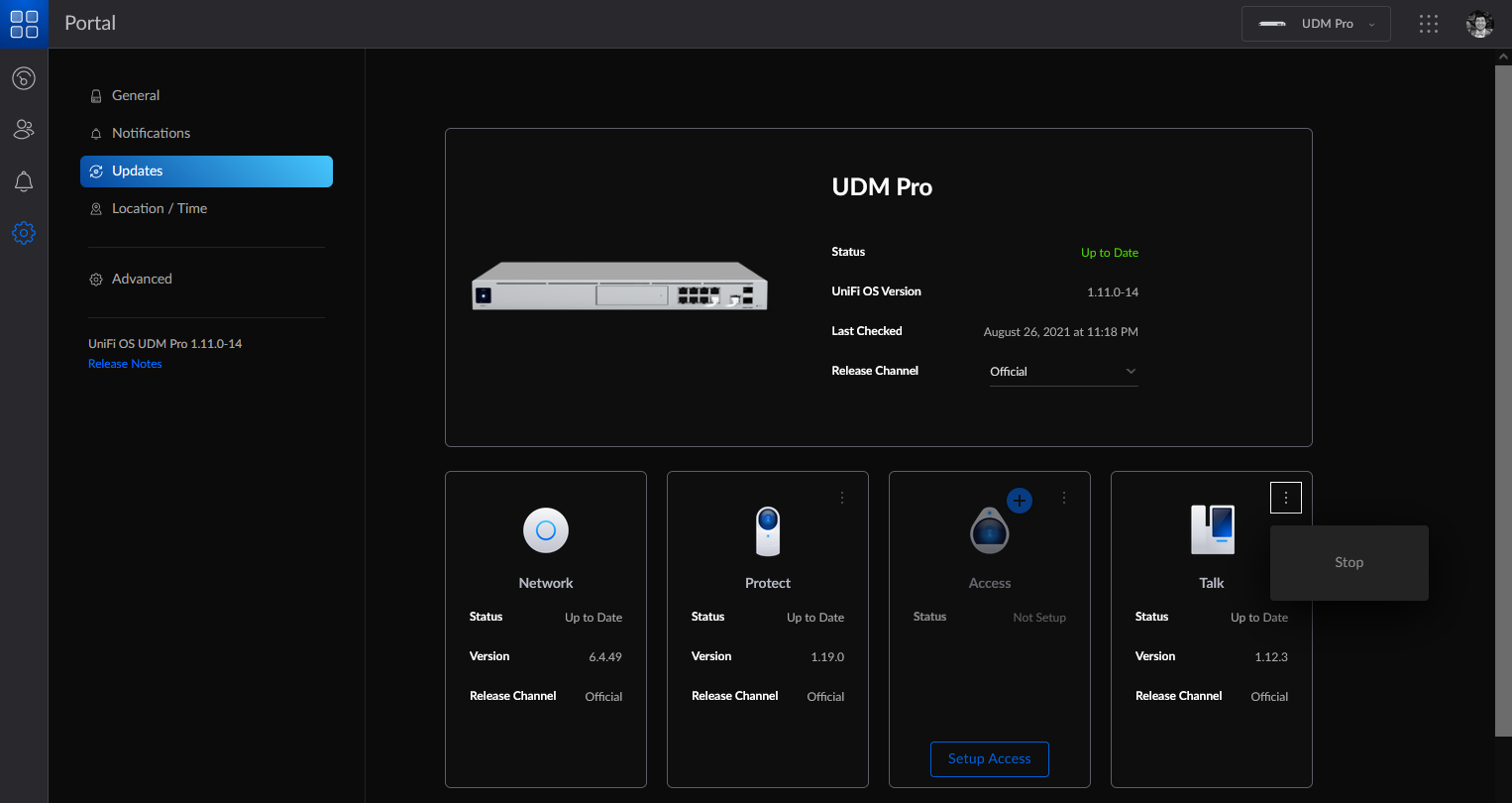
Ensure that the Talk application is running. To check on Talk’s status, open unifi.ui.com, select your UniFi OS Console, go to Settings> Updates, and locate the Talk application tile. If Talk is stopped, click on the three dots menu in the Talk application tile and select Start.
Restart the Talk application. See this section for instructions on how to restart Talk.
Restart your UniFi OS Console by going to its Settings > Advanced and clicking Restart Console under the Console Controls header. If you’re still encountering this issue after the troubleshooting steps above, please contact Ubiquiti Support.
To create new users in the UniFi Talk application:
Open the Users tab and click the Add User button in the top-right corner of the screen.
Type the user’s first name, last name, and extension in the respective text fields. If you do not assign an extension, the UniFi Talk application will do so automatically.
Select the user’s phone number from the drop-down menu and click Save. If no phone number is selected, the user will only be able to make internal calls unless they are added to a group with a number assigned.
Assign phones to users
A user must be assigned to each phone managed by the UniFi Talk application. You can assign a phone to a user on the Devices page or in the user’s profile panel.
To assign a phone to a user on the Devices page:
Click the Devices icon in the left navigation bar.
Hover your cursor over the phone you’d like to assign to the user, then click the Assign link when it appears.
Select the user from the pop-up window’s drop-down field, then click Assign.
To assign a phone to a user via their profile panel:
Click the Users icon in the left navigation bar.
Click the user that you’d like to assign a phone to.
Click the Manage tab, then scroll down and click the Manage drop-down option.
Select the phone that you’d like to assign to the user from the Reassign Device drop-down field.
Click the user that you’d like to assign a number to.
Click the Manage tab, then scroll down and click the Manage drop-down option.
Select the number that you’d like to assign to the user from the Change Number drop-down field.
Click Save at the bottom of the panel.
Note: Users without a number assigned will not be able to make or receive external calls, but will still have an active extension that can make and receive unlimited internal calls.
Add a third-party SIP provider
Session Initiation Protocol (SIP) providers facilitate real-time video and voice communication (e.g., Twilio, Voxbone, 3CX, etc.). If you currently subscribe to a third-party SIP provider, you don’t have to purchase a UniFi Talk subscription to use your existing service in the UniFi Talk application.
To add a third-party SIP provider to your UniFi Talk application:
Create and configure a new trunk in your SIP provider’s settings console:
Create a credential list and assign username and password credentials to the trunk itself.
Add an ACL IP and a new entry for your router’s public IP address (e.g., 1.2.3.4/32).
Add an origination uri in the same format as your router’s public IP address (e.g., sip:1.2.3.4:6767).
Ensure that the Direct Inward Dialing (DID) number(s) you want to use with UniFi Talk are assigned to the newly created trunk.
Add your SIP provider’s information to the UniFi Talk application:
Go to Settings > System Settings.
Click the Add Third-Party SIP Provider button at the bottom of the screen.
Enter your provider’s name.
Enter your SIP provider’s required fields:
Locate your SIP provider’s custom fields by referencing either the Providers ITSPs directory or your provider’s user documentation.
Click the Add Field button in the UniFi Talk Settings menu.
Type or paste the copied field into the Add Fields window and click the + icon. Repeat this process for multiple entries.
Click Done once all fields have been added.
Type the DID number(s) from your SIP provider in the Input Numbers field(s) in either E.164 format (e.g., +10123456789) or the format supported by your provider.
Add your SIP provider’s media and signaling servers:
Click the Add IP Address Range button.
Type the address information in the corresponding fields and click Add.
Enable the Static Signaling Port toggle located in the Network tab of the UniFi Talk Settings menu.
Assign the new DID number(s) and phone(s) to users registered in your UniFi Talk application:
Open the Users page of your UniFi Talk application.
Click the desired user then click the Manage tab at the top of their profile panel.
Select the phone that you’d like to assign the user from the Reassign Device drop-down menu.
Select the DID number that you’d like to assign the user from the Change Number drop-down menu.
Repeat this process as needed for additional users.
Note: If you’re using a third-party SIP provider, said provider will be responsible for maintaining E911 compliance. Please contact your provider for more guidance on how to ensure that all requirements are met.
Add or adjust port forwarding rule(s) for the UniFi OS Console hosting the UniFi Talk application:
Open the UniFi Network Settings menu and click the Firewall & Security tab.
Locate the Port Forwarding section and click the Create New Forwarding Rule button.
Add all required information to apply the port forwarding rule(s) to your UniFi OS Console.
If you have another router upstream from your UniFi OS Console, forward incoming traffic to Port 6767 of your UniFi OS Console.
Set up a Smart Attendant
The Smart Attendant helps you create and execute custom call routing to ensure that all your calls are directed to the right extension or preferred language speaker.
To set up a Smart Attendant:
Open the Smart Attendant tab in the UniFi Talk application. If you already have one or more Smart Attendants, click the Add New button. Otherwise, proceed with setup.
Name your Smart Attendant and click Next.
Select the number(s) you want the Smart Attendant to answer from the drop-down field.
If you select None, your Smart Attendant will not be active until you assign it a number.
You can also select multiple numbers for your Smart Attendant to answer.
From this screen, you can also configure the Ringback and Hold Music that your Smart Attendant will use.
Ringback: The audio that callers hear when dialing a Talk user or group via your Smart Attendant.
Hold Music: The audio that callers hear when a Talk user places them on hold after being dialed via your Smart Attendant.
Select if your Smart Attendant will behave differently based on business hours. When enabled, you can define custom call handling for business hours and non-business hours.
If you select Yes, configure your business hours schedule. You can add multiple business hour segments within a single day.
Select if you wish to have extension dialing enabled. When enabled, callers can dial an extension to connect with a user or group without going through Smart Attendant menus.
If you select Yes, select an extension dialing method:
All Users and Groups: All users and groups in your Talk application can be dialed by their extension.
Custom List: Only the Talk users and groups added to the custom list can be dialed by their extension.
Smart Attendant Ring Menus: Only the Talk users and groups added to the Smart Attendant with a Ring Phone(s) menu can be dialed by their extension.
Configure your Smart Attendant’s greeting message:
Select the voice your Smart Attendant will use for generated audio.
Select the greeting type. You can generate audio from text or use custom audio by recording or uploading a file.
Following the instructions to configure your greeting based on the type selected.
Create your call routing tree:
Enter the prompt message and select the user(s) and/or group(s) that each key press will direct to.
If you don’t need a call routing tree or wish to configure this later, click No then Finish.
To add a new menu or user:
Hover your cursor over the menu that you’d like to add a new block to and click the + icon when it appears.
Choose between the two different types of blocks:
Keypress Prompt (e.g., Press 1 for Sales)
Ring Phone(s) (Dial a specific user or group)
Play Audio (Play an audio message)
Voicemail (Leave voicemail for a specific user)
Keypress to Return (Return to the previous menu)
Schedule (Configure call handling based on a schedule)
To delete a menu or user, hover your cursor over it and click the X icon when it appears.
Manage voicemails and call recordings
The UniFi Talk application collects voicemail by default. To listen to voicemails, click the Voicemail button on your Talk phone.
To automate call recordings:
Enable the Automatic Call Recording toggle from Settings > Call Settings.
Review the disclaimer text in the pop-up advisory window carefully, and click I Understand if you consent.
To disable voicemail:
Open the Settings menu and click the Call Settings tab.
Open the Voicemail drop-down.
Disable the voicemail toggle.
View call logs
To view your call logs:
Open the Call Log tab to view a listing of every call made with a device managed by the UniFi Talk application.
View the details of a specific call:
Click the desired call’s entry or hover your cursor over its listing and click the View link when it appears.
Review basic call information (e.g., caller, recipient, call experience score, length, date, and time) from the General section of the call log’s pop-up panel.
Click the Recording tab at the top of the call log’s panel to listen to its recording.
For voicemail messages, click the Voicemail tab at the top of the call log’s panel to listen to its recording.
To delete a call log, hover your cursor over the log’s entry and click Delete, then click the Delete button in the confirmation pop-up window.
Set up groups
The UniFi Talk application allows you to create groups that allow multiple phones to share the same number and ring. Groups can utilize all UniFi Talk application features, including the Smart Attendant.
To create a new group:
Click the Groups icon in the left navigation bar and click the Create New Group link in the top-right corner of the following page.
Enter a group name, assign a number to the group (optional), and add an internal extension (optional).
Select either Simultaneous or Sequential call handling.
Simultaneous: When the group is called, all phones assigned to group members will ring. The first phone to answer will receive the call and the other phones will stop ringing.
Sequential: When the group is called, phones assigned to group members will ring in the order you define.
Manage the group’s members. You can add Talk users and global contacts to a group.
Configure the Ringback for the group. This is the audio that callers hear when calling the group.
Click Create.
Note: Groups without a number assigned will not be able to make or receive external calls, but will still have an active extension that can make and receive unlimited internal calls.
To assign a specific outgoing number to a user who is a member of several groups:
Open the Users page, select the user, and click the Manage tab.
Select the desired outgoing number from the drop-down field.
Troubleshooting
I can’t receive incoming calls
We recommend enabling the static signaling port feature if your UniFi Talk deployment can’t receive incoming calls. The instructions below describe how to implement this fix.
In the Talk application, enable the toggle for static signaling port within Settings > System Settings > Create Static Signaling Port.
Create a port forwarding rule that forwards port 6767 to your UniFi OS Console running the Talk application. If your routing tasks are being handled by UniFi, go to the Network application to create this rule within Settings > Advanced Features > Advanced Gateway Settings > Port Forwarding. Need help creating this port forwarding rule?
Try making a call to one of your UniFi Talk phones from an external number to test if incoming calling is working.
If the steps above did not work, try creating a firewall rule that allows Internet traffic destined for port 6767 of your UniFi OS Console running the Talk application. If your firewall rules are managed by UniFi, go to the Network application to create this rule within Settings > Traffic & Security > Global Threat Management > Firewall.Need help creating this rule?
I can’t make outgoing calls
For outgoing call failures, we recommend disabling the SIP ALG setting found in the router upstream from the UniFi OS Console running the Talk application (e.g., the router modem installed by your ISP). The SIP ALG setting is sometimes enabled by default on these devices and interferes with telephony.
I could previously make and/or receive calls, and now I can’t
In some cases, events like a network outage can result in degraded Talk application performance. This can be resolved by restarting the Talk application.
To restart the Talk application:
From unifi.ui.com, select your UniFi OS Console, go to Settings> Updates, and locate the Talk application tile.
Click on the three dots menu in the Talk application tile and select Stop.
After the Talk application has stopped, click on the Start Talk button.
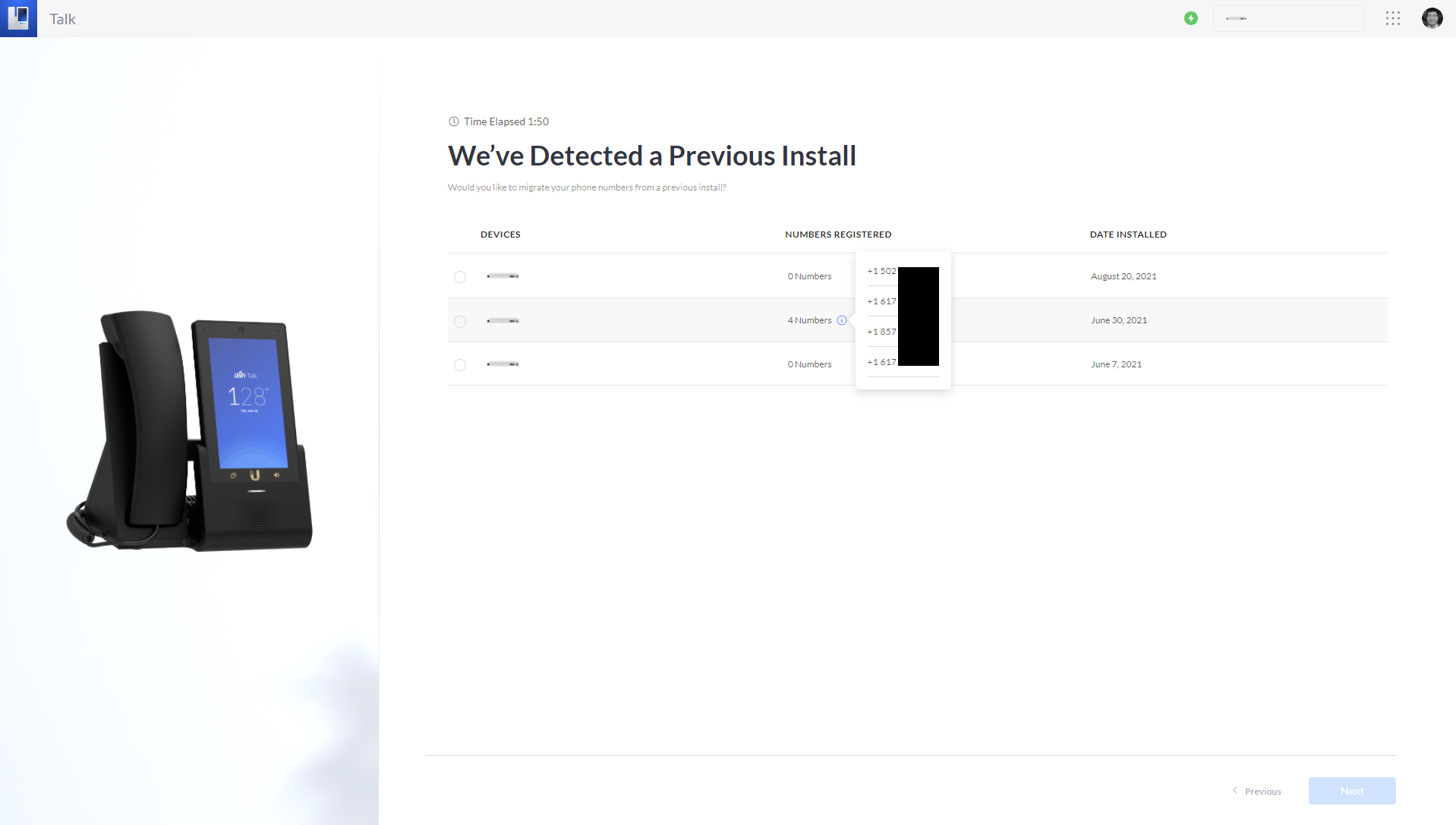
If you need to factory reset, replace, or migrate to a new UniFi OS Console, or reset the Talk application, you can recover your Talk subscriptions and phone numbers during the UniFi Talk setup process. This option is available when you’re logged in using the same Ubiquiti account that manages your Talk subscriptions.
To recover or migrate your Talk subscriptions:
Log in to your Ubiquiti account at unifi.ui.com and select the UniFi OS Console you’d like to recover or migrate your Talk subscriptions to.
Launch the UniFi Talk Setup Wizard.
If you have multiple UniFi Talk deployments associated with your Ubiquiti account, you’ll see a list of previous deployments to select from. Hover over the information tooltip to view the phone numbers associated with each deployment.
Select the deployment with the phone numbers that you want to recover or migrate.
Click the Next button to continue setup.
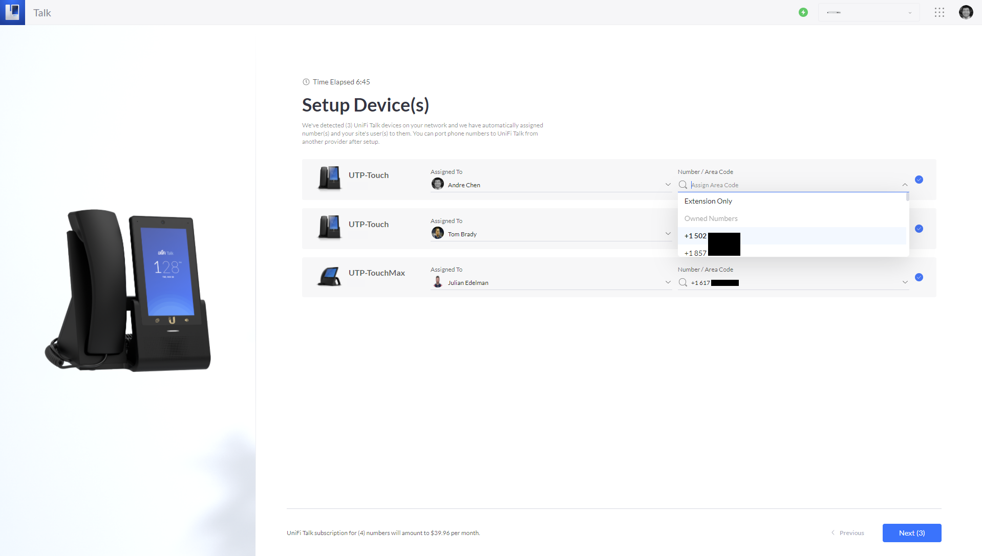
On the Setup Device(s) page, you’ll now have the option to assign your recovered or migrated phone numbers to users and devices. These are available for selection from the Number / Area Code dropdown menu. Make your selections and click Next.
Complete the UniFi Talk setup process to finish recovering or migrating your Talk subscriptions and phone numbers.
Notes: A Talk subscription can only be active on a single UniFi OS Console. If you use this option during the UniFi Talk setup process while a subscription is still active on another UniFi OS Console, your subscription(s) will be transferred and will no longer be accessible from that device.
You can configure UniFi Protect location-based activity notifications so you are only notified when the user(s) are off-site. This article outlines the steps needed to set this up for your account.
In the UniFi OS settings, go to Console Settings > Time Zone / Location>Edit Location on Map.
Search for the Address or drag your UOS Console to the correct location.
Adjust the Geofencing Radius slider to define your console’s on-site radius (i.e, “geofence”).
Click Apply Changes when you’ve set the desired geofence.
If you experience unexpected status changes while on site, increase the geofence’s radius.
Configure your primary mobile device
Your primary mobile device will be the one used to determine whether you are on or off-site (i.e., within the geofence).
To configure your primary mobile device:
Make sure cellular data is enabled on your mobile device.
Make sure that the UniFi Protect mobile app has proper location permissions:
For iOS devices, set the Protect mobile app’s Location Setting permission to Always. Precise Location should also be enabled.
For Android devices, make sure that Protect mobile app’s location access is set to Allow all the time.
Open the Protect mobile app, tap the Settings icon on the bottom-left corner of the screen followed by Primary Device; then, select the desired mobile device from the list.
To activate your UniFi OS Console’s geofence, use the Protect mobile app to go to Settings > UniFi OS Console > Network and enable the Geofencing toggle.
Configure location-based activity notifications
After you’ve configured the locations of your UniFi OS Console and primary mobile device, you can create activity notifications using your UniFi Protect web application or mobile app.
To create activity notifications using the UniFi Protect mobile app:
Go to Settings > Notificationsto create a new activity notification or edit an existing one.
Select from Off, Default, or Custom.
If you choose Custom, click the Activity tab to customize the notification for each camera.
To create or edit activity notifications using the Protect web application:
Log in and go to Settings > Notifications > Activity.
Adjust When to Send> Location Based to receive notifications when you are off site (When I’m Away) or when all users are off site (When Everyone is Away).
Go back and customize the notifications for your cameras.
Troubleshooting inaccurate location tracking
The Protect mobile app uses GPS and communication with the UniFi OS Console to provide an accurate location.
If you are experiencing location inaccuracies, follow the device-specific steps below to improve the mobile app’s location tracking:
For iOS / iPadOS devices:
Disable Low Power mode, as it may prevent the app from sending location status updates.
Enable Background App Refresh and Cellular Data for the UniFi Protect mobile app.
Disable VPN or Mobile Hotspot if they interfere with location accuracy.
For Android devices:
Select High Accuracy mode for mobile phone location tracking, if available.
Disable data saving settings.
Disable battery optimization for the UniFi Protect mobile app by tapping Settings > Battery > Battery Optimization > Don’t Optimize.
Disable power saving mode to ensure it isn’t auto-enabled once your phone battery is low.
If your mobile has a Deep Sleep feature, disable it for the UniFi Protect mobile app to make sure you don’t receive location status updates after opening it.
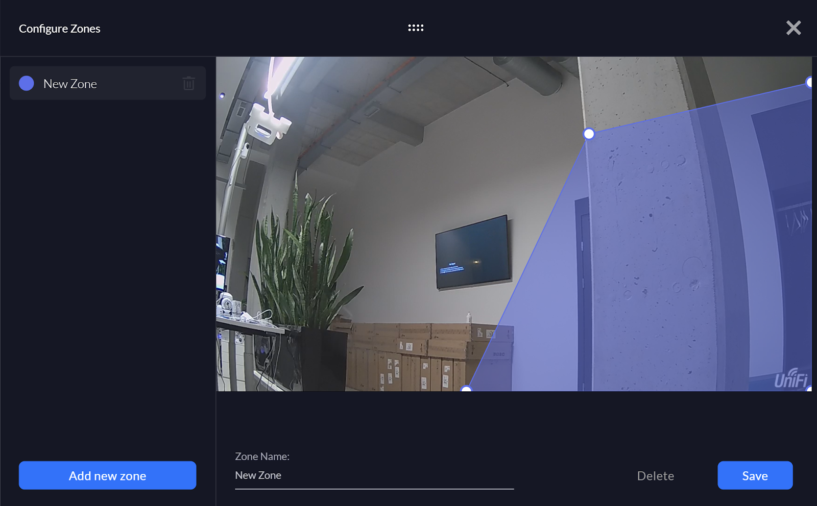
There are three different types of camera zone settings you can use:
MotionZones, which tell the camera to recognize motion in specific zones and trigger certain actions, e.g. record footage and create Motion Detections for you to review later
PrivacyZones, which let you block out certain areas on the video recordings
SmartDetection (AI and G4 camera series), which let you create Events for certain types of motion, e.g. when the camera detects a person
Set up motion zones
Motion zones are specific zones where the camera will detect and record motion.
To trigger and record motion events and also trigger motion alerts, the camera recording settings must be set to Always or Detections.
Go to the Devices section and select the desired camera.
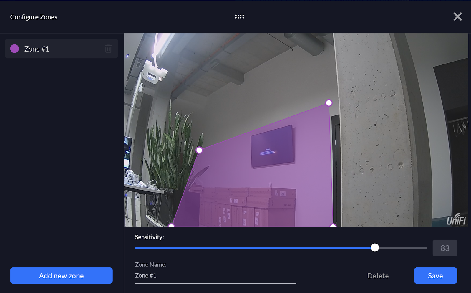
On the right side panel, select Zones > Expand Motion Zones > Add Motion Zone.
Create the Motion Zone by clicking on the four corners of its perimeter. You can further adjust the corners by dragging them with your cursor.
Adjust the zone’s detection sensitivity based on your camera’s surroundings using the slider node below the feed window.”
To set up a motion zone on the mobile app:
Select the desired camera on the home screen.
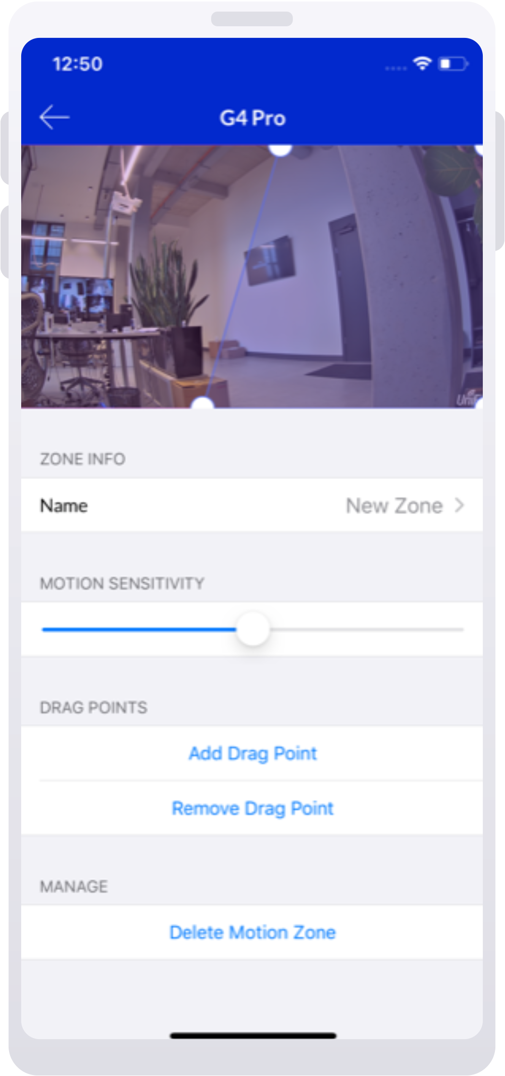
Tap on the Settings icon in the upper-right corner of your screen, then select Motion Zones > Add Motion Zone.
Create the Motion Zone by clicking on the four corners of its perimeter. You can further adjust the corners by dragging them with your cursor.
Adjust the zone’s detection sensitivity based on your camera’s surroundings using the slider node below the feed window.
Please note that adjusting the recording setting to Never disables motion detection recording and alerts.
When setting up zones, you can adjust the zone sensitivity. Setting a higher value will make your camera more sensitive, making it more likely to detect and log more subtle motions (e.g., small object movements).
If you’re getting an increased amount of motion events due to minor movements such as moving branches, decrease zone sensitivity to prevent excessive minor motion event logging.
Set up Smart Detection zones
Smart Detection Zones create events when specific motions are detected (e.g., a person’s movement).
Currently Smart Detection zones only supports person detection, meaning that you will only be notified when this specific motion event occurs.
The Smart Detection feature is only available for G4 and AI series cameras, except for G4 Instant.
To set up Smart Detection zones:
Go to Devices > Propertiespanel > Recordings and enable Person detection.
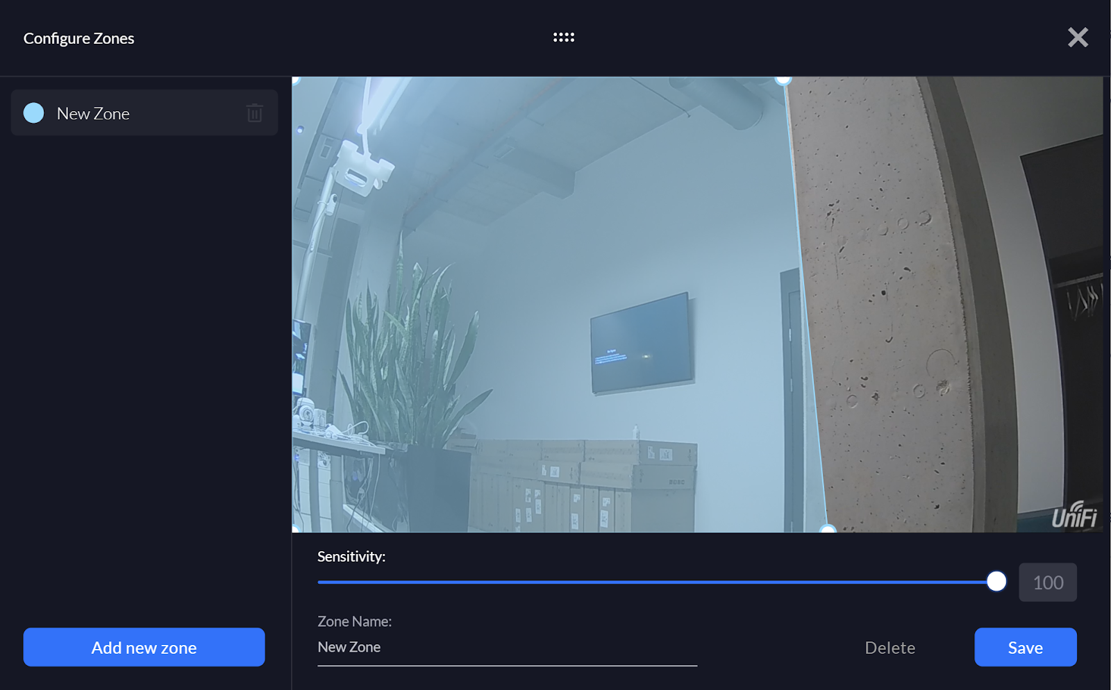
Go to the Zones section, click Add new zone, and name it.
Create the Smart Detection Zone by clicking on the four corners of its perimeter. You can further adjust the corners by dragging them with your cursor.
Adjust the zone’s detection sensitivity based on your camera’s surroundings using the slider node below the feed window.
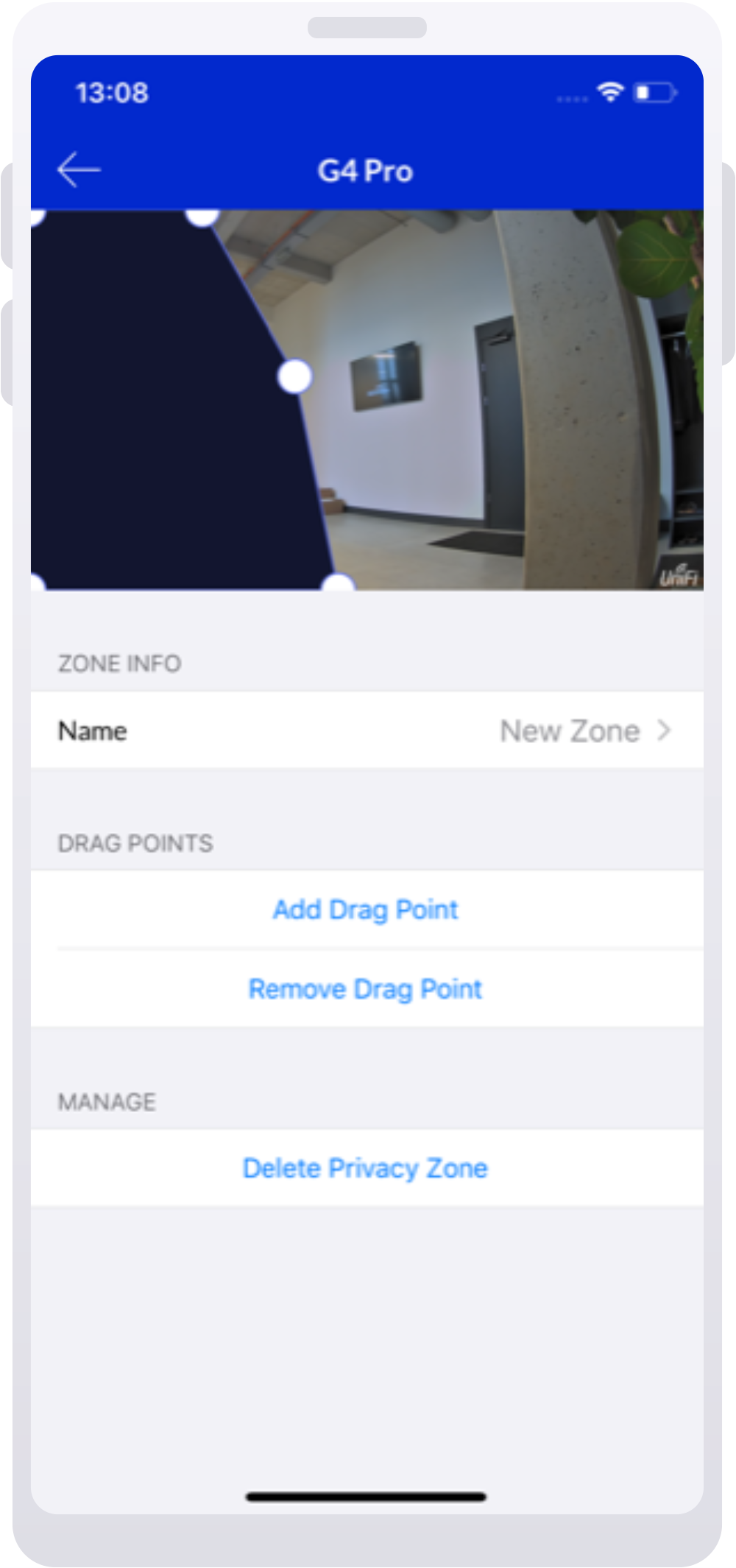
Set up privacy zones
You can set privacy zones for each of your cameras, which block live playback and recordings of content within the specified area. Instead, you will see a blacked-out image.
To set up a privacy zone on the web application:
Go to the Devices section and select the desired camera.
On the right side panel, select Zones > Expand Privacy Zones > Add Privacy Zone.
Create the Privacy Zone by clicking on the four corners of its perimeter. You can further adjust the corners by dragging them with your cursor.
To set up a privacy zone on the mobile app:
Select the desired camera on the home screen.
Tap on the Settings icon in the upper-right corner of your screen, then select Privacy Zones > Add Privacy Zone.
Create the Privacy Zone by clicking on the four corners of its perimeter. You can further adjust the corners by dragging them with your cursor.
The UniFi Protect mobile and web applications allow you to view live and recorded footage as well as adjust the image and video playback quality.
Live View
By default, the video bitrate of your cameras is automatically reduced during prolonged periods of low motion frequency in order to reduce storage utilization. You may choose a specific resolution by changing the Viewer Quality to Low or High on the Protect web application by hovering over the Live View, or on the mobile app within the Live View’s specific settings.
Note: If your bandwidth is limited, you may experience unstable playback while viewing a high quality live feed.
Recordings and Detections
Your recording’s duration and quality will depend on the camera’s Recording Mode. The When to Record setting can be set to Always, Never or Detections. Image quality and frame rate can be adjusted using the Recording Quality setting.
Note that:
A higher frame rate will give you smoother video playback while a lower frame rate will ensure better picture quality.
Recording with higher image quality will require more storage space than lower quality ones.
You can download the Detection clips from the mobile app by tapping the Share icon > Export clip, or from the web application by selecting the detection and clicking the Download icon.
Adjust the Camera Picture Settings
Most image quality issues can be resolved by adjusting the camera picture settings, which are specific to each camera and found within Devices > select a camera > Settings.
The camera’s image is dull, dark, or distorted
To correct imagery that appears dark, dull, or distorted:
Open the camera’s settings and select Adjust Camera Picture.
Adjust the Brightness, Contrast, and Hue settings for the camera.
Note: There is no definite way of setting this for all cameras in any environment. Try adjusting these settings to achieve the desired image quality outcome.
The camera recording quality is low
To improve a camera’s recording quality, open its Recording Mode settings and increase the Frame Rate and Image Quality settings as described above.
The camera’s image is harshly lit
Harsh lighting creates a strong contrast that can make it difficult to see smaller, finer details in your live feeds and recordings. To resolve this, try enabling the HDR feature (or WDR depending on the camera model) in the Camera Picture settings.
The camera is out of focus (G3 Pro, G4 Pro, G4 PTZ cameras only)
If your G3 Pro, G4 Pro, or G4 PTZ cameras appear to be out of focus:
Make sure there are no objects between the camera and its focal point that may affect its ability to auto-focus.
Try manually setting the focal point with the Focus Camera Picture setting.
The camera isn’t switching to Night (IR) Mode
If your cameras are not switching to Night (IR) mode, or are rapidly alternating between Night and Day Mode, verify that:
Each camera’s infrared setting is set to Auto.
There are no external light sources, such as ambient lights in front of a camera, affecting integrated light sensors.
There are no obstructions near the front of the camera. Obstructions can cause the camera’s infrared light to reflect back at its sensor, causing it to switch back and forth between Night and Day Modes.
Night (IR) Mode imagery is blurry
If your Night (IR) Mode imagery is blurry:
Carefully clean your camera’s lens or dome using a soft cloth and isopropyl alcohol. The alcohol’s concentration should not exceed 70%; otherwise, you risk damaging its surface. Be sure to remove all residue to prevent unwanted reflections.
Ensure that no obstructions near the camera’s lens are causing IR reflections.
(For Dome cameras) Make sure that the dome cover is tightly secured to the lens housing. The rubber gasket should be firmly fastened to the dome’s surface and the dome should be in the locked position.
The G4 Dome camera is equipped with infrared LEDs to give it night vision. However, some factors may cause these LEDs to produce glares on the camera’s feed. The most common causes of glaring and poor resolution are:
Per its installation guide, the G4 Dome should be installed at least 60 centimeters (cm), or 24 inches, away from neighboring walls and the ceiling. If nearby objects or fixtures, such as a wall corner or overhang, are closer than that, they may reflect infrared light into the camera and create a glare.
Ceiling-mounting near a wall corner
Below, you can see how mounting the G4 Dome to the ceiling with objects in the foreground can result in poor image quality.
Ceiling-mounting near overhangs
The camera below is too close to the pillar so it appears in the camera’s field of view (FoV).
Wall-mounting too close to the ceiling
The camera below doesn’t have at least 60 cm of separation from the ceiling and its image quality is diminished as a result.
Residue on the bubble cover or lens
While installing the G4 Dome, its lens and bubble cover may collect dust, oil stains, and fingerprints. This can also occur if you wipe the lens or bubble cover incorrectly.
If there is residue on the G4 Dome’s lens or bubble cover, clean them with either lens wipes, a lens cloth with a lens cleaning solution, or a soft cleaning cloth and rubbing alcohol. Continue to do this periodically to prevent distorted image quality due to dirty lens and cover surfaces.
Oil stains or fingerprints on the bubble cover or lens
When oil stains stick to the bubble cover or lens, the infrared lights become diffused by the foggy surface.
The image below shows the camera’s bubble cover marked with fingerprints.
The image below shows a lens with oil stains.
Below, you can see how image quality with a clean bubble cover is markedly better than that of an oil-stained equivalent.
Moisture droplets on the bubble cover
When moisture droplets stick to the bubble cover, the camera’s infrared lights become scattered by the trapped moisture, like in the example directly below.
To avoid reduced image quality due to moisture droplets, wipe the bubble cover’s exterior with a lens cloth.
Bubble cover not properly locked in place
The G4 Dome’s removable bubble cover has a locking mechanism to ensure an airtight seal. When the bubble cover is not attached properly, the camera’s infrared lights can be reflected back into its lens.
To mount the bubble cover correctly:
Align the small indentations on the cover and camera.
Rotate the cover clockwise to securely fasten its rubber lining. The sealing strips should not be visible.
The example images below show the G4 Dome when its bubble cover is properly attached (left), and when it’s not (right).
Here, you can see the G4 Dome’s image quality when its bubble cover is properly attached.
Here, you can see how its image quality is greatly reduced by an incorrectly attached cover.
The rubber seal surrounding the lens is damaged
When the rubber seal surrounding the lens is damaged, infrared light can leak in and distort the camera feed.
The images below show a normal seal (left) and a damaged one (right).