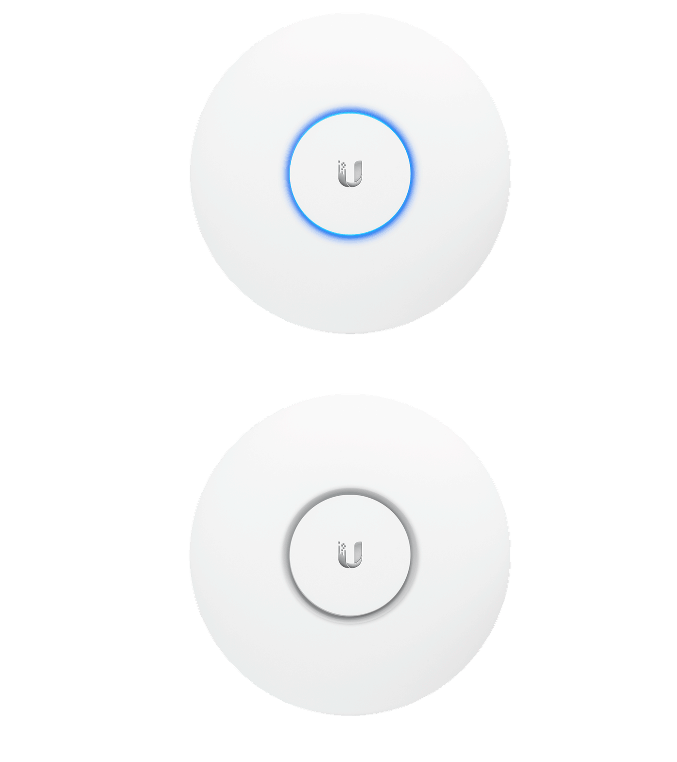
Ubiquiti UniFi – Explaining the system.properties File

This article describes what the system.properties file is used for and how to edit it.NOTES & REQUIREMENTS:This article includes some advanced configurations that should only be performed by advanced users. Advanced configurations are not supported by our Support team. The Community is the best place to find experts to guide you with advanced configurations.

Table of Contents

  1. Introduction
  2. Manually Specify the IP Interface for UniFi Network Application Communication
  3. Advanced Database Configuration
  4. SMTP Related Settings
  5. User Tips & Notes

Introduction

The system.properties file, found within <unifi.base> in the data folder, is the file inside the UniFi server installation directory, which defines system-wide parameters for the UniFi Network application. Here are just a few notable examples of supported configuration changes for UniFi Network application made in the system.properties file:

  • Manual override of the Application IP Interface (the address to which Devices send inform packets).
  • Advanced Database adjustments.
  • Port Assignments, for purposes of the UniFi Network application communicating with Managed Devices, redirecting Guest Portal traffic, etc.

WARNING:Before editing the system.properties file, remember to create a backup of your system and download it to a safe place. It is also necessary to stop the application before performing any change in the file to avoid errors after changes are made.

The system.properties file can be edited directly via any text editor. Keep in mind that lines preceded by hash-tags (#) exist as comments and are non-operational. Make edits at the bottom of the file. After changing this file, you’ll need to manually trigger provisioning on each site in order to make these effective.NOTE:The system.properties file is created when UniFi Network runs successfully. If you cannot find the file within the <unifi_base>, create it by running the UniFi Network application .

Manually Specify the IP Interface for UniFi Network Application Communication

If a UniFi OS Console (or device hosting the application) has multiple IP interfaces, the following configuration can manually set the exact IP interface that adopted APs should communicate to the Network application:

  • system_ip=a.b.c.d           # the IP devices should be talking to for inform

Advanced Database Configuration

Below are advanced database configurations that most users will never need. Note: We do not perform tests on these configurations, they are enabled for the convenience of database experts. One possible usage scenario is where few people run their application on a NAS, which has a smaller footprint than a normal server, hence there’s a need to reduce the required resources.

  • unifi.db.nojournal=false    # disable mongodb journaling
  • unifi.db.extraargs            # extra mongod args

The configuration below is used to facilitate UniFi Network application installation. Again, most users will never need to set this. When the is_default is set to true, the application will start with factory default configuration. For normal, everyday users, an uninstallation and then fresh re-installation is recommended over this.

  • is_default=true

From the UniFi Network application you can configure the autobackup frequency, amount of backups to store, time of backup, etc. At the time of writing this, you cannot change the storage location via the application. We do have a variable in the system.properties if you wish to change the storage location. Currently, the default points to:

1. For Cloud Key: /data/autobackup (where SD card is mounted as /data by default)
2. For software installs: {data.dir}/backup/autobackup

  • autobackup.dir=/some/path

The UAP-AC-EDU is recommended to be managed from a local application. The current communication from the EDU mobile app relays from app to Network application to EDU. If the mobile device is remote to the EDU, then you just need to open the appropriate ports. If the UniFi Network application is remote to the EDUs, then you need to add the following line to system.properties.

  • stream.playback.url.type=inform

(5.5.15+/5.6.7+) We’ve added HSTS support to the application. Do note that it is default disabled. This should only be enabled if you know what you’re doing with it. This will only ever be a system.properties value so it can be easily disabled in case of issues. If you run into issues, you likely will need to clear your browser’s cache after disabling this and restarting the service. To enable HSTS support add the following:

  • unifi.https.hsts=true
  • unifi.https.hsts.max_age=31536000
  • unifi.https.hsts.preload=false
  • unifi.https.hsts.subdomain=false 

NOTE: Currently no characters after the custom line(s) are allowed. This includes spaces, pound/sharp signs/comments, etc.

SMTP Related Settings

By default, SMTPS validates certificates and will reject self-signed or untrusted certificates. If your mail server uses an untrusted certificate, you must disable certificate verification with the following: smtp.checkserveridentity=false

Starting with UniFi Network version 6.1, STARTTLS is opportunistically enabled by default; e.g. will be used if the server announces support for it, and will require a trusted certificate. If using a self-signed or untrusted certificate, you must disable STARTTLS by setting the following: smtp.starttls_enabled=false

This only controls whether STARTTLS will be used if the server supports it. To force its use, see: starttls_required

With UniFi Network version 6.1 and newer, STARTTLS is opportunistically enabled by default, but only required if using port 587. This behavior can be overridden by setting smtp.starttls_required=true to force the use of STARTTLS on ports other than 587, or to make STARTTLS optional on port 587, set it to false.

If smtp.starttls_enabled=false is set, the starttls_required value has no impact.

User Tips & Notes

  • If receiving error, it’s possible there are hash tags (#) present in front of commands. Hash tags indicate comments, and will make commands not work until hash tag is removed.
  • If you want to reduce the logging frequency on your RPi UniFi Network application, see this Community threadATTENTION:Without logs, it is impossible to receive appropriate support. Use this tip under your own discretion. See how to extract logs in our UniFi – How to View Log Files article.
  • If you cannot find the system.properties file, it might not have been created yet. This file is created once the UniFi app runs successfully. If you need to change port numbers because of a port clash, it doesn’t count as a successful launch and does not create the file, so you can’t alter the port numbers to avoid the clash.

    Source :
    https://help.ui.com/hc/en-us/articles/205202580-UniFi-Explaining-the-system-properties-File

Ubiquiti UniFi – Ports Used

This article shows what UDP and TCP ports are used by the UniFi Network application by default. The information applies to both Network applications hosted on UniFi OS Consoles, such as UniFi Cloud Key (UCK-G2UCK-G2-PLUS, and UC-CK) or UniFi Dream Machine (UDM or UDM-Pro), as well as self-hosted Network applications. 

Note: Make sure to always update your Network application to the latest version.

Local Ingress Ports

ProtocolPort numberUsage
UDP3478Port used for STUN.
UDP5514Port used for remote syslog capture.
TCP8080Port used for device and application communication.
TCP443Port used for application GUI/API as seen in a web browser.Applications hosted on a UniFi OS Console
TCP8443Port used for application GUI/API as seen in a web browser.Applications hosted on Windows/macOS/Linux
TCP8880Port used for HTTP portal redirection.
TCP8843Port used for HTTPS portal redirection.
TCP6789Port used for UniFi mobile speed test.
TCP27117Port used for local-bound database communication.
UDP5656-5699Ports used by AP-EDU broadcasting.
UDP10001Port used for device discovery.
UDP1900Port used for “Make application discoverable on L2 network” in the UniFi Network settings.

Note: Although TCP 22 is not one of the ports UniFi Network operates on by default, it is worth mentioning in this article since it is the port used when UniFi devices or the Network application is accessed via SSH.

Ingress Ports required for L3 management over the internet

Note: These ports need to be open at the gateway/firewall as well as on the UniFi Network application host. This would be achieved by creating port forwards on the gateway/firewall where the application is hosted.

ProtocolPort numberUsage
UDP3478Port used for STUN.
TCP8080Port used for device and application communication.
TCP443Port used for application GUI/API as seen in a web browser.Applications hosted on a UniFi OS Console
TCP8443Port used for application GUI/API as seen in a web browser.Applications hosted on Windows/macOS/Linux
TCP8843Port used for HTTPS portal redirection.
TCP6789Port used for UniFi mobile speed test.

Egress Ports required for UniFi Remote Access

Note: In most cases, these ports will be open and unrestricted by default.

ProtocolPort numberUsage
UDP3478Port used for STUN.
TCP/UDP443Port used for Remote Access service.
TCP8883Port used for Remote Access service.

Changing Default Ports

Changing default port assignments can only be done on self-hosted Network applications (Windows/macOS/Linux). This can be accomplished as follows:

1. Close any instances of the UniFi Network application.

2. Modify the system.properties file, which can be found in the directory <unifi_base>/data/system.properties.

  • For example, if port 8081 was in use and port 8089 was open, you could change it by modifying unifi.shutdown.port=8081 to unifi.shutdown.port=8089

3. Restart the UniFi Network application.

Note: Make sure there are no leading or trailing spaces, comments, or other characters like hash tags (#) on any custom lines. Otherwise, UniFi Network will ignore the customizations.

Source :
https://help.ui.com/hc/en-us/articles/218506997-UniFi-Ports-Used

Ubiquiti UniFi – UAP Status Meaning Definitions

This article describes the different statuses a UniFi Access Point might be ascribed by the UniFi Network application within the UniFi Devices section.

device.status.png
Device StatusDescription
ConnectedThe UAP is physically wired to the network by ethernet cable. The UAP is in a connected state, able to service WLAN stations. Currently, no updates/changes to configuration are being run on the UAP.
Connected (Wireless)The UAP is wirelessly uplinked to a physically wired AP.
Connected (100 FDX)The UAP is physically wired to the network at 100 Mbps in full-duplex mode. This will appear when a UAP is connected but not at the ideal connection rate. FDX stands for Full Duplex. It may appear as 10/100/1000, HDX or FDX.
Connected (Disabled)The UAP has been disabled in the UniFi Network application. Properties > Manage Device > Disable this Device. It will be excluded from the dashboard status, and its LED and WLAN will be turned off.
Connected (Limited)This will appear when a UAP is connected and can reach the UniFi Network application, but is unable to reach either the gateway or the custom IP defined for the uplink connectivity monitor. In this state downlink UAPs (wireless UAPs) will become Isolated.
ProvisioningThe UAP is in a connected state, however it is applying updates/changes to the configuration, and will shortly reboot (temporarily disconnecting WLAN stations), and return back online.
RestartingAfter clicking on the Restart button in the Actions column, the device will restart.
AdoptingDevice is adopting normally.
Pending AdoptionThe UAP has been detected by the UniFi Network application, but is not adopted yet. Click on the Adopt button to do so.
Pending Adoption (Update Required)Devices with firmware that are too old for UniFi Network application will see this when attempting to adopt. Clicking Update will upgrade the Device to the latest stable firmware release and adopt the Device to the application.
Heartbeat Missed  The UniFi Network application did not receive a reply at the dynamically scheduled interval. This will appear before “Disconnected,” usually about 30-45 seconds after missing the interval. This is usually seen when configuring a wireless uplink, if state does not change to connected after a while something went wrong. See this article for wireless uplink instructions.
Disconnected The adopted UAP is now in a disconnected state, meaning the UniFi Network application does not have connectivity to the access point (check cables, network settings, and changes to topology).
IsolatedThe adopted UAP is unable to reach the gateway and is awaiting a nearby, wired UAP, which is already managed by the UniFi Network application in order to establish “wireless uplink.” See this article for wireless uplink instructions.
Managed by OtherA UAP is located on the same network as the UniFi Network application, but is already bound to another UniFi Network application. Providing the username/password to the UAP will unbind the UAP from the existing Network application and begin adoption in current application. See this article: UniFi – Advanced Adoption of a “Managed By Other” Device.
UpgradingThe UAP is upgrading and should not be disconnected. This should be accompanied by the AP’s LED flashing. (See what the different LED combinations mean in this article).
RF ScanningAppears when an RF Scan is taking place.

Source :
https://help.ui.com/hc/en-us/articles/205231710-UniFi-UAP-Status-Meaning-Definitions

Ubiquiti UniFi – How to View Log Files

 directory for Linux is mentioned below as it is the consistent folder location on the officially supported distros. It is the same whether you install the UniFi Network application on your own installation of Debian or Ubuntu, or a UniFi Cloud Key. Depending on the platform being used, and how it is configured, there will be other locations, but no matter what, on the supported distros, /usr/lib/unifi/logs will always contain the files.

There are three locations where you can view log files related to UniFi devices and the Network application: /var/log/messages, server.log, and mongod.log. See below what you will find in each.

1. UniFi Dream Machines

/var/log/messages

2. UniFi AP: contains info local to UniFi Access Points, like 802.11 info

/var/log/messages

3. UniFi Switch: contains info local to the switch, like port link state changes, spanning tree events, etc.

/var/log/messages

4. UniFi Security Gateway: contains USG’s general logging.

/var/log/messages

5. UniFi Network application:

  • Contains information about the Network application, communication with UAPs, etc:
server.log
  • Contains information about UniFi software local to Network application installed on a PC.
mongod.log

How to View Log Files: UniFi APs and Switches

To view log files under UAP and USW:

1. Connect to UAP or USW via SSH.
2. Type:

cat /var/log/messages

3. View output.

To view the live logs, with output updating in your SSH session as new logs are appended, run the following instead of the above cat command.

tail -f /var/log/messages

How to View Log Files: UniFi Security Gateways

To view log files under a USG:

1. Connect to the USG via SSH.
2. In the EdgeOS CLI, the log can be viewed by running the following commands:

General Logging

show log

IPsec VPN Logging

show vpn log 

FreeRADIUS Logging 

sudo cat /var/log/freeradius/radius.log

DNSmasq Logging

sudo cat /var/log/dnsmasq.log

IPS/IDS Engine Logging

sudo cat /var/log/suricata/suricata.log

3. View live logging.

To view the live logs, with output updating in your SSH session as new logs are appended, run the following instead of the cat command above.

tail -f /var/log/messages

User Tip:If a user would like to only get the last number of lines the tail utility can be used. The command below will output the last 10 lines of the radius.log file. 

sudo tail -n 10 /var/log/freeradius/radius.log

NOTE:Firewall logs aren’t in the UI yet. Please see this Community post for more details.  

How to Download Encrypted Log Files from the Network Application

The Network application also allows users to download log files to share with Ubiquiti support, but these logs are encrypted (for security reasons), so as the user, you wouldn’t be able to view the logs. For viewing, we continue to suggest all the options described above. It is important to note that this support file does not include device logs.

In the Network application, go to Settings System Settings > Maintenance > Support information, and click Download Logs.

For Network applications not hosted on UniFi OS Consoles, you can find the logs in the following locations:

  • Windows: C:\Users\<username>\Ubiquiti UniFi\logs\
  • macOS: /Users/<username>/Library/Application\ Support/UniFi/logs/
  • UniFi Cloud Key and Debian/Ubuntu Linux*: /usr/lib/unifi/logs/ 

    Source :
    https://help.ui.com/hc/en-us/articles/204959834-UniFi-How-to-View-Log-Files

Ubiquiti UniFi – USW Flex Mini Recovery

Overview

This article describes how to recover a bricked USW-Flex-Mini via recovery mode. The first step in the recovery process is to prepare a web server. See the subsections below on how to do that on each of the different operating systems: Windows, macOS and Ubuntu/Debian and then continue to the recovery instructions once that is done.

Table of Contents

  1. How to Prepare a Web Server
    1. How to Prepare a Web Server on Windows
    2. How to Prepare a Web Server on macOS
    3. How to Prepare a Web Server on Ubuntu/Linux
  2. How to Recover a USW Flex Mini
  3. Related Articles

How to Prepare a Web Server

The first step in the recovery process is to prepare a web server. See the subsections below on how to do that on each of the different operating systems: Windows, macOS and Ubuntu/Debian. 

How to Prepare a Web Server on Windows

1. Download Python for Windows (Executable Installer) here.

2. Open the downloaded file and make sure you select Add Python x.x to PATH during installation.

3. After the Python installation open Command Prompt as Administrator and confirm that Python is installed correctly with the command below:

python -V

4. Create a directory for the web server by running the commands below:

mkdir c:\webserver
cd c:\webserver

5. Start the Python web server on port 80. Note that the version of Python can be found with the command from step 3:

Python 3.x:

python -m http.server 80

Python 2.x:

python -m SimpleHTTPServer 80

How to Prepare a Web Server on macOS

1. Download Python for macOS here.

2. After the Python installation open Terminal and confirm that Python is installed correctly with the command below:

python -V

3. Create a directory for the web server by running the commands below:

cd ~
mkdir webserver
cd webserver

4. Start the Python web server on port 80. Note that the version of Python can be found with the command from step 2:

Python 3.x:

python -m http.server 80

Python 2.x:

python -m SimpleHTTPServer 80

How to Prepare a Web Server on Ubuntu/Debian

1. Install Python on your machine with the commands below:

sudo apt-get update && sudo apt-get install python3

2. After the Python installation open a terminal and confirm that Python is installed correctly with the command below:

python_version=$(dpkg -l | grep "^ii" | awk '/python/{print$2}' | grep "^python[0-9].[0-9]$" | head -n1)
sudo "${python_version}" -V

3. Create a directory for the web server by running the commands below:

cd ~
mkdir webserver
cd webserver

4. Start the Python web server on port 80. Note that the version of Python can be found with the command from step 2:

Python 3.x:

sudo "${python_version}" -m http.server 80

Python 2.x:

sudo "${python_version}" -m SimpleHTTPServer 80

How to Recover a USW Flex Mini

1. Prepare a web server as explained above, and set the server / computer’s IP to a static 192.168.1.99. The way to set a static IP on a computer will vary from platform to platform. Find instructions on how to do that in your product’s documentation (Windows, macOS or Ubuntu/Linux).

2. Download the latest firmware (found in Downloads), rename the binary to fwupdate.bin and place it in the directory that was created earlier (webserver).

3. Power down the switch by unplugging from the power source.

4. Press the switch’s reset button and hold it down as you provide power to the switch. Hold the reset button down for over 10 seconds during boot up. The LED pattern should be: blue-white-off blinking.

5. The USW-Flex-Mini should be updated after a while.

Source :
https://help.ui.com/hc/en-us/articles/360045001914-UniFi-USW-Flex-Mini-Recovery

Ubiquiti UniFi – TFTP Recovery for Bricked Access Points

Overview

Readers will learn how to properly recover a UniFi Access Point (UAP) using the TFTP method.

Table of Contents

  1. Introduction
  2. TFTP for Windows
  3. TFTP for Linux & macOS
  4. Related Articles

Introduction

The method described in this article should help recover a “bricked” UniFi AP. This method will not void the device warranty, whereas opening the chassis for serial TTL will void your warranty. Most soft brick issues will be resolved via this procedure. If your issue continues unresolved, it might indicate a hardware issue that cannot be resolved via software. Feel free to contact support if you believe this to be the case.IMPORTANT:When Recovering UAP Gen1 Devices, The device itself will need approximately 5 minutes to finish recovering after the put command is entered.

TFTP for Windows

1. Prior to beginning the TFTP recovery, download the firmware for the device needed by visiting the UniFi Downloads section. Navigate to the UAP in question using the menu on the left, and find the latest firmware file. Confirm it is a .bin firmware file and not the UniFi Network application software file before downloading.

2. Once the correct firmware has been identified, download it and save it on your computer. 

3. Unplug the ethernet cable from the UniFi AP.

4. Using a paperclip press and hold the UniFi AP’s reset button. Make sure you can feel it being depressed by the paperclip. Do not release the button until step 6.

5. While keeping the reset button pressed in, plug the ethernet cable back into the AP. Keep the reset button depressed until you see the device’s LED flashing in upgrade mode (read about LED patterns in this article). This may take up to 25 seconds. User Tip: The UAP will not respond to ping requests while in TFTP recovery mode, but will respond to ARP requests.

6. You may release the reset button. Now the device is in TFTP transfer mode.

7. Set a static IP on your Computer’s NIC. A static IP of 192.168.1.25, a subnet of 255.255.255.0 and gateway of 192.168.1.20 will work.

8. Plug the UniFi PoE injector’s LAN cable directly to your computer.

9. This example uses the Pumpkin TFTP software, which you can download here (clicking link will download the .exe file immediately) and disable the firewall or allow the Pumpkin connection. Click on “Put File”.

Put_File.PNG

10. In “Local Files” browse for the firmware you downloaded and saved previously (in step 1).

Local_Files.PNG

11. In the “Remote host” field enter the gateway you had predetermined (192.168.1.20), then click OK.

Pumpkin_complete.PNG

12. At this point, the file should begin transferring. The firmware will upgrade now and the device will automatically reboot once it has finished. Do not reboot it yourself.

TFTP for Linux & macOS

1. Prior to beginning the TFTP recovery, download the firmware for the device needed by visiting the UniFi Downloads section. Navigate to the UAP in question using the menu on the left, and find the latest firmware file. Confirm it is a .bin firmware file and not the UniFi Network application software file before downloading.

2. Once the correct firmware has been identified, download it and save it on your computer. You will need to know the exact path to your file, so for this example, we are moving the downloaded firmware file to /Users/username/.

3. Go to System Preferences > Network and set your computer’s network IP address to 192.168.1.25, subnet 255.255.255.0 and gateway 192.168.1.20. User Tip: Take note of what your IP address is before changing it. You will have to revert back to the original IP address on step 12.

4. On macOS Open Applications > Utilities > Terminal and type: 

tftp

On Linux, open the command line application of choice and type the following (substituting the bolded path and firmware name for the name of the file you downloaded in step 2 and the path to where it is saved): 

tftp -l ~/path/firmware_name.bin -p 192.168.1.20 69

5. A tftp> command prompt will appear. You are ready to reset the AP and connect it to your computer, while it’s in “upgrade mode”.

6. Unplug the ethernet cable from the UniFi AP.

7. Using a paperclip press and hold the UniFi AP’s reset button. Make sure you can feel it being depressed by the paperclip. Do not release the button until step 9.

8. While keeping the reset button pressed in, plug the ethernet cable back into the AP. Keep the reset button depressed until you see the device’s LED flashing in upgrade mode (read about LED patterns in this article). This may take up to 25 seconds. User Tip: The UAP will not respond to ping requests while in TFTP recovery mode, but will respond to ARP requests.

9. You may release the reset button. Now the device is in TFTP transfer mode.

10. On the TFTP command line in Terminal, paste these four lines and hit enter: 

connect 192.168.1.20
binary
rexmt 1
timeout 60

Click to copy

11. Type the command put followed by the path to the firmware downloaded in step 2 and hit enter. Following the example mentioned in step 2, something similar to this would be typed into the Terminal window:

put /Users/Alex/BZ.qca956x.v3.9.27.8537.180317.1235.bin

IMPORTANT:Remember you must substitute the bolded path and firmware file name with your own path and file name.

Once it is successful, you will see something like this in the Terminal window (bolded words will be different for each user):

tftp> connect 192.168.1.20 
tftp> binary
tftp> rexmt 1
tftp> timeout 60
tftp> put /path/firmware.bin
Sent x bytes in y seconds

The file should begin transferring at this point. The firmware will upgrade and the device will automatically reboot once it has finished. Do not reboot it yourself.

12. Re-connect the PoE injector’s LAN cable into your router. Restore the network IP back to what it was before.User Tip: If your device is having trouble getting adopted by the UniFi Network application after this process, try forgetting the device by going to the UniFiDevices section, clicking on the UAP in question and then within the properties panel that pops up, go to Config (gear icon) > Manage Device > Forget this device. Click on the “Forget” button and try the process again.

Source :
https://help.ui.com/hc/en-us/articles/204910124-UniFi-TFTP-Recovery-for-Bricked-Access-Points

Ubiquiti Best Practices for Managing AirPlay Chromecast on UniFi Network

This article explains best practices for configuring larger UniFi networks with AirPlay/Chromecast devices. For efficient and reliable channel utilization, networks with more than 100 WiFi clients will need the multicast block option to be enabled on each of their SSIDs. This guide is especially useful for schools, stadiums, public venues, or similar networks.

Note: This guide applies to a network with a UniFi Security GatewayUDM, or UDM-Pro. If your network does not have one of these, the steps may need to be adapted. 

Creating a ChromeCast/AirPlay Network

Once your UniFi Network scales beyond a certain number of WiFi clients, it is important to ensure that every AP’s WiFi channel continues to be used efficiently. The broadcast traffic from more than 100 clients is typically high enough that WiFi performance may start to degrade. We always recommend enabling the multicast block option setting for larger networks.

However, this option causes a problem with users that would like to use their ChromeCast/AirPlay devices on the same WiFi network, because those devices will no longer hear the MDNS broadcasts from other devices on the network. They will no longer be discoverable.

In order to gain the performance benefits of multicast block while still maintaining discoverability to these WiFi clients, please follow these steps:

  1. Go to Settings > WiFi and select on the SSID to check that multicast block is enabled if it has more than 100 clients on it.
  2. Create a separate SSID/VLAN for the ChromeCast/AirPlay clients.
    1. Go to Settings > Networks, and add a New Network.
    2. Go to Settings > WiFi, and add a new WiFi Network, ensuring that the Network from Step “a” is selected, instead of LAN.
    3. Go to Settings > Advanced Features > Advanced Gateway Settings > Multicast DNS and enable Multicast DNS, then click Apply Changes.
  3. Forget the old network on your ChromeCast/AirPlay clients and connect them to the new WiFi Network.
  4. Test Discoverability from the appropriate mobile apps.

    Source :
    https://help.ui.com/hc/en-us/articles/4409866388887-Best-Practices-for-Managing-AirPlay-Chromecast-on-UniFi-Network

Ubiquiti UniFi – LED Color Patterns for UniFi Devices

Learn about the different UniFi device status LED color patterns and how to indentify your device’s state based on the LED status.

Status LED patterns

Blue and White status LEDs apply to all our UniFi access points, routers, switches and the UDM (base model) with the exception of the legacy devices: UAP, UAP-LR, UAP-Outdoor5.

Legacy UAPs have Amber and Green LED on the front of the unit. See this section for legacy AP LED patterns.

The animations are for illustrative purposes – the speed of the flashing or strobing patterns below might differ slightly with that of the device.

While the LED patterns below are shown for Access Points, the rest of the UniFi device LED patterns have the same meaning.

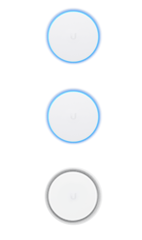
Flashing White / Off every 1/2s

The device is initializing and booting up

UAP-AC-1-Initializing.gif

Steady White

The device is awaiting AdoptionUAP-AC-2-Factory-Defaults.gif

Slow flashing Blue (UDM only)

A client device is connected to the UDM via Bluetooth

UDM-BLE.gif

Steady Blue

The device is adopted and is in normal operating mode

(Access Point is broadcasting SSIDs)

UAP-AC-4-Adopted.gif

Strobing White / Off

If this happens, power cycle the Access Point.

If this doesn’t help, please reach out to our support team.

UAP-AC-9-Error-A12.gif

Quickly flashing White / Blue

The device firmware is currently being upgraded – do not interrupt the process!

(UDM will flash only white during an upgrade)

UAP-AC-7-Firmware-Upgrade.gif

Blue and flashing Off every 5s

Access Point has lost network connectivity and is searching for wireless uplink

UAP-AC-5-Isolated.gif

Rapid flashing Blue / Off

The device “Locate” feature was activated in the UniFi Network application

UAP-AC-6-Locating.gif

Flashing White-Blue-Off

The device is in TFTP mode.

To enable this mode:

  • Hold the reset button before applying power
  • Continue to hold the reset button until this LED sequence appears

If this wasn’t intentional, please check if the device’s reset button isn’t jammed (it should click when pushed).

UAP-AC-TFTP.gif

LED Off

The device is offline.

Verify the Power, POE, and Ethernet cables to troubleshoot.

UAP-AC-8-LED-Off.gif

UniFi Bridge to Bridge (UBB)

Aside from the statuses described above, the UBB has two additional ones:

Red with Circulating Blue LED

The 60 GHz link cannot be established or has dropped due to bad weather. If the UBB fails over to 5 GHz, the LED will remain red. When the 60 GHz link is re-established, the LED will turn blue or the custom color you selected in the UniFi Network application.

Note: If the other bridge device is within range and the UBB LED is red, we recommend adjusting the UBB’s position to enhance the signal strength.

Green

If the Alignment Tool enabled in the UniFi Network application, a green LED means the UBB devices are properly aligned.


Note: If the other bridge device is within range and the UBB LED is green and red, we recommend adjusting the UBB’s position until the LED is green.

Legacy Amber and Green LED patterns

Applies to: UAP, UAP-LR, UAP-Outdoor5.

  • Flashing Amber / Off every 1/2s: The AP is initializing and booting up
  • Steady Amber: The AP is awaiting adoption
  • Steady Green: The AP is adopted and is in normal operating mode (AP is broadcasting SSIDs)
  • Strobing Amber / Off: If this happens, power cycle the AP and reach out to our support team if it doesn’t change the LED pattern
  • Quickly flashing Amber / Green: The AP firmware is currently being upgraded – do not interrupt the process!
  • Green and flashing Off every 5s: AP has lost network connectivity and is searching for wireless uplink
  • Rapid flashing Green / Off: The device “Locate” feature was activated in the UniFi Network application
  • Flashing Amber-Green-Off: The device is in TFTP mode. To enable this mode, hold the reset button before applying the power and continue to hold it until this LED sequence appears. If this wasn’t intentional, please check if the device’s reset button isn’t jammed (it should click when pushed).
  • LED Off: The device is offline. Verify the Power, PoE, and Ethernet cables to troubleshoot.

LED patterns for ports

The ports of UniFi Security Gateways and UniFi Switches have a different type, number, and location.

Please make sure to reference your specific device model’s Quick Start Guide (QSG) for the exact location and description of its ports.

Console Port’s right LED (in the applicable devices):

  • LED Off: Power Off
  • LED Green: Power On 

Speed/Link/Act (right LED ports other than Console):

  • LED Off: No Link
  • LED Amber: Link Established at 10/100 Mbps
  • LED Flashing Amber: Link Activity at 10/100 Mbps
  • LED Green: Link Established at 1000 Mbps
  • LED Flashing Green: Link Activity at 1000 Mbps

PoE (left LED on ports of applicable devices):

  • LED Off: No PoE
  • LED Amber: IEEE 802.3af/802.3at
  • LED Green: 24V Passive

SFP (in the applicable devices):

  • LED Off: No Link
  • LED Green: Link Established at 1 Gbps
  • LED Flashing Green: Link activity at 1 Gbps

See specific port LED information in the Hardware Overview section (between pages 5 and 6) of the Quick Start Guides (QSG). You can find the QSGs in the Documentation section of our UniFi Downloads page, by searching for the device in question in the left hand menu.

LED patterns for PoE Adapters

LED is Off: PoE is Off.

LED is On and steady: PoE is functioning as it should.

LED is blinking: this is not a configured state, this may indicate that the device is not connected properly, or that something is wrong with the cable.

How to disable device LEDs

The device status LEDs can be disabled for all the site, or only for specific UniFi devices.

To enable/disable status LEDs throughout a site, go to to Settings > Site on the UniFi Network application and edit the LED feature in the Services section.

To configure specific devices individually:

  1. Go to the Devices section and click on the device you wish to edit to bring up the Properties panel
  2. Go to Config > General > LED and switch the Site Settings to On or Off.

    Source :
    https://help.ui.com/hc/en-us/articles/204910134-UniFi-LED-Color-Patterns-for-UniFi-Devices

Ubiquiti UniFi – Cloud Key Emergency Recovery UI

This article describes how to access the emergency recovery user interface (UI) and recover a UniFi Cloud Key or a UniFi Cloud Key Gen 2 (UCK-G2-PLUS and UCK-G2 models). From this recovery UI you can reset it to factory defaults, reboot it, power it off and upgrade the firmware.NOTES & REQUIREMENTS:

  • To upgrade the firmware, you will need to download a firmware file (.bin) for the Cloud Key found in our Downloads page. Use the left hand menu to select the correct Cloud Key model and find the newest firmware available.
  • To access this interface you will need to know the IP address of the Cloud Key (visible in the device screen).

Table of Contents

  1. Cloud Key Gen 2 Emergency Recovery
  2. Cloud Key Gen 1 Emergency Recover
  3. Related Articles

Cloud Key Gen 2 Emergency Recover

For second generation Cloud Keys (UCK-G2 and UCK-G2-PLUS) follow these steps to access the Emergency Recovery UI:

  1. Power off the system.
  2. Press and hold the reset button and then power on the Cloud Key by connecting it to the power source.
    • Cloudkey G2:
    • CloudKey G2 Plus
  3. Keep the reset button pressed for about 10 seconds, or until you see the recovery LED pattern in a loop (blue – off – white). The LCD screen on the front panel will also read “RECOVERY MODE.”
  4. Once the LED is flashing in the recovery mode pattern, open your browser and type the IP address for the Cloud Key, visible on the device’s screen. The IP address comes from your DHCP server, if you can’t access DHCP, the fallback IP will work: 192.168.1.30. However, keep in mind that if your Cloud Key does have a IP address assigned by the DHCP server, the fallback IP will not work.
  5. You should be taken to the Recovery Mode screen. From here you can reset, reboot, power off and most importantly you can upload an updated firmware bin file.
  6. To update the firmware, go to the Downloads page, find the correct Cloud Key model on the left hand menu and then click on the download button, read and accept information, and then download the firmware file to your computer to upload in the Recovery Mode UI. Once it is uploaded you will have to reboot the Cloud Key to complete the firmware upgrade.
  7. The LED will flash white while upgrading and then a steady white when it is ready.

Cloud Key Gen 1 Emergency Recovery

For first generation Cloud Keys follow these steps to access the Emergency Recovery UI:

  1. Power off the system.
  2. Press and hold the reset button and then power on the Cloud Key by connecting it to the power source.reset_copy.png
  3. Keep the reset button pressed for about 10 seconds, or until you see the recovery LED pattern in a loop (blue – off – white).
  4. Once the LED is flashing in the recovery mode pattern, open your browser and type the IP address for the Cloud Key. The IP address comes from your DHCP server, if you can’t access DHCP, the fallback IP will work: 192.168.1.30. However, keep in mind that if your Cloud Key does have a IP address assigned by the DHCP server, the fallback IP will not work. If you are using a Gen 2 Cloud Key you will see its IP address on the device screen.User Tip: If you don’t know your Cloud Key’s IP address, you can use thearp -a SSH command or software such as nmap to find the IP address.
  5. You should be taken to the Recovery Mode screen. From here you can reset, reboot, power off and most importantly you can upload an updated firmware bin file.
  6. To update the firmware, go to the Downloads page, find the correct Cloud Key model on the left hand menu and then click on the download button, read and accept information, and then download the firmware file to your computer to upload in the Recovery Mode UI. Once it is uploaded you will have to reboot the Cloud Key to complete the firmware upgrade.
  7. Once it is uploaded you will have to reboot the Cloud Key to complete the firmware upgrade.
  8. The LED will flash white while upgrading and then a steady white when it is ready.

    Source :
    https://help.ui.com/hc/en-us/articles/220334168-UniFi-Cloud-Key-Emergency-Recovery-UI

Ubiquiti UniFi – USG/UDM: Configuring Internet Security Settings

Overview

After reading this article users should gain the knowledge to be able to configure and maintain the IPS/IDS functionality on their UniFi networks. NOTES & REQUIREMENTS:Applicable to the following:

  • UniFi Network version 5.9+
  • UniFi Security Gateway platform firmware 4.4.18+
  • UniFi Dream Machine platform

Table of Contents

  1. Introduction
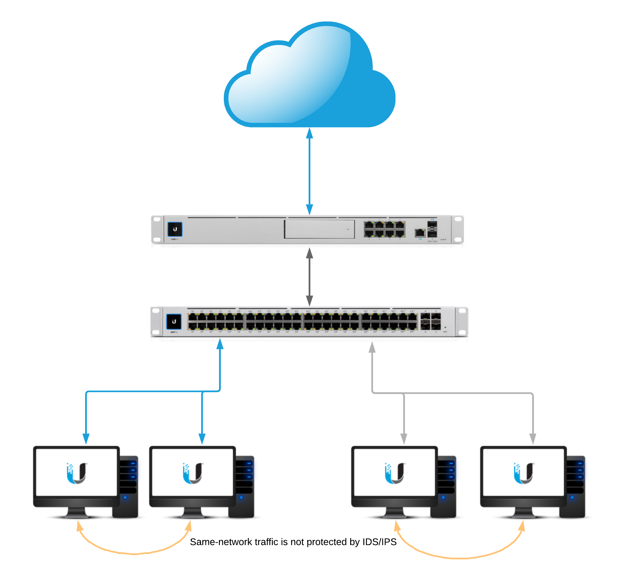
  2. Network Diagram
  3. Intrusion Detection and Prevention
    1. Categories
    2. Whitelisting
    3. Signature Suppression 
  4. GeoIP Filtering
  5. DNS Filters 
    1. Filter Levels
  6. Deep Packet Inspection
    1. DPI Restrictions (Layer 7 Filters)
  7. Network Scanners
    1. Internal Honeypot
      1. Honeypot Services
  8. Testing & Verification
  9. Privacy Statement
  10. Related Articles

Introduction

An intrusion prevention system (IPS) is an engine that identifies potentially malicious traffic based on signatures. The signatures contain known traffic patterns or instruction sequences used by malware. This type of signature-based engine can only detect anomalies based on known malicious traffic patterns.

Network Diagram

idsIps.png

Intrusion Detection and Prevention

To enable intrusion detection or intrusion prevention, navigate to the Settings > Security section of the UniFi Network application. ATTENTION:

  • Enabling IDS or IPS will affect the maximum throughput on inter-VLAN and egress traffic.
    • USG: 85 Mbps*
    • USG-Pro: 250 Mbps*
    • USG-XG: 1 Gbps*
  • Enabling Smart Queues or DPI on top of IPS/IDS will also incur a further throughput penalty to maximum throughput.
  • UniFi Dream Machine throughput: 850 Mbps*
  • UniFi Dream Machine Pro: 3.5Gbps*

*Values are rough estimates and can vary depending on configuration.

Threat Management Modes

  • Intrusion Detection System: When set will automatically detect, and alert, but will not block potentially malicious traffic. 
  • Intrusion Prevention System: When set will automatically detect, alert, and block potentially malicious traffic. 

Firewall Restrictions

These restrictions can be found under New Settings > Internet Security > Advanced.

  • Restrict Access to ToR: When enabled will block access to The Onion Router. 
  • Restrict Access to Malicious IP Addresses: When enabled will block access to IP addresses or blocks of addresses that have been recognized as passing malicious traffic. 

System Sensitivity Levels

mceclip3.png

The “system sensitivity levels” are pre-defined levels of security categories that will be loaded into the threat management daemon. Each level increase requires more memory and CPU usage. Additionally the “custom” level is utilized when manually selection categories.

Categories

ATTENTION:

  • Due to the amount of available memory on the USG3 and UDM a limited selection of categories can be enabled.
  • Click below to see a full list of categories.

Categories and Their Definitions

Click Here to Expand the IPS/IDS Categories Section

NOTE:The following configuration can be found in the Advanced tab of Internet Security.

Whitelisting

The Threat Management Allow List function of the IPS engine allows a UniFi Administrator to create a list of trusted IP’s. The traffic, depending on the direction selected, will not get blocked to or from the identified IPs. 

Create a new allow list within Settings > Security > Internet Threat Management > Advanced.

Signature Suppression

The signature suppression function of the IPS engine allows a UniFi Administrator to mute the alerting on certain signatures. This will also disable blocking on traffic matching the designated suppression rule. 

mceclip2.png
  • Adding a signature suppression rule for all traffic will suppress the signature regardless of host IP. 
  • Adding a signature suppression rule with packet tracking based on traffic direction and by single IP, defined UniFi Network, or subnet of choice. 

GeoIP Filtering

NOTE:For GeoIP Filtering to work on the USG, hardware offloading must be enabled. When Threat Management is enabled (under Settings > Internet Security > Threat Management), hardware offloading is disabled. Only one of these two features can be enabled at a time on the USG.

Blocking

Blocking individual countries can be configured on the Threat Management Dashboard section. Blocking is as easy as navigating to the map, clicking on a country, and confirming by clicking “Block”.

mceclip0.png

Unblocking

Unblocking a country can be by performed on the Threat Management Dashboard by navigating to the left side of the map on the Overview tab. A list of blocked countries will be populated. Simply hover over the county that is to be unblocked and an “unblock” option will appear. Select “unblock” and the country will be taken off of the list. 

mceclip1.png

Traffic Direction

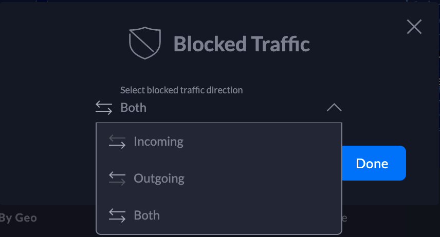
UniFi Network allows configuring the GeoIP filtering traffic direction. Follow the steps below:

    1. Navigate to the top of the Threat Management Dashboard and select the direction. Screen_Shot_2019-11-21_at_3.58.16_PM.png

    2. Select the traffic direction.

Screen_Shot_2019-11-21_at_4.00.26_PM.png

    3. Click Done.

DNS Filters

ATTENTION:

  • DNS Filtering is only available on the UniFi Dream Machine. 
  • Clients that use VPN, DNS-over-HTTPS, or DNS-over-TLS will have non-standard DNS requests that will not be seen by the UniFi Dream Machine. 

The DNS Filter feature allows administrators to select levels of filtering per-network. This ensures that any DNS requests that go out from clients on configured LANs adhere to the filtering levels. 

    1. To configure DNS Filters, navigate to New Settings > Internet Security > DNS Filters.

mceclip0.png

    2. Enable DNS Filtering by clicking the slider button.

    3. Select Add Filter.

    4. Choose the desired level of filtering for the LAN. 

    5. Select which network this filter should apply to and confirm the selection. 

    6. DNS filtering will be enabled at this point. 

Filter Levels

Security

Blocks access to phishing, spam, malware, and malicious domains. The database of malicious domains is updated hourly. Note that it does not block adult content.

Adult

Blocks access to all adult, pornographic and explicit sites. It does not block proxy or VPNs, nor mixed-content sites. Sites like Reddit are allowed. Google and Bing are set to the “Safe Mode”. Malicious and Phishing domains are blocked.

Family

Blocks access to all adult, pornographic and explicit sites. It also blocks proxy and VPN domains that are used to bypass the filters. Mixed content sites (like Reddit) are also blocked. Google, Bing, and Youtube are set to the Safe Mode. Malicious and Phishing domains are blocked.

Deep Packet Inspection

To configure Deep Packet Inspection (DPI) navigate to New Settings > Internet Security > Deep Packet Inspection.

mceclip1.png

NOTE: Device fingerprinting is not available on the UniFi Security Gateway.

DPI Restrictions

ATTENTION:DPI restrictions are limited to whole-category selections on the UniFi Security Gateway. This restriction is not applicable to the UniFi Dream Machine platform. 

    1. Click Add Restriction under “Restriction definitions”.

    2. In the configuration side-panel select a restriction group to add the rules to.

    3. Select a category to block. 

    4. Select an application from the category or select “All applications” to block the entire category.

    5. Ensure that “Enable This Restriction” is selected.

    6. Add the restriction group to a network in the “Restriction assignments” section. NOTE:A restriction definition can be applied to many networks. A restriction definition for each network is not required.

To manage the restriction definition, hover over the definition and selection either edit or remove.

mceclip2.png

Configuring Network Scanners

ATTENTION:Network Scanners are only available on the UniFi Dream Machine. 

Internal Honeypot

The “internal honeypot” feature is a passive detection system that listens for LAN clients attempting to gain access to unauthorized services or hosts. Clients that are potentially infected with worm or exfiltration type vulnerabilities are known to scan networks, infect other hosts, and potentially snoop for information on easy-to-access servers. The honeypot will report when hosts attempt to access the honeypot. Reports can be found on the Threat Management Dashboard.

To configure the internal honeypot follow the steps below:

    1. Navigate to Settings > Security > Internet Threat Management > Network Scanners.

settings.security.internet_threat_management.network_scanners.png

    2. Enable the honeypot service by clicking the slider button.

    3. Select “Create Honeypot”.

    4. In  the popup modal select the network and Honeypot IP.

    5. Select “Create”.

Honeypot Services

The honeypot service listens on the following ports:

  • FTP – TCP Port 21
  • SSH – TCP Port 22
  • Telnet – TCP Port 23
  • SMTP – TCP Port 25
  • DNS – UDP Port 53
  • HTTP – TCP Port 80
  • POP3 – TCP Port 110
  • SMB – TCP Port 445
  • MSSQL – TCP Port 1433

Testing & Verification

Intrusion Detection/Prevention

Linux or macOS

Input:

curl -A "BlackSun" www.example.com

Expected alert result:

Threat Management Alert 1: A Network Trojan was Detected. Signature ET USER_AGENTS Suspicious User Agent (BlackSun). From: 192.168.1.172:55693, to:172.217.4.196:80, protocol: TCP

Windows

The DNS category must be enabled

Input:

nslookup blacklistthisdomain.com 8.8.8.8

Expected alert result:

Threat Management Alert 1: A Network Trojan was Detected. Signature ET DNS Reply Sinkhole - 106.187.96.49 blacklistthisdomain.com. From: 192.168.1.1:53, to: 192.168.1.182:61440, protocol: UDP

Internal Honeypot

A few examples of manually testing the internal honeypot service are below. The following commands may or may not prompt for login credentials. The alerts will appear in the Honeypot section of the Threat Management Dashboard a few minutes after attempting the testing.

Telnet:

telnet <honeypot_ip>

SSH:

ssh <honeypot_ip>

NOTE:Replace <honeypot_ip> with the honeypot IP configured in the UniFi Network application.

Privacy Statement

What information does the IPS/IDS engine send to the cloud?

1. When a UniFi Administrator enables IPS or IDS on the UniFi Network application a token is generated for the gateway. The information listed below is sent over a TLS 1.2 encrypted connection whenever there is an IPS/IDS signature match.

timestamp
interface
source IP
source port
destination IP
destination port
protocol
signature id

2. Every 120-seconds there is a keep-alive to the ips1.unifi-ai.com hostname. This connection is to ensure reliable delivery of the violation message. The keep-alive is a connection to our cloud using port 443 so it is not just an ICMP ping or DNS resolution but a complete 3-way handshake and SSL Key exchange.

What information is kept on our servers regarding IPS/IDS?

The data listed above is only temporarily stored in the IPS Cloud until the  UniFi Network application downloads the information. After the information is downloaded by the application, the data is deleted from our cloud except for the attacker IP. The attacker IP information helps Ubiquiti maintain an up-to-date and effective attacker list which will improve Ubiquiti’s services to Ubiquiti customers around the world.

How is the information from alerts used by Ubiquiti?

Ubiquiti will use the alert information to improve its products and services, including generating lists of IP Reputation, Malicious IP addresses, Threat Intelligence and creating blacklists and new signatures for Ubiquiti devices. A sanitized version of IP addresses  (Ex: 200.200.x.x) can also be displayed on Ubiquiti Public Threat Map to help the public community to see malicious traffic around the world.

Source :
https://help.ui.com/hc/en-us/articles/360006893234-UniFi-USG-UDM-Configuring-Internet-Security-Settings