The “License of HA Pair doesn’t match” or “HA License Sync Error” log message will repeat every 15 minutes if licensing of the Primary and Backup firewalls is not equivalent. This message is intended to alert the firewall administrator that not all services configured on the Primary will be active on the Backup firewall.
For example: The error message may occur if the number of Network Anti-Virus licenses are different on the Primary and Backup appliances, or, if the Primary has Content Filtering Service (CFS) but the Backup does not, there will be no CFS functionality if the Backup becomes the active firewall.
Resolution for SonicOS 7.X
This release includes significant user interface changes and many new features that are different from the SonicOS 6.5 and earlier firmware. The below resolution is for customers using SonicOS 7.X firmware.
Step 1: Synchronize the licenses on both the devices.
Log into the Backup SonicWall’s unique LAN IP address. The management interface should now display Logged Into: Secondary Device in the upper left corner. If all licenses are not already synchronized with the Primary unit, follow these steps:
Navigate to the Device | Settings | Licenses page and click Synchronize in the upper right corner.
From the Device | Diagnostics | DNS Name Lookup page, use the “Lookup Name or IP” option to see if the DNS servers listed in the SonicWall WAN Interface are resolving the license manager URL “licensemanager.SonicWall.com” on both units. TIP: If the DNS servers are not resolving, try changing the DNS IP addresses on the SonicWall WAN Interface and then try to synchronize the licenses.
If the backup unit is not registered, navigate to the Device | Settings | Licenses page and register the SonicWall security appliance on mySonicWall.com. This allows the SonicWall licensing server to synchronize the licenses.
Step 2: Verify the licenses on www.mySonicWall.com
To use the High Availability feature, you must register both the SonicWall appliances on mySonicWall.com as Associated Products.
Both appliances must be the same SonicWall model,
Must be registered under the same mySonicWall.com user account,
And must be separately licensed for SonicOS Enhanced.
NOTE: The SonicOS Enhanced license is not shareable between the primary and the backup appliances. Both appliances must be licensed separately.
Verify the HA Secondary device on mySonicWall.com account:
Click on the Primary UTM appliance (e.g. TZ 670) and scroll down to Associated Products section.
Click on High Availability Secondary and ensure that the Serial number of device matches with the Backup SonicWall entry on the Devices | High Availability | Settings page of your Primary SonicWall appliance.
Please Note that the backup appliance of your high availability pair is referred to as the HA Secondary unit on mySonicWall.com. After the appliances are associated as an HA Pair, they can share licenses.
Step 3: Adding secondary UTM appliance under the HA pair on mySonicWall.com
If you have not registered/Associated the HA Secondary device on the mySonicWall.com, follow these steps:
Registering the Secondary/Backup UTM appliance from the SonicWall Management Interface
Important: After registering new SonicWall appliances on mySonicWall.com, you must also register the backup appliance from the SonicOS management interface while logged into its individual management IP address. This allows the backup unit to synchronize with the SonicWall license server (licensemanager.SonicWall.com) and share licenses with the associated primary appliance.
Step 4: Accessing the Secondary UTM appliance and Synchronizing the Licenses
On the Device |High Availability | Monitoring page, you can configure unique management IP addresses for both units in the HA Pair which allows you to log in to each unit independently for management purposes. See also Configuring High Availability Monitoring settings
Also you can configure Logical/Probe IP addressfor SonicWall to monitor a reliable device on one or more of the connected networks. Failure to periodically communicate with the device by the Active unit in the HA Pair will trigger a failover to the Idle unit. If neither unit in the HA Pair can connect to the device, no action will be taken.
NOTE: The Primary IP Address and Backup IP Address fields must be configured with independent IP addresses on a LAN interface, such as X0, (or a WAN interface, such as X1, for probing on the WAN) to allow logical probing to function correctly.
In the Logical Probe IP Address field, enter the IP address of a downstream device on the LAN network that should be monitored for connectivity. Typically, this should be a downstream router or server. (If probing is desired on the WAN side, an upstream device should be used.) The Primary and Backup appliances will regularly ping this probe IP address. If both can successfully ping the target, no failover occurs. If neither can successfully ping the target, no failover occurs, because it is assumed that the problem is with the target, and not the SonicWall appliances. But, if one appliance can ping the target but the other appliance cannot, failover will occur to the appliance that can ping the target.
Step 5: Try to synchronize the licenses again on both the devices.
Step 6: You may also try to upgrade the firmware to the latest version and try to synchronize the licenses again.
This release includes significant user interface changes and many new features that are different from the SonicOS 6.2 and earlier firmware. The below resolution is for customers using SonicOS 6.5 firmware.
Step 1: Synchronize the licenses on both the devices.
Log into the Backup SonicWall’s unique LAN IP address. The management interface should now display Logged Into: Backup SonicWall Status: (green ball) Active in the upper right corner. If all licenses are not already synchronized with the Primary unit, follow these steps:
Navigate to the Manage | Licenses page and click Synchronize.
From the Investigate | Tools | System Diagnostics page, use the “DNS Name Lookup” option under Diagnostic Tool drop down menu to see if the DNS servers listed in the SonicWall WAN Interface are resolving the license manager URL “licensemanager.SonicWall.com” on both units. TIP: If the DNS servers are not resolving, try changing the DNS IP addresses on the SonicWall WAN Interface and then try to synchronize the licenses.
If the backup unit is not registered, navigate to the Manage | Licenses page and register the SonicWall security appliance on mySonicWall.com. This allows the SonicWall licensing server to synchronize the licenses.
Step 2: Verify the licenses on www.mySonicWall.com
To use the High Availability feature, you must register both the SonicWall appliances on mySonicWall.com as Associated Products.
Both appliances must be the same SonicWall model,
Must be registered under the same mySonicWall.com user account,
And must be separately licensed for SonicOS Enhanced.
NOTE: The SonicOS Enhanced license is not shareable between the primary and the backup appliances. Both appliances must be licensed separately.
Verify the HA Secondary device on mySonicWall.com account:
Click on the Primary UTM appliance (e.g. TZ 600) and scroll down to Associated Products section.
Click on High Availability Secondary and ensure that the Serial number of device matches with the Backup SonicWall entry on the Manage | High Availability | Base Setup | HA Devices page of your Primary SonicWall appliance.
Please Note that the backup appliance of your high availability pair is referred to as the HA Secondary unit on mySonicWall.com. After the appliances are associated as an HA Pair, they can share licenses.
Step 3: Adding secondary UTM appliance under the HA pair on mySonicWall.com
If you have not registered/Associated the HA Secondary device on the mySonicWall.com, follow these steps:
Registering the Secondary/Backup UTM appliance from the SonicWall Management Interface
Important: After registering new SonicWall appliances on mySonicWall.com, you must also register the backup appliance from the SonicOS management interface while logged into its individual management IP address. This allows the backup unit to synchronize with the SonicWall license server (licensemanager.SonicWall.com) and share licenses with the associated primary appliance.
Step 4: Accessing the Secondary UTM appliance and Synchronizing the Licenses
On the Manage |HighAvailability | Monitoring Settings page, you can configure unique management IP addresses for both units in the HA Pair which allows you to log in to each unit independently for management purposes. See also Configuring High Availability Monitoring settings.
Also you can configure Logical/Probe IP address for SonicWall to monitor a reliable device on one or more of the connected networks. Failure to periodically communicate with the device by the Active unit in the HA Pair will trigger a failover to the Idle unit. If neither unit in the HA Pair can connect to the device, no action will be taken.
NOTE: The Primary IP Address and Backup IP Address fields must be configured with independent IP addresses on a LAN interface, such as X0, (or a WAN interface, such as X1, for probing on the WAN) to allow logical probing to function correctly.
In the Logical Probe IP Address field, enter the IP address of a downstream device on the LAN network that should be monitored for connectivity. Typically, this should be a downstream router or server. (If probing is desired on the WAN side, an upstream device should be used.) The Primary and Backup appliances will regularly ping this probe IP address. If both can successfully ping the target, no failover occurs. If neither can successfully ping the target, no failover occurs, because it is assumed that the problem is with the target, and not the SonicWall appliances. But, if one appliance can ping the target but the other appliance cannot, failover will occur to the appliance that can ping the target.
Step 5: Try to synchronize the licenses again on both the devices.
Step 6: You may also try to upgrade the firmware to the latest version and try to synchronize the licenses again.
On the High Availability | Monitoring page, you can configure both physical and logical interface monitoring. By enabling physical interface monitoring, you enable link detection for the designated HA interfaces. The link is sensed at the physical layer to determine link viability. Logical monitoring involves configuring the SonicWall to monitor a reliable device on one or more of the connected networks. Failure to periodically communicate with the device by the Active unit in the HA Pair will trigger a Failover to the Idle unit. If neither unit in the HA Pair can connect to the device, no action will be taken.
The Primary and Backup IP addresses configured on this page are used for multiple purposes.
As independent management addresses for each unit (supported on all physical interfaces).
To allow synchronization of licenses between the Idle unit and the SonicWall licensing server .
As the source IP addresses for the probe pings sent out during logical monitoring.
When using logical monitoring, the HA Pair will ping the specified Logical Probe IP address target from the Primary as well as from the Backup SonicWall. The IP address set in the Primary IP Address or Backup IP Address field is used as the source IP address for the ping. If both units can successfully ping the target, no Failover occurs. If both cannot successfully ping the target, no Failover occurs, as the SonicWalls will assume that the problem is with the target, and not the SonicWalls. But, if one SonicWall can ping the target but the other SonicWall cannot, the HA Pair will Failover to the SonicWall that can ping the target.
Resolution for SonicOS 7.X
This release includes significant user interface changes and many new features that are different from the SonicOS 6.5 and earlier firmware. The below resolution is for customers using SonicOS 7.X firmware.
The configuration tasks on the High Availability |Monitoring page are performed on the Primary unit and then are automatically synchronized to the Backup.
Login as an administrator to the SonicOS user interface on the Primary SonicWall.
Go to Device In top menu , navigate to High Availability | Monitoring Settings .
Click Configure icon for an interface on the LAN, such as X0.
To enable link detection between the designated HA interfaces on the Primary and Backup units, leave the Enable Physical / Link Monitoring checkbox selected.
In the Primary IP Address field, enter the unique LAN management IP address of the Primary unit.
In the Backup IP Address field, enter the unique LAN management IP address of the Backup unit.
Configuring unique management IP addresses for both units in the HA Pair allows you to log in to each unit independently for management purposes. Note that non-management traffic is ignored if it is sent to one of these IP addresses. The Primary and Backup SonicWall security appliances’ unique LAN IP addresses cannot act as an active gateway; all systems connected to the internal LAN will need to use the virtual LAN IP address as their gateway.
The management IP address of the Backup/Idle unit is used to allow license synchronization with the SonicWall licensing server, which handles licensing on a per-appliance basis (not per-HA Pair). Even if the Backup unit was already registered on MySonicWall before creating the HA association, you must use the link on the Device | Settings | Licenses page to connect to the SonicWall server while accessing the Backup appliance through its management IP address.
Select the Allow Management on Primary/Backup IP Address checkbox. When this option is enabled for an interface, a green icon appears in the interface’s management column in the Monitoring Settings table on the High Availability | Monitoring page. Management is only allowed on an interface when this option is enabled.
In the Logical Probe IP Address field, enter the IP address of a downstream device on the LAN network that should be monitored for connectivity.Typically, this should be a downstream router or server. (If probing is desired on the WAN side, an upstream device should be used.) The Primary and Backup appliances will regularly ping this probe IP address. If both can successfully ping the target, no failover occurs. If neither can successfully ping the target, no failover occurs, because it is assumed that the problem is with the target, and not the SonicWall appliances. But, if one appliance can ping the target but the other appliance cannot, failover will occur to the appliance that can ping the target.
NOTE: The Primary IP Address and Backup IP Address fields must be configured with independent IP addresses on a LAN interface, such as X0, (or a WAN interface, such as X1, for probing on the WAN) to allow logical probing to function correctly.
Optionally, to manually specify the virtual MAC address for the interface, select Override Virtual MAC and enter the MAC address in the field. The format for the MAC address is six pairs of hexadecimal numbers separated by colons, such as A1:B2:C3:d4:e5:f6. Care must be taken when choosing the Virtual MAC address to prevent configuration errors.
Note:There is a design change on Gen7 in the way MAC Addresses are handled for the HA native vs. monitoring. GEN7 uses the Virtual MAC for all interface IPs, both the Virtual IPs and Primary / Secondary Monitoring IPs, Hence the MAC addresses of the X0 Interface IP(Or any VLAN under X0), will have the same MAC address as of the Primary firewall X0 monitoring IP, the same applies for all the interfaces X1, X2, wherever monitoring IPs will be configured.
To configure monitoring on any of the other interfaces, repeat the above steps.
When finished with all High Availability configuration, click Accept. All settings will be synchronized to the Idle unit automatically.
Resolution for SonicOS 6.5
This release includes significant user interface changes and many new features that are different from the SonicOS 6.2 and earlier firmware. The below resolution is for customers using SonicOS 6.5 firmware.
The configuration tasks on the High Availability |Monitoring page are performed on the Primary unit and then are automatically synchronized to the Backup.
Login as an administrator to the SonicOS user interface on the Primary SonicWall.
Go to Manage In top menu , navigate to High Availability | Monitoring Settings .
Click Configure icon for an interface on the LAN, such as X0.
To enable link detection between the designated HA interfaces on the Primary and Backup units, leave the Enable Physical / Link Monitoring checkbox selected.
In the Primary IP Address field, enter the unique LAN management IP address of the Primary unit.
In the Backup IP Address field, enter the unique LAN management IP address of the Backup unit.
Configuring unique management IP addresses for both units in the HA Pair allows you to log in to each unit independently for management purposes. Note that non-management traffic is ignored if it is sent to one of these IP addresses. The Primary and Backup SonicWall security appliances’ unique LAN IP addresses cannot act as an active gateway; all systems connected to the internal LAN will need to use the virtual LAN IP address as their gateway.
The management IP address of the Backup/Idle unit is used to allow license synchronization with the SonicWall licensing server, which handles licensing on a per-appliance basis (not per-HA Pair). Even if the Backup unit was already registered on MySonicWall before creating the HA association, you must use the link on the System | Licenses page to connect to the SonicWall server while accessing the Backup appliance through its management IP address.
Select the Allow Management on Primary/Backup IP Address checkbox. When this option is enabled for an interface, a green icon appears in the interface’s management column in the Monitoring Settings table on the High Availability | Monitoring page. Management is only allowed on an interface when this option is enabled.
In the Logical Probe IP Address field, enter the IP address of a downstream device on the LAN network that should be monitored for connectivity.Typically, this should be a downstream router or server. (If probing is desired on the WAN side, an upstream device should be used.) The Primary and Backup appliances will regularly ping this probe IP address. If both can successfully ping the target, no failover occurs. If neither can successfully ping the target, no failover occurs, because it is assumed that the problem is with the target, and not the SonicWall appliances. But, if one appliance can ping the target but the other appliance cannot, failover will occur to the appliance that can ping the target.
NOTE: The Primary IP Address and Backup IP Address fields must be configured with independent IP addresses on a LAN interface, such as X0, (or a WAN interface, such as X1, for probing on the WAN) to allow logical probing to function correctly.
Optionally, to manually specify the virtual MAC address for the interface, select Override Virtual MAC and enter the MAC address in the field. The format for the MAC address is six pairs of hexadecimal numbers separated by colons, such as A1:B2:C3:d4:e5:f6. Care must be taken when choosing the Virtual MAC address to prevent configuration errors.When the Enable Virtual MAC checkbox is selected on the Manage |High Availability| Base Setup page, the SonicOS firmware automatically generates a Virtual MAC address for all interfaces. Allowing the SonicOS firmware to generate the Virtual MAC address eliminates the possibility of configuration errors and ensures the uniqueness of the Virtual MAC address, which prevents possible conflicts.
To configure monitoring on any of the other interfaces, repeat the above steps.
When finished with all High Availability configuration, click Accept. All settings will be synchronized to the Idle unit automatically.
Resolution for SonicOS 6.2 and Below
The below resolution is for customers using SonicOS 6.2 and earlier firmware. For firewalls that are generation 6 and newer we suggest to upgrade to the latest general release of SonicOS 6.5 firmware.
The configuration tasks on the High Availability |Monitoring page are performed on the Primary unit and then are automatically synchronized to the Backup.
Login as an administrator to the SonicOS user interface on the Primary SonicWall.
In the left navigation pane, navigate to High Availability | Monitoring.
Click Configure icon for an interface on the LAN, such as X0.
To enable link detection between the designated HA interfaces on the Primary and Backup units, leave the Enable Physical Interface Monitoring checkbox selected.
In the Primary IP Address field, enter the unique LAN management IP address of the Primary unit.
In the Backup IP Address field, enter the unique LAN management IP address of the Backup unit.
Configuring unique management IP addresses for both units in the HA Pair allows you to log in to each unit independently for management purposes. Note that non-management traffic is ignored if it is sent to one of these IP addresses. The Primary and Backup SonicWall security appliances’ unique LAN IP addresses cannot act as an active gateway; all systems connected to the internal LAN will need to use the virtual LAN IP address as their gateway.
The management IP address of the Backup/Idle unit is used to allow license synchronization with the SonicWall licensing server, which handles licensing on a per-appliance basis (not per-HA Pair). Even if the Backup unit was already registered on MySonicWall before creating the HA association, you must use the link on the System | Licenses page to connect to the SonicWall server while accessing the Backup appliance through its management IP address.
Select the Allow Management on Primary/Backup IP Address checkbox. When this option is enabled for an interface, a green icon appears in the interface’s Management column in the Monitoring Settings table on the High Availability | Monitoring page. Management is only allowed on an interface when this option is enabled.
In the Logical Probe IP Address field, enter the IP address of a downstream device on the LAN network that should be monitored for connectivity.Typically, this should be a downstream router or server. (If probing is desired on the WAN side, an upstream device should be used.) The Primary and Backup appliances will regularly ping this probe IP address. If both can successfully ping the target, no failover occurs. If neither can successfully ping the target, no failover occurs, because it is assumed that the problem is with the target, and not the SonicWall appliances. But, if one appliance can ping the target but the other appliance cannot, failover will occur to the appliance that can ping the target.
NOTE:The Primary IP Address and Backup IP Address fields must be configured with independent IP addresses on a LAN interface, such as X0, (or a WAN interface, such as X1, for probing on the WAN) to allow logical probing to function correctly.
Optionally, to manually specify the virtual MAC address for the interface, select Override Virtual MAC and enter the MAC address in the field. The format for the MAC address is six pairs of hexadecimal numbers separated by colons, such as A1:B2:C3:d4:e5:f6. Care must be taken when choosing the Virtual MAC address to prevent configuration errors.When the Enable Virtual MAC checkbox is selected on the High Availability| Advanced page, the SonicOS firmware automatically generates a Virtual MAC address for all interfaces. Allowing the SonicOS firmware to generate the Virtual MAC address eliminates the possibility of configuration errors and ensures the uniqueness of the Virtual MAC address, which prevents possible conflicts.
Click OK.
To configure monitoring on any of the other interfaces, repeat the above steps.
When finished with all High Availability configuration, click Accept. All settings will be synchronized to the Idle unit automatically.
As part of our ongoing commitment to security, we are discontinuing support for the TLS 1.0 and TLS 1.1 encryption protocols in our license manager. This will cause GEN 5 and GEN 6 firewalls running older firmware to not communicate with the license manager leading to licensing issues. The firewall will not be able to validate its license or obtain necessary updates resulting in a licensing failure. The firewall will operate with reduced functionality or disable certain advanced features that require periodic license validation or updates.
Examples of services that will no longer function properly include:
Capture Advanced Threat Protection
Gateway Anti-Malware
Intrusion Prevention
Application Control
These licensed features will no longer work as expected. Critical security updates, threat intelligence updates, or other important updates may not be applied, potentially leaving the network vulnerable to emerging threats.
Discontinuing TLS 1.0 and TLS 1.1 is in line with industry best practices and aims to enhance the security of data transmission between your systems and our servers. To ensure uninterrupted service and data security, it’s important to upgrade your firewall to use TLS 1.2 or higher.
Product Impact
All GEN 5 and GEN 6 appliances running an older firmware will be affected when support for TLS 1.0 and TLS 1.1 encryption protocols are disabled.
Remediation
SonicWall strongly recommends upgrading the firewall’s firmware to the latest version to maintain a secure connection with our license manager, as the latest firmware has the support of encryption protocols TLS 1.2 or later.
Impacted Platforms
Recommended Firmware Version
Minimum Firmware Version
Gen 5
SonicOS 5.9.2.13
SonicOS 5.9.2.x
Gen 6
SonicOS 6.5.4.12-101n
SonicOS 6.2.9.x
Timeline
The support for TLS 1.0 and TLS 1.1 will be disabled on October 31, 2023. After this date, connections using these protocols will be rejected by our license manager.
Ensure that your systems are upgraded and ready to use TLS 1.2 or higher before the mentioned date to prevent disruption of service.
Product Migration Option
SonicWall has released the GEN 7 hardware which has been designed to take your experience to new heights, offering unparalleled performance, stunning visuals, and cutting-edge features that will revolutionize the way you interact with our products. As SonicWall customers you are eligible for the secure upgrade to the next generation of hardware. For details, please review our Secure upgrade program
NOTE: If you do not have an active support contract or need assistance on GEN 7 upgrade options, please contact renewals@sonicwall.com. If you have any questions about the process, please do not hesitate to contact SonicWall support for assistance. Our support team is available to provide guidance and address any concerns you may have.
By: Salim S.I. September 20, 2023 Read time: 8 min (2105 words)
Crafted packets from cellular devices such as mobile phones can exploit faulty state machines in the 5G core to attack cellular infrastructure. Smart devices that critical industries such as defense, utilities, and the medical sectors use for their daily operations depend on the speed, efficiency, and productivity brought by 5G. This entry describes CVE-2021-45462 as a potential use case to deploy a denial-of-service (DoS) attack to private 5G networks.
5G unlocks unprecedented applications previously unreachable with conventional wireless connectivity to help enterprises accelerate digital transformation, reduce operational costs, and maximize productivity for the best return on investments. To achieve its goals, 5G relies on key service categories: massive machine-type communications (mMTC), enhanced mobile broadband (eMBB), and ultra-reliable low-latency communication (uRLLC).
With the growing spectrum for commercial use, usage and popularization of private 5G networks are on the rise. The manufacturing, defense, ports, energy, logistics, and mining industries are just some of the earliest adopters of these private networks, especially for companies rapidly leaning on the internet of things (IoT) for digitizing production systems and supply chains. Unlike public grids, the cellular infrastructure equipment in private 5G might be owned and operated by the user-enterprise themselves, system integrators, or by carriers. However, given the growing study and exploration of the use of 5G for the development of various technologies, cybercriminals are also looking into exploiting the threats and risks that can be used to intrude into the systems and networks of both users and organizations via this new communication standard. This entry explores how normal user devices can be abused in relation to 5G’s network infrastructure and use cases.
5G topology
In an end-to-end 5G cellular system, user equipment (aka UE, such as mobile phones and internet-of-things [IoT] devices), connect to a base station via radio waves. The base station is connected to the 5G core through a wired IP network.
Functionally, the 5G core can be split into two: the control plane and the user plane. In the network, the control plane carries the signals and facilitates the traffic based on how it is exchanged from one endpoint to another. Meanwhile, the user plane functions to connect and process the user data that comes over the radio area network (RAN).
The base station sends control signals related to device attachment and establishes the connection to the control plane via NGAP (Next-Generation Application Protocol). The user traffic from devices is sent to the user plane using GTP-U (GPRS tunneling protocol user plane). From the user plane, the data traffic is routed to the external network.
Figure 1. The basic 5G network infrastructure
The UE subnet and infrastructure network are separate and isolated from each other; user equipment is not allowed to access infrastructure components. This isolation helps protect the 5G core from CT (Cellular Technology) protocol attacks generated from users’ equipment.
Is there a way to get past this isolation and attack the 5G core? The next sections elaborate on the how cybercriminals could abuse components of the 5G infrastructure, particularly the GTP-U.
GTP-U
GTP-U is a tunneling protocol that exists between the base station and 5G user plane using port 2152. The following is the structure of a user data packet encapsulated in GTP-U.
Figure 2. GTP-U data packet
A GTP-U tunnel packet is created by attaching a header to the original data packet. The added header consists of a UDP (User Datagram Protocol) transport header plus a GTP-U specific header. The GTP-U header consists of the following fields:
Flags: This contains the version and other information (such as an indication of whether optional header fields are present, among others).
Message type: For GTP-U packet carrying user data, the message type is 0xFF.
Length: This is the length in bytes of everything that comes after the Tunnel Endpoint Identifier (TEID) field.
TEID: Unique value for a tunnel that maps the tunnel to user devices
The GTP-U header is added by the GTP-U nodes (the base station and User Plane Function or UPF). However, the user cannot see the header on the user interface of the device. Therefore, user devices cannot manipulate the header fields.
Although GTP-U is a standard tunneling technique, its use is mostly restricted to CT environments between the base station and the UPF or between UPFs. Assuming the best scenario, the backhaul between the base station and the UPF is encrypted, protected by a firewall, and closed to outside access. Here is a breakdown of the ideal scenario: GSMArecommends IP security (IPsec) between the base station and the UPF. In such a scenario, packets going to the GTP-U nodes come from authorized devices only. If these devices follow specifications and implement them well, none of them will send anomalous packets. Besides, robust systems are expected to have strong sanity checks to handle received anomalies, especially obvious ones such as invalid lengths, types, and extensions, among others.
In reality, however, the scenario could often be different and would require a different analysis altogether. Operators are reluctant to deploy IPsec on the N3 interface because it is CPU-intensive and reduces the throughput of user traffic. Also, since the user data is perceived to be protected at the application layer (with additional protocols such as TLS or Transport Layer Security), some consider IP security redundant. One might think that for as long as the base station and packet-core conform to the specific, there will be no anomalies. Besides, one might also think that for all robust systems require sanity checks to catch any obvious anomalies. However, previous studies have shown that many N3 nodes (such as UPF) around the world, although they should not be, are exposed to the internet. This is shown in the following sections.
Figure 3. Exposed UPF interfaces due to misconfigurations or lack of firewalls; screenshot taken from Shodan and used in a previously published research
We discuss two concepts that can exploit the GTP-U using CVE-2021-45462. In Open5GS, a C-language open-source implementation for 5G Core and Evolved Packet Core (EPC), sending a zero-length, type=255 GTP-U packet from the user device resulted in a denial of service (DoS) of the UPF. This is CVE-2021-45462, a security gap in the packet core that can crash the UPF (in 5G) or Serving Gateway User Plane Function (SGW-U in 4G/LTE) via an anomalous GTP-U packet crafted from the UE and by sending this anomalous GTP-U packet in the GTP-U. Given that the exploit affects a critical component of the infrastructure and cannot be resolved as easily, the vulnerability has received a Medium to High severity rating.
GTP-U nodes: Base station and UPF
GTP-U nodes are endpoints that encapsulate and decapsulate GTP-U packets. The base station is the GTP-U node on the user device side. As the base station receives user data from the UE, it converts the data to IP packets and encapsulates it in the GTP-U tunnel.
The UPF is the GTP-U node on the 5G core (5GC) side. When it receives a GTP-U packet from the base station, the UPF decapsulates the outer GTP-U header and takes out the inner packet. The UPF looks up the destination IP address in a routing table (also maintained by the UPF) without checking the content of the inner packet, after which the packet is sent on its way.
GTP-U in GTP-U
What if a user device crafts an anomalous GTP-U packet and sends it to a packet core?
Figure 4. A specially crafted anomalous GTP-U packetFigure 5. Sending an anomalous GTP-U packet from the user device
As intended, the base station will tunnel this packet inside its GTP-U tunnel and send to the UPF. This results in a GTP-U in the GTP-U packet arriving at the UPF. There are now two GTP-U packets in the UPF: The outer GTP-U packet header is created by the base station to encapsulate the data packet from the user device. This outer GTP-U packet has 0xFF as its message type and a length of 44. This header is normal. The inner GTP-U header is crafted and sent by the user device as a data packet. Like the outer one, this inner GTP-U has 0xFF as message type, but a length of 0 is not normal.
The source IP address of the inner packet belongs to the user device, while the source IP address of the outer packet belongs to the base station. Both inner and outer packets have the same destination IP address: that of the UPF.
The UPF decapsulates the outer GTP-U and passes the functional checks. The inner GTP-U packet’s destination is again the same UPF. What happens next is implementation-specific:
Some implementations maintain a state machine for packet traversal. Improper implementation of the state machine might result in processing this inner GTP-U packet. This packet might have passed the checks phase already since it shares the same packet-context with the outer packet. This leads to having an anomalous packet inside the system, past sanity checks.
Since the inner packet’s destination is the IP address of UPF itself, the packet might get sent to the UPF. In this case, the packet is likely to hit the functional checks and therefore becomes less problematic than the previous case.
Attack vector
Some 5G core vendors leverage Open5GS code. For example, NextEPC (4G system, rebranded as Open5GS in 2019 to add 5G, with remaining products from the old brand) has an enterprise offer for LTE/5G, which draws from Open5GS’ code. No attacks or indications of threats in the wild have been observed, but our tests indicate potential risks using the identified scenarios.
The importance of the attack is in the attack vector: the cellular infrastructure attacks from the UE. The exploit only requires a mobile phone (or a computer connected via a cellular dongle) and a few lines of Python code to abuse the opening and mount this class of attack. The GTP-U in GTP-U attacks is a well-knowntechnique, and backhaul IP security and encryption do not prevent this attack. In fact, these security measures might hinder the firewall from inspecting the content.
Remediation and insights
Critical industries such as the medical and utility sectors are just some of the early adopters of private 5G systems, and its breadth and depth of popular use are only expected to grow further. Reliability for continuous, uninterrupted operations is critical for these industries as there are lives and real-world implications at stake. The foundational function of these sectors are the reason that they choose to use a private 5G system over Wi-Fi. It is imperative that private 5G systems offer unfailing connectivity as a successful attack on any 5G infrastructure could bring the entire network down.
In this entry, the abuse of CVE-2021-45462 can result in a DoS attack. The root cause of CVE-2021-45462 (and most GTP-U-in-GTP-U attacks) is the improper error checking and error handling in the packet core. While GTP-U-in-GTP-U itself is harmless, the proper fix for the gap has to come from the packet-core vendor, and infrastructure admins must use the latest versions of the software.
A GTP-U-in-GTP-U attack can also be used to leak sensitive information such as the IP addresses of infrastructure nodes. GTP-U peers should therefore be prepared to handle GTP-U-in-GTP-U packets. In CT environments, they should use an intrusion prevention system (IPS) or firewalls that can understand CT protocols. Since GTP-U is not normal user traffic, especially in private 5G, security teams can prioritize and drop GTP-U-in-GTP-U traffic.
As a general rule, the registration and use of SIM cards must be strictly regulated and managed. An attacker with a stolen SIM card could insert it to an attacker’s device to connect to a network for malicious deployments. Moreover, the responsibility of security might be ambiguous to some in a shared operating model, such as end-devices and the edge of the infrastructure chain owned by the enterprise. Meanwhile, the cellular infrastructure is owned by the integrator or carrier. This presents a hard task for security operation centers (SOCs) to bring relevant information together from different domains and solutions.
In addition, due to the downtime and tests required, updating critical infrastructure software regularly to keep up with vendor’s patches is not easy, nor will it ever be. Virtual patching with IPS or layered firewalls is thus strongly recommended. Fortunately, GTP-in-GTP is rarely used in real-world applications, so it might be safe to completely block all GTP-in-GTP traffic. We recommend using layered security solutions that combine IT and communications technology (CT) security and visibility. Implementing zero-trust solutions, such as Trend Micro™ Mobile Network Security, powered by CTOne, adds another security layer for enterprises and critical industries to prevent the unauthorized use of their respective private networks for a continuous and undisrupted industrial ecosystem, and by ensuring that the SIM is used only from an authorized device. Mobile Network Security also brings CT and IT security into a unified visibility and management console.
On October 2, 2023, (Non-US) D-Link Corporation was notified of a claim of data breach from an online forum by an unauthorized third party, indicating the theft of certain data. Upon becoming aware of this claim, the company promptly initiated a comprehensive investigation into the situation and immediately took precautionary measures. Currently, there is no impact on any of the D-Link operations.
Through internal and external investigations by experts from Trend Mirco, the company identified numerous inaccuracies and exaggerations in the claim that were intentionally misleading and did not align with facts. The data was confirmed not from the cloud but likely originated from an old D-View 6 system, which reached its end of life as early as 2015. The data was used for registration purposes back then. So far, no evidence suggests the archaic data contained any user IDs or financial information. However, some low-sensitivity and semi-public information, such as contact names or office email addresses, were indicated.
The incident is believed to have been triggered by an employee unintentionally falling victim to a phishing attack, resulting in unauthorized access to long-unused and outdated data. Despite the company’s systems meeting the information security standards of that era, it profoundly regrets this occurrence. D-Link is fully dedicated to addressing this incident and implementing measures to enhance the security of its business operations. After the incident, the company promptly terminated the services of the test lab and conducted a thorough review of the access control. Further steps will continue to be taken as necessary to safeguard the rights of all users in the future.
D-Link believes current customers are unlikely to be affected by this incident. However, please get in touch with local customer service for more information if anyone has concerns. D-Link takes information security seriously and has a dedicated task force and product management team on call to address evolving security issues and implement appropriate security measures. D-Link shall always endeavor to provide the best services to its customers.
l What happened?
On October 1, 2023, someone posted an article in an online forum and claimed that the D-View system, a software monitoring tool for local networking devices and network administrators, was breached, and millions of users’ data were stolen.
l Was there credibility in this claim?
There were numerous inaccuracies and exaggerations in this claim that did not align with the facts, including but not limited to:
– The amount of data: Believed to be approximately 700 records
We have reasons to believe the latest login timestamps were intentionally tampered with to make the archaic data look recent.
l When did the company take the necessary actions?
We initiated a comprehensive investigation into the claim and immediately took preventive measures on the same day we were informed.
l What measures has the company currently taken?
We immediately shut down presumably relevant servers after being informed of this incident. We blocked user accounts on the live systems, retaining only two maintenance accounts to investigate any signs of intrusion further. Simultaneously, we conducted multiple examinations to determine if any leaked backup data remained in the test lab environment and disconnected the test lab from the company’s internal network.
Subsequently, we will audit outdated user and backup data and proceed with their deletion to prevent a recurrence of similar incidents.
l What is the impact of this incident?
The post claimed to have millions of user data. Based on the investigations, however, it only contained approximately 700 outdated and fragmented records that had been inactive for at least seven years. These records originated from a product registration system that reached its end of life in 2015. Furthermore, the majority of the data consisted of low-sensitivity and semi-public information.
Judging by the facts, we have good reasons to believe that most of D-Link’s current customers are unlikely to be affected by this incident.
l What was the cause of this incident?
The incident may have been caused by an employee falling victim to a phishing attack, resulting in unauthorized access to the long-unused and outdated data.
l Has there been any significant vulnerability in the company’s information security?
D-Link’s information security systems adhere to the most stringent contemporary standards to ensure user rights.
Global concepts and technologies related to information security have made significant progress in recent years, and we have kept pace with these advancements, continually enhancing the depth and breadth of our information security measures.
The D-View 6 system identified in this investigation had reached its end of life in 2015. Our current product offering is D-View 8, which differs significantly from its predecessor two generations before regarding the rigor of information security measures and the simplification of registration data.
l What is the suggestion for users?
We will never request users to provide passwords or personal financial information (such as bank or credit card details) through any means, including phone calls, text messages, or emails. If people receive such calls or letters, please get in touch with local authorities immediately to protect your rights.
If anyone has concerns, we recommend that users consider changing shared passwords on other websites or take necessary precautions.
In some cases, you may receive the error ‘Windows cannot access sharename. The network path was not found. Error code: 0x80070035‘ when you try to open a shared network folder on a Windows computer, Samba share, or NAS device. In this article, we’ll look at how to fix this shared folder error on Windows 10 and 11.
Network Error Windows cannot access \\sharedNAS Check the spelling of the name. Otherwise, there might be a problem with your network. To try identify and resolve network problems, click Diagnose. Error code: 0x80070035. The network path was not found.
At the same time, you can easily open this shared folder from other computers (running older versions of Windows 10, 8.1 or 7), smartphones, and other devices.
Disable Legacy SMB Versions of File Shares
In most cases, the ‘0x80070035: The network path not found‘ error indicates that the target shared folder on the remote computer only supports SMBv1 connections or SMBv2 guest access. These are legacy and insecure versions of the Server Message Block (SMB, CIFS) file-sharing protocol. Enabling these protocols on your client will probably solve the problem, but it will reduce the security of your Windows device. So reconfiguring the remote file server device to support at least SMBv2 with authentication, or ideally SMBv3, is the first thing to try. This is the most correct and secure method.
Change your file server’s SMB configuration:
NAS device – disable SMBv1, enable authenticated SMBv2 access (depending on NAS vendor);
Samba server on Linux – disable guest access in smb.config file under [global] section:map to guest = never restrict anonymous = 2Specify the minimum SMB version supported:server min protocol = SMB2_10 client max protocol = SMB3 client min protocol = SMB2_10 encrypt passwords = trueDisable anonymous access in the configuration of each shared folder:guest ok = no
On the Windows file server, disable the SMBv1 and SMBv2 protocols (described in a separate section of the article). Enable the Turn on password protected sharing option (navigate to Control Panel -> All Control Panel Items -> Network and Sharing Center -> Advanced sharing settings -> All networks, or run the command control.exe /name Microsoft.NetworkAndSharingCenter /page Advanced ).
Check the Windows SMB Client Settings
Perform the following simple checks on your Windows client. These steps can help you resolve the “Network Path Not Found” error without compromising the security of your computer:
Check that you have entered the correct file server name. Try opening the network folder not by name (\\FS01\Public), but by IP address (\\192.168.3.111\Public);
In the properties of the shared network folder (both at the NTFS file system permissions and the shared folder level), check that your user has permission to read the contents of the folder;
Reset the DNS cache on both computers: ipconfig /flushdns
If you simultaneously have two active network interfaces on your device (Wi-Fi and Ethernet), try temporarily disabling one of them and check access to your local network resources;
Check that the following services are running on your computer (open the services.msc console). Start these services and change the startup type to Automatic Delayed Start:Function Discovery Provider Host – fdPHost Function Discovery Resource Publication – FDResPub SSDP Discovery – SSDPSRV UPnP Device Host – upnphost DNS Client (dnscache)
Try temporarily disabling your anti-virus and/or firewall application and see if the problem persists when you access network resources;
Try to disable the IPv6 protocol in the properties of your network adapter in the Control Panel. Check that the following protocols are enabled for your network adapter: Client for Microsoft Network and File and Printer Sharing for Microsoft Networks;
If you are using a Windows workgroup network, make sure that NetBIOS protocol support is not disabled in the TCP/IPv4 properties of your network adapter. Next, open the Local Security Policy Settings (secpol.msc), go to Local Policies -> Security Options -> Network security: LAN Manager authentication level and select Send LM & NTLM — use NTLMv2 session security if negotiated (this is an unsafe option!!).
Allow SMBv2 Insecure Guest Logons on Windows
If you are using anonymous shared folder access to NAS storage or other computers (without entering a username and password), you will need to enable the insecure guest logon policy on the client computer. By default, modern versions of Windows don’t allow anonymous (guest) access to shared network folders using the SMB 2.0 protocol.
If you try to connect to the shared folder as an anonymous (guest) user, an event with Event ID 31017 will appear in the Event Viewer log.Source: Microsoft-Windows-SMBClient Date: Date/Time Event ID: 31017 Task Category: None Level: Error Keywords: (128) User: NETWORK SERVICE Computer: fs01.woshub.com Description: Rejected an insecure guest logon. User name: Ned Server name: ServerName
To allow SMBv2 guest logons (this is an unsafe option and should only be used when it is absolutely necessary!), open the Local Group Policy editor (gpedit.msc), and turn on the Enable insecure guest logons policy (Computer Configuration -> Administrative templates -> Network -> Lanman Workstation).
Or you can enable insecure SMB shared folder access under guest account via the registry using the command:
You must enable the SMB1Protocol-Client component on the client computer if your network device (file storage) only supports the SMB 1.0 file-sharing protocol (although this is not recommended for security reasons).
The SMB v1.0 protocol is disabled by default in modern versions of Windows 10/11 and Windows Server 2019/2022. This is because SMB 1.0 is a legacy and vulnerable protocol for file and folder sharing on Windows. When you try to connect from Windows 10/11 to an SMBv1-only file share (for example, an old version of NAS storage, a computer running Windows XP/Windows Server 2003) and list the remote device’s shared network folders (by the UMC path, such as \\FileStorageNetworkName), you will receive an error ‘Network path not found‘.
You can use the DISM command to check if the SMBv1 protocol is enabled in Windows:
As you can see, in this case the SMB1Protocol-Client feature is disabled.SMB1Protocol | Disabled SMB1Protocol-Client | Disabled SMB1Protocol-Server | Disabled SMB1Protocol-Deprecation | Disabled
You can enable the SMB v1 client protocol to access legacy shared folders from the Turn Windows features on or off panel ( optionalfeatures.exe -> SMB 1.0 / CIFS File Sharing Support -> SMB 1.0 / CIFS Client).
Or you can enable the SMB 1.0 client with the DISM command:
After installing the SMBv1 client, restart your computer and check that the shared network folder can now be opened.
On Windows Server 2019/2022, you can enable SMBv1 with the command
Install-WindowsFeature FS-SMB1
Important! If you have enabled the SMB1 client, remember that this protocol is vulnerable and has a large number of remote exploitation vulnerabilities. If you don’t need the SMB v1 protocol for legacy device access, be sure to disable it.
In Windows 10/11, the SMBv1 client is automatically disabled if it has not been used for more than 15 days.
Disable SMB 1.0 and SMB 2.0 Protocols on Windows Clients
If only modern devices that support SMB v3 are used on your network (Windows 8.1/Windows Server 2012 R2 and later, see the table of SMB versions in Windows), you can fix the 0x80070035 error by completely disabling SMB1 and SMB2 on all clients. The fact is that your computer may try to use the SMB 2.0 protocol to access shared folders that only accept SMB 3.0 connections
First, disable the SMB 1.0 protocol using the Turn Windows features on or off panel (optionalfeatures.exe) or with commands:
In the Network and Sharing Center section of the Control Panel on both computers, check that the Privatenetwork profile is set as the current profile (Private: Current profile). Make sure that the following options are enabled:
Turn on network discovery + Turn on automatic setup of network connected devices;
Turn on file and printer sharing.
In the All Networks section, enable the following options:
Turn off password Protect Sharing;
Turn on sharing.
Add Windows Credentials to access NAS or Samba Shares
If the problem only occurs when accessing the NAS share or Samba server on Linux, you can try saving the connection credentials (username and password used to connect to the SMB share) to the Windows Credential Manager(Control Panel\All Control Panel Items\Credential Manager\Windows Credential or run the command control.exe keymgr.dll).
Click Add a Windows credential and specify the SMB file server hostname (or IP) and the connection credentials.
Then go to Network and Sharing Center and enable the option Use user accounts and passwords to connect to other computers in the Advanced sharing settings.
Windows automatically uses the saved credentials to access the specified file server resources.
I hope that my article will be useful to you and that you will be able to restore access to your shared folders on LAN.
Single Sign-On (SSO) allows an authenticated (signed-on) user to access other domain services without having to re-authenticate (re-entering a password) and without using saved credentials (including RDP). SSO can be used when connecting to Remote Desktop Services (terminal) servers. This prevents a user logged on to a domain computer from entering their account name and password multiple times in the RDP client window when connecting to different RDS hosts or running published RemoteApps.
This article shows how to configure transparent SSO (Single Sign-On) for users of RDS servers running Windows Server 2022/2019/2016.
The Connection Broker server and all RDS hosts must be running Windows Server 2012 or newer;
You can use Windows 11,10,8.1 with Pro/Enterprise editions as client workstations.
SSO works only in the domain environment: Active Directory user accounts must be used, the RDS servers and user’s workstations must be joined to the same AD domain;
The RDP 8.0 or later must be used on the RDP clients;
SSO works only with password authentication (smart cards are not supported);
The RDP Security Layer in the connection settings should be set to Negotiate or SSL (TLS 1.0), and the encryption mode to High or FIPS Compliant.
The single sign-on setup process consists of the following steps:
You need to issue and assign an SSL certificate on RD Gateway, RD Web, and RD Connection Broker servers;
Web SSO has to be enabled on the RDWeb server;
Configure credential delegation group policy;
Add the RDS certificate thumbprint to the trusted .rdp publishers using GPO.
Enable SSO Authentication on RDS Host with Windows Server 2022/2019/2016
The certificate is assigned in the Certificates section of RDS Deployment properties.
Then, on all servers with the RD Web Access role, enable Windows Authentication for the IIS RDWeb directory and disable Anonymous Authentication.
After you have saved the changes, restart the IIS:
iisreset /noforce
If Remote Desktop Gateway is used, ensure that it is not used to connect internal clients (the Bypass RD Gateway server for local address option should be checked).
Now you need to obtain the SSL certificate thumbprint of the RD Connection Broker and add it to the list of trusted RDP publishers. For that, run the following PowerShell command on the RDS Connection Broker host:
Get-Childitem CERT:\LocalMachine\My
Copy the value of the certificate’s thumbprint and add it to the Specify SHA1 thumbprints of certificates representing RDP publishers policy (Computer Configuration -> Administrative Templates -> Windows Desktop Services -> Remote Desktop Connection Client).
Configure Remote Desktop Single Sign-on on Windows Clients
The next step is to configure the credential delegation policy for user computers.
Create a new domain GPO and link it to an OU with users (computers) that need to be allowed to use SSO to access the RDS server;
Enable the policy Allow delegation defaults credential under Computer Configuration -> Administrative Templates -> System -> Credential Delegation
Add the names of RDS hosts to which the client can automatically send user credentials to perform SSO authentication. Use the following format for RDS hosts: TERMSRV/rd.contoso.com (all TERMSRV characters must be in upper case). If you need to allow credentials to be sent to all terminals in the domain (less secure), you can use this construction: TERMSRV/*.contoso.com .
The above policy will work if you are using Kerberos authentication. If the NTLM authentication protocol is not disabled in the domain, you must configure the Allow delegation default credentials with NTLM-only server authentication policy in the same way.
Then, to prevent a window warning that the remote application publisher is untrusted, add the address of the server running the RD Connection Broker role to the trusted zone on the client computers using the policy “Site to Zone Assignment List” (similar to the article How to disable Open File security warning on Windows 10):
Go to the GPO section User/Computer Configuration -> Administrative Tools -> Windows Components -> Internet Explorer -> Internet Control Panel -> Security Page.
Enable the policy Site to Zone Assignment List
Specify the FQDN of the RD Connection Broker hostname and set Zone 2 (Trusted sites).
Next, you need to enable the Logon options policy under User/Computer Configuration -> Administrative Tools -> Windows Components -> Internet Explorer -> Internet Control Panel -> Security -> Trusted Sites Zone. Select ‘Automatic logon with current username and password’ from the dropdown list.
Then navigate to the Computer Configuration -> Policies -> Administrative Templates ->Windows Components ->Remote Desktop Services ->Remote Desktop Connection Client and disable the policy Prompt for credentials on the client computer.
After updating the Group Policy settings on the client, open the mstsc.exe (Remote Desktop Connection) client and specify the FQDN of the RDS host. The UserName field automatically displays your name in the format user@domain.com:
Your Windows logon credentials will be used to connect.
Now, when you start a RemoteApp or connect directly to a Remote Desktop Services host, you will not be prompted for your password.
To use the RD Gateway with SSO, enable the policy Set RD Gateway Authentication Method User Configuration -> Policies -> Administrative Templates -> Windows Components -> Remote Desktop Services -> RD Gateway) and set its value to Use Locally Logged-On Credentials.
To use Web SSO on RD Web Access, please note that it is recommended to use Internet Explorer with enabled Active X component named Microsoft Remote Desktop Services Web Access Control (MsRdpClientShell, MsRdpWebAccess.dll).
On modern versions of Windows, Internet Explorer is disabled by default and you will need to use Microsoft Edge instead. You must open this URL in Microsoft Edge in compatibility mode to use RD Web with SSO (Edge won’t run Active-X components without compatibility mode).
In order for all the client computers to be able to open RDWeb in compatibility mode, you will need to install the MS Edge Administrative Templates GPO and configure policy settings under Computer Configuration -> Administrative Templates -> Microsoft:
Configure Internet Explorer Integrations = Internet Explorer Mode;
In our case, RDP SSO stopped working on an RDS farm with User Profile Disks profiles after installing security updates KB5018410 (Windows 10) or KB5018418 (Windows 11) in Autumn 2022. To solve the problem, edit the *.rdp connection file and change the following line:use redirection server name:i:1
If you have not added the SSL thumbprint of the RDCB certificate to the Trusted RDP Publishers, a warning will appear when trying to connect:Do you trust the publisher of this RemoteApp program?
An authentication error has occured (Code: 0x607)Check that you have assigned the correct certificate to the RDS roles.
When configuring a new RDS farm node on Windows Server 2022/2019/2016/2012 R2, you may see the following tray warning pop-up:Licensing mode for the Remote Desktop Session Host is not configured. Remote Desktop Service will stop working in 104 days. On the RD Connection Broker server, use Server Manager to specify the Remote Desktop licensing mode and the license server.
At the same time, there will be warnings with an Event ID 18 in the Event Viewer:Log Name: System Source: Microsoft-Windows-TerminalServices-Licensing Level: Warning Description: The Remote Desktop license server UK-RDS01 has not been activated and therefore will only issue temporary licenses. To issue permanent licenses, the Remote Desktop license server must be activated.
These errors are an indication that your RDS is running in the License grace period mode. You can use Remote Desktop Session Host for 120 days without activating RDS licenses during the grace period. When the grace period expires, users won’t be able to connect to RDSH with an error:Remote Desktop Services will stop working because this computer is past grace period and has not contacted at least a valid Windows Server 2012 license server. Click this message to open RD Session Host Server Configuration to use Licensing Diagnosis.
The number of days remaining before the RDS grace period expires can be displayed using the command:
wmic /namespace:\\root\CIMV2\TerminalServices PATH Win32_TerminalServiceSetting WHERE (__CLASS !="") CALL GetGracePeriodDays
Check the Licensing Settings on the Remote Desktop Server
To diagnose the problem, run the Remote Desktop Licensing Diagnoser tool (lsdiag.msc, or Administrative Tools -> Remote Desktop Services ->RD Licensing Diagnoser). The tool should display the following error:Licenses are not available for the Remote Desktop Session Host server, and RD Licensing Diagnoser has identified licensing problem for the RD Session Host server. Licensing mode for the Remote Desktop Session Host is not configured. Number of licenses available for clients: 0 Set the licensing mode on the Remote Desktop Session Host server to either Per User or Per Device. Use RD Licensing Manager to install the corresponding licenses on the license server The Remote Desktop Session Host server is within its grace period, but the Session Host server has not been configured with any license server.
As you can see, there are no licenses available to Clients on the RDS Host because the Licensing Mode is not set.
The most likely problem is that the administrator has not set the RDS Licensing Server and/or the licensing mode. This should be done even if the license type was already specified when the RDS Host was deployed (Configure the deployment -> RD Licensing -> Select the Remote Desktop licensing mode).
Configuring the RDS Licensing Mode on Windows Server
There are several ways to configure host RDS licensing settings:
On a standalone RDSH host (in a domain and workgroup), it’s easiest to use local policy. Go to Computer Configuration -> Administrative Templates -> Windows Components -> Remote Desktop Services -> Remote Desktop Session Host -> Licensing.
We need two GPO options:
Use the specified Remote Desktop license servers – enable the policy and specify the RDS license server addresses. If the RD license server is running on the same host, type 127.0.0.1You can specify the addresses of multiple hosts with the RDS Licensing role separated by commas;
Set the Remote Desktop licensing mode – select the licensing mode. In our case, it is Per User.
If you have deployed an RDS host without an AD domain (in a workgroup), you can only use Per Device RDS CALs. Otherwise, a message is displayed when a user logs in to the RDSH server in the workgroup:Remote Desktop Issue.There is a problem with your Remote Desktop license, and your session will be disconnected in 60 minutes. Contact your system administrator to fix the problem.
Set RDS licensing mode from the PowerShell prompt
Open a PowerShell console and check that the RDS licensing server address is configured on your RDSH:
You can also set the licensing mode (4 — Per User, or 2 — Per Device):
$obj.ChangeMode(4)
You can use the Get-ADObject cmdlet from the ActiveDirectory PowerShell module to list servers with the RDS Licensing role in an Active Directory domain:
Get-ADObject -Filter {objectClass -eq 'serviceConnectionPoint' -and Name -eq 'TermServLicensing'}
You can also configure the licensing parameters of the RDS host via a host with the RD Connection Broker role:
Configuring RDS licensing settings via the registry
In the HKLM\SYSTEM\CurrentControlSet\Control\Terminal Server\RCM\Licensing Core key, you will need to change the DWORD value of the parameter LicensingMode from a value of 5 (license mode not set):
# Specify the RDS licensing mode: 2 - Per Device CAL, 4 - Per User CAL
$RDSCALMode = 2
# RDS Licensing hostname
$RDSlicServer = "uk-rdslic1.woshub.com"
# Set the server name and licensing mode in the registry
New-Item "HKLM:\SYSTEM\CurrentControlSet\Services\TermService\Parameters\LicenseServers"
New-ItemProperty "HKLM:\SYSTEM\CurrentControlSet\Services\TermService\Parameters\LicenseServers" -Name SpecifiedLicenseServers -Value $RDSlicServer -PropertyType "MultiString"
Set-ItemProperty "HKLM:\SYSTEM\CurrentControlSet\Control\Terminal Server\RCM\Licensing Core\" -Name "LicensingMode" -Value $RDSCALMode
Once you have made the changes, restart your RDSH server. Then open the RDS Licensing Diagnoser console. If you have configured everything correctly, you should see the number of licenses available for clients and the licensing mode you have set (Licensing mode: Per device).RD Licensing Diagnoser did not identify any licensing problems for the Remote Desktop Session Host.
If a firewall is used on your network, you must open the following ports from the RDSH host to the RDS licensing server – TCP:135, UDP:137, UDP:138, TCP:139, TCP:445, TCP:49152–65535 (RPC range).
Also note that if the RD Licensing Server has, for example, Windows Server 2016 OS and CALs for RDS 2016 installed, you will not be able to install RDS CAL licenses for Windows Server 2019 or 2022. The 'Remote Desktop Licensing mode is not configured'error persists even when you specify the correct license type and RDS license server name. Older versions of Windows Server simply don’t support RDS CALs for newer versions of WS.
In this case, the following message will be displayed in the RD License Diagnoser window:The Remote Desktop Session Host is in Per User licensing mode and no Redirector Mode, but license server does not have any installed license with the following attributes: Product version: Windows Server 2016 Use RD Licensing Manager to install the appropriate licenses on the license server.
You must first upgrade the version of Windows Server on the license server or deploy a new RD License host. A newer version of Windows Server (for example, WS 2022) has support for RDS CALs for all previous versions of Windows Server.
Note. Licensing report not generated if RDS host is in a workgroup. Although the terminal RDS licenses themselves are correctly issued to clients/devices. You will need to keep track of the number of RDS CALs you have left. You must monitor the number of RDS CALs remaining.
The attacks were largely stopped at the edge of our network by Google’s global load balancing infrastructure and did not lead to any outages. While the impact was minimal, Google’s DDoS Response Team reviewed the attacks and added additional protections to further mitigate similar attacks. In addition to Google’s internal response, we helped lead a coordinated disclosure process with industry partners to address the new HTTP/2 vector across the ecosystem.
Hear monthly from our Cloud CISO in your inbox
Get security updates, musings, and more from Google Cloud CISO Phil Venables direct to your inbox every month.
Below, we explain the predominant methodology for Layer 7 attacks over the last few years, what changed in these new attacks to make them so much larger, and the mitigation strategies we believe are effective against this attack type. This article is written from the perspective of a reverse proxy architecture, where the HTTP request is terminated by a reverse proxy that forwards requests to other services. The same concepts apply to HTTP servers that are integrated into the application server, but with slightly different considerations which potentially lead to different mitigation strategies.
A primer on HTTP/2 for DDoS
Since late 2021, the majority of Layer 7 DDoS attacks we’ve observed across Google first-party services and Google Cloud projects protected by Cloud Armor have been based on HTTP/2, both by number of attacks and by peak request rates.
A primary design goal of HTTP/2 was efficiency, and unfortunately the features that make HTTP/2 more efficient for legitimate clients can also be used to make DDoS attacks more efficient.
Stream multiplexing
HTTP/2 uses “streams”, bidirectional abstractions used to transmit various messages, or “frames”, between the endpoints. “Stream multiplexing” is the core HTTP/2 feature which allows higher utilization of each TCP connection. Streams are multiplexed in a way that can be tracked by both sides of the connection while only using one Layer 4 connection. Stream multiplexing enables clients to have multiple in-flight requests without managing multiple individual connections.
One of the main constraints when mounting a Layer 7 DoS attack is the number of concurrent transport connections. Each connection carries a cost, including operating system memory for socket records and buffers, CPU time for the TLS handshake, as well as each connection needing a unique four-tuple, the IP address and port pair for each side of the connection, constraining the number of concurrent connections between two IP addresses.
In HTTP/1.1, each request is processed serially. The server will read a request, process it, write a response, and only then read and process the next request. In practice, this means that the rate of requests that can be sent over a single connection is one request per round trip, where a round trip includes the network latency, proxy processing time and backend request processing time. While HTTP/1.1 pipelining is available in some clients and servers to increase a connection’s throughput, it is not prevalent amongst legitimate clients.
With HTTP/2, the client can open multiple concurrent streams on a single TCP connection, each stream corresponding to one HTTP request. The maximum number of concurrent open streams is, in theory, controllable by the server, but in practice clients may open 100 streams per request and the servers process these requests in parallel. It’s important to note that server limits can not be unilaterally adjusted.
For example, the client can open 100 streams and send a request on each of them in a single round trip; the proxy will read and process each stream serially, but the requests to the backend servers can again be parallelized. The client can then open new streams as it receives responses to the previous ones. This gives an effective throughput for a single connection of 100 requests per round trip, with similar round trip timing constants to HTTP/1.1 requests. This will typically lead to almost 100 times higher utilization of each connection.
The HTTP/2 Rapid Reset attack
The HTTP/2 protocol allows clients to indicate to the server that a previous stream should be canceled by sending a RST_STREAM frame. The protocol does not require the client and server to coordinate the cancellation in any way, the client may do it unilaterally. The client may also assume that the cancellation will take effect immediately when the server receives the RST_STREAM frame, before any other data from that TCP connection is processed.
This attack is called Rapid Reset because it relies on the ability for an endpoint to send a RST_STREAM frame immediately after sending a request frame, which makes the other endpoint start working and then rapidly resets the request. The request is canceled, but leaves the HTTP/2 connection open.
HTTP/1.1 and HTTP/2 request and response pattern
The HTTP/2 Rapid Reset attack built on this capability is simple: The client opens a large number of streams at once as in the standard HTTP/2 attack, but rather than waiting for a response to each request stream from the server or proxy, the client cancels each request immediately.
The ability to reset streams immediately allows each connection to have an indefinite number of requests in flight. By explicitly canceling the requests, the attacker never exceeds the limit on the number of concurrent open streams. The number of in-flight requests is no longer dependent on the round-trip time (RTT), but only on the available network bandwidth.
In a typical HTTP/2 server implementation, the server will still have to do significant amounts of work for canceled requests, such as allocating new stream data structures, parsing the query and doing header decompression, and mapping the URL to a resource. For reverse proxy implementations, the request may be proxied to the backend server before the RST_STREAM frame is processed. The client on the other hand paid almost no costs for sending the requests. This creates an exploitable cost asymmetry between the server and the client.
Another advantage the attacker gains is that the explicit cancellation of requests immediately after creation means that a reverse proxy server won’t send a response to any of the requests. Canceling the requests before a response is written reduces downlink (server/proxy to attacker) bandwidth.
HTTP/2 Rapid Reset attack variants
In the weeks after the initial DDoS attacks, we have seen some Rapid Reset attack variants. These variants are generally not as efficient as the initial version was, but might still be more efficient than standard HTTP/2 DDoS attacks.
The first variant does not immediately cancel the streams, but instead opens a batch of streams at once, waits for some time, and then cancels those streams and then immediately opens another large batch of new streams. This attack may bypass mitigations that are based on just the rate of inbound RST_STREAM frames (such as allow at most 100 RST_STREAMs per second on a connection before closing it).
These attacks lose the main advantage of the canceling attacks by not maximizing connection utilization, but still have some implementation efficiencies over standard HTTP/2 DDoS attacks. But this variant does mean that any mitigation based on rate-limiting stream cancellations should set fairly strict limits to be effective.
The second variant does away with canceling streams entirely, and instead optimistically tries to open more concurrent streams than the server advertised. The benefit of this approach over the standard HTTP/2 DDoS attack is that the client can keep the request pipeline full at all times, and eliminate client-proxy RTT as a bottleneck. It can also eliminate the proxy-server RTT as a bottleneck if the request is to a resource that the HTTP/2 server responds to immediately.
RFC 9113, the current HTTP/2 RFC, suggests that an attempt to open too many streams should invalidate only the streams that exceeded the limit, not the entire connection. We believe that most HTTP/2 servers will not process those streams, and is what enables the non-cancelling attack variant by almost immediately accepting and processing a new stream after responding to a previous stream.
A multifaceted approach to mitigations
We don’t expect that simply blocking individual requests is a viable mitigation against this class of attacks — instead the entire TCP connection needs to be closed when abuse is detected. HTTP/2 provides built-in support for closing connections, using the GOAWAY frame type. The RFC defines a process for gracefully closing a connection that involves first sending an informational GOAWAY that does not set a limit on opening new streams, and one round trip later sending another that forbids opening additional streams.
However, this graceful GOAWAY process is usually not implemented in a way which is robust against malicious clients. This form of mitigation leaves the connection vulnerable to Rapid Reset attacks for too long, and should not be used for building mitigations as it does not stop the inbound requests. Instead, the GOAWAY should be set up to limit stream creation immediately.
This leaves the question of deciding which connections are abusive. The client canceling requests is not inherently abusive, the feature exists in the HTTP/2 protocol to help better manage request processing. Typical situations are when a browser no longer needs a resource it had requested due to the user navigating away from the page, or applications using a long polling approach with a client-side timeout.
Mitigations for this attack vector can take multiple forms, but mostly center around tracking connection statistics and using various signals and business logic to determine how useful each connection is. For example, if a connection has more than 100 requests with more than 50% of the given requests canceled, it could be a candidate for a mitigation response. The magnitude and type of response depends on the risk to each platform, but responses can range from forceful GOAWAY frames as discussed before to closing the TCP connection immediately.
To mitigate against the non-cancelling variant of this attack, we recommend that HTTP/2 servers should close connections that exceed the concurrent stream limit. This can be either immediately or after some small number of repeat offenses.
Applicability to other protocols
We do not believe these attack methods translate directly to HTTP/3 (QUIC) due to protocol differences, and Google does not currently see HTTP/3 used as a DDoS attack vector at scale. Despite that, our recommendation is for HTTP/3 server implementations to proactively implement mechanisms to limit the amount of work done by a single transport connection, similar to the HTTP/2 mitigations discussed above.
Industry coordination
Early in our DDoS Response Team’s investigation and in coordination with industry partners, it was apparent that this new attack type could have a broad impact on any entity offering the HTTP/2 protocol for their services. Google helped lead a coordinated vulnerability disclosure process taking advantage of a pre-existing coordinated vulnerability disclosure group, which has been used for a number of other efforts in the past.
During the disclosure process, the team focused on notifying large-scale implementers of HTTP/2 including infrastructure companies and server software providers. The goal of these prior notifications was to develop and prepare mitigations for a coordinated release. In the past, this approach has enabled widespread protections to be enabled for service providers or available via software updates for many packages and solutions.
During the coordinated disclosure process, we reserved CVE-2023-44487 to track fixes to the various HTTP/2 implementations.
Next steps
The novel attacks discussed in this post can have significant impact on services of any scale. All providers who have HTTP/2 services should assess their exposure to this issue. Software patches and updates for common web servers and programming languages may be available to apply now or in the near future. We recommend applying those fixes as soon as possible.
For our customers, we recommend patching software and enabling the Application Load Balancer and Google Cloud Armor, which has been protecting Google and existing Google Cloud Application Load Balancing users.
Release Date February 28, 2023 Alert CodeAA23-059A
SUMMARY
The Cybersecurity and Infrastructure Security Agency (CISA) is releasing this Cybersecurity Advisory (CSA) detailing activity and key findings from a recent CISA red team assessment—in coordination with the assessed organization—to provide network defenders recommendations for improving their organization’s cyber posture.
Actions to take today to harden your local environment:
Establish a security baseline of normal network activity; tune network and host-based appliances to detect anomalous behavior.
Conduct regular assessments to ensure appropriate procedures are created and can be followed by security staff and end users.
In 2022, CISA conducted a red team assessment (RTA) at the request of a large critical infrastructure organization with multiple geographically separated sites. The team gained persistent access to the organization’s network, moved laterally across the organization’s multiple geographically separated sites, and eventually gained access to systems adjacent to the organization’s sensitive business systems (SBSs). Multifactor authentication (MFA) prompts prevented the team from achieving access to one SBS, and the team was unable to complete its viable plan to compromise a second SBSs within the assessment period.
Despite having a mature cyber posture, the organization did not detect the red team’s activity throughout the assessment, including when the team attempted to trigger a security response.
CISA is releasing this CSA detailing the red team’s tactics, techniques, and procedures (TTPs) and key findings to provide network defenders of critical infrastructure organizations proactive steps to reduce the threat of similar activity from malicious cyber actors. This CSA highlights the importance of collecting and monitoring logs for unusual activity as well as continuous testing and exercises to ensure your organization’s environment is not vulnerable to compromise, regardless of the maturity of its cyber posture.
CISA encourages critical infrastructure organizations to apply the recommendations in the Mitigations section of this CSA—including conduct regular testing within their security operations center—to ensure security processes and procedures are up to date, effective, and enable timely detection and mitigation of malicious activity.
Note: This advisory uses the MITRE ATT&CK® for Enterprise framework, version 12. See the appendix for a table of the red team’s activity mapped to MITRE ATT&CK tactics and techniques.
Introduction
CISA has authority to, upon request, provide analyses, expertise, and other technical assistance to critical infrastructure owners and operators and provide operational and timely technical assistance to Federal and non-Federal entities with respect to cybersecurity risks. (See generally 6 U.S.C. §§ 652[c][5], 659[c][6].) After receiving a request for a red team assessment (RTA) from an organization and coordinating some high-level details of the engagement with certain personnel at the organization, CISA conducted the RTA over a three-month period in 2022.
During RTAs, a CISA red team emulates cyber threat actors to assess an organization’s cyber detection and response capabilities. During Phase I, the red team attempts to gain and maintain persistent access to an organization’s enterprise network while avoiding detection and evading defenses. During Phase II, the red team attempts to trigger a security response from the organization’s people, processes, or technology.
The “victim” for this assessment was a large organization with multiple geographically separated sites throughout the United States. For this assessment, the red team’s goal during Phase I was to gain access to certain sensitive business systems (SBSs).
Phase I: Red Team Cyber Threat Activity
Overview
The organization’s network was segmented with both logical and geographical boundaries. CISA’s red team gained initial access to two organization workstations at separate sites via spearphishing emails. After gaining access and leveraging Active Directory (AD) data, the team gained persistent access to a third host via spearphishing emails. From that host, the team moved laterally to a misconfigured server, from which they compromised the domain controller (DC). They then used forged credentials to move to multiple hosts across different sites in the environment and eventually gained root access to all workstations connected to the organization’s mobile device management (MDM) server. The team used this root access to move laterally to SBS-connected workstations. However, a multifactor authentication (MFA) prompt prevented the team from achieving access to one SBS, and Phase I ended before the team could implement a seemingly viable plan to achieve access to a second SBS.
Initial Access and Active Directory Discovery
The CISA red team gained initial access [TA0001] to two workstations at geographically separated sites (Site 1 and Site 2) via spearphishing emails. The team first conducted open-source research [TA0043] to identify potential targets for spearphishing. Specifically, the team looked for email addresses [T1589.002] as well as names [T1589.003] that could be used to derive email addresses based on the team’s identification of the email naming scheme. The red team sent tailored spearphishing emails to seven targets using commercially available email platforms [T1585.002]. The team used the logging and tracking features of one of the platforms to analyze the organization’s email filtering defenses and confirm the emails had reached the target’s inbox.
The team built a rapport with some targeted individuals through emails, eventually leading these individuals to accept a virtual meeting invite. The meeting invite took them to a red team-controlled domain [T1566.002] with a button, which, when clicked, downloaded a “malicious” ISO file [T1204]. After the download, another button appeared, which, when clicked, executed the file.
Two of the seven targets responded to the phishing attempt, giving the red team access to a workstation at Site 1 (Workstation 1) and a workstation at Site 2. On Workstation 1, the team leveraged a modified SharpHound collector, ldapsearch, and command-line tool, dsquery, to query and scrape AD information, including AD users [T1087.002], computers [T1018], groups [T1069.002], access control lists (ACLs), organizational units (OU), and group policy objects (GPOs) [T1615]. Note: SharpHound is a BloodHound collector, an open-source AD reconnaissance tool. Bloodhound has multiple collectors that assist with information querying.
There were 52 hosts in the AD that had Unconstrained Delegation enabled and a lastlogon timestamp within 30 days of the query. Hosts with Unconstrained Delegation enabled store Kerberos ticket-granting tickets (TGTs) of all users that have authenticated to that host. Many of these hosts, including a Site 1 SharePoint server, were Windows Server 2012R2. The default configuration of Windows Server 2012R2 allows unprivileged users to query group membership of local administrator groups.
The red team queried parsed Bloodhound data for members of the SharePoint admin group and identified several standard user accounts with administrative access. The team initiated a second spearphishing campaign, similar to the first, to target these users. One user triggered the red team’s payload, which led to installation of a persistent beacon on the user’s workstation (Workstation 2), giving the team persistent access to Workstation 2.
Lateral Movement, Credential Access, and Persistence
The red team moved laterally [TA0008] from Workstation 2 to the Site 1 SharePoint server and had SYSTEM level access to the Site 1 SharePoint server, which had Unconstrained Delegation enabled. They used this access to obtain the cached credentials of all logged-in users—including the New Technology Local Area Network Manager (NTLM) hash for the SharePoint server account. To obtain the credentials, the team took a snapshot of lsass.exe [T1003.001] with a tool called nanodump, exported the output, and processed the output offline with Mimikatz.
The team then exploited the Unconstrained Delegation misconfiguration to steal the DC’s TGT. They ran the DFSCoerce python script (DFSCoerce.py), which prompted DC authentication to the SharePoint server using the server’s NTLM hash. The team then deployed Rubeus to capture the incoming DC TGT [T1550.002], [T1557.001]. (DFSCoerce abuses Microsoft’s Distributed File System [MS-DFSNM] protocol to relay authentication against an arbitrary server.[1])
The team then used the TGT to harvest advanced encryption standard (AES)-256 hashes via DCSync [T1003.006] for the krbtgt account and several privileged accounts—including domain admins, workstation admins, and a system center configuration management (SCCM) service account (SCCM Account 1). The team used the krbtgt account hash throughout the rest of their assessment to perform golden ticket attacks [T1558.001] in which they forged legitimate TGTs. The team also used the asktgt command to impersonate accounts they had credentials for by requesting account TGTs [T1550.003].
The team first impersonated the SCCM Account 1 and moved laterally to a Site 1 SCCM distribution point (DP) server (SCCM Server 1) that had direct network access to Workstation 2. The team then moved from SCCM Server 1 to a central SCCM server (SCCM Server 2) at a third site (Site 3). Specifically, the team:
Queried the AD using Lightweight Directory Access Protocol (LDAP) for information about the network’s sites and subnets [T1016]. This query revealed all organization sites and subnets broken down by classless inter-domain routing (CIDR) subnet and description.
Used LDAP queries and domain name system (DNS) requests to identify recently active hosts.
Listed existing network connections [T1049] on SCCM Server 1, which revealed an active Server Message Block (SMB) connection from SCCM Server 2.
Attempted to move laterally to the SCCM Server 2 via AppDomain hijacking, but the HTTPS beacon failed to call back.
Attempted to move laterally with an SMB beacon [T1021.002], which was successful.
The team also moved from SCCM Server 1 to a Site 1 workstation (Workstation 3) that housed an active server administrator. The team impersonated an administrative service account via a golden ticket attack (from SCCM Server 1); the account had administrative privileges on Workstation 3. The user employed a KeePass password manager that the team was able to use to obtain passwords for other internal websites, a kernel-based virtual machine (KVM) server, virtual private network (VPN) endpoints, firewalls, and another KeePass database with credentials. The server administrator relied on a password manager, which stored credentials in a database file. The red team pulled the decryption key from memory using KeeThief and used it to unlock the database [T1555.005].
At the organization’s request, the red team confirmed that SCCM Server 2 provided access to the organization’s sites because firewall rules allowed SMB traffic to SCCM servers at all other sites.
The team moved laterally from SCCM Server 2 to an SCCM DP server at Site 5 and from the SCCM Server 1 to hosts at two other sites (Sites 4 and 6). The team installed persistent beacons at each of these sites. Site 5 was broken into a private and a public subnet and only DCs were able to cross that boundary. To move between the subnets, the team moved through DCs. Specifically, the team moved from the Site 5 SCCM DP server to a public DC; and then they moved from the public DC to the private DC. The team was then able to move from the private DC to workstations in the private subnet.
The team leveraged access available from SCCM 2 to move around the organization’s network for post-exploitation activities (See Post-Exploitation Activity section).
See Figure 1 for a timeline of the red team’s initial access and lateral movement showing key access points.
Figure 1: Red Team Cyber Threat Activity: Initial Access and Lateral Movement
While traversing the network, the team varied their lateral movement techniques to evade detection and because the organization had non-uniform firewalls between the sites and within the sites (within the sites, firewalls were configured by subnet). The team’s primary methods to move between sites were AppDomainManager hijacking and dynamic-link library (DLL) hijacking [T1574.001]. In some instances, they used Windows Management Instrumentation (WMI) Event Subscriptions [T1546.003].
The team impersonated several accounts to evade detection while moving. When possible, the team remotely enumerated the local administrators group on target hosts to find a valid user account. This technique relies on anonymous SMB pipe binds [T1071], which are disabled by default starting with Windows Server 2016. In other cases, the team attempted to determine valid accounts based on group name and purpose. If the team had previously acquired the credentials, they used asktgt to impersonate the account. If the team did not have the credentials, they used the golden ticket attack to forge the account.
Post-Exploitation Activity: Gaining Access to SBSs
With persistent, deep access established across the organization’s networks and subnetworks, the red team began post-exploitation activities and attempted to access SBSs. Trusted agents of the organization tasked the team with gaining access to two specialized servers (SBS 1 and SBS 2). The team achieved root access to three SBS-adjacent workstations but was unable to move laterally to the SBS servers:
Phase I ended before the team could implement a plan to move to SBS 1.
An MFA prompt blocked the team from moving to SBS 2, and Phase I ended before they could implement potential workarounds.
However, the team assesses that by using Secure Shell (SSH) session socket files (see below), they could have accessed any hosts available to the users whose workstations were compromised.
Plan for Potential Access to SBS 1
Conducting open-source research [1591.001], the team identified that SBS 1 and 2 assets and associated management/upkeep staff were located at Sites 5 and 6, respectively. Adding previously collected AD data to this discovery, the team was able to identify a specific SBS 1 admin account. The team planned to use the organization’s mobile device management (MDM) software to move laterally to the SBS 1 administrator’s workstation and, from there, pivot to SBS 1 assets.
The team identified the organization’s MDM vendor using open-source and AD information [T1590.006] and moved laterally to an MDM distribution point server at Site 5 (MDM DP 1). This server contained backups of the MDM MySQL database on its D: drive in the Backup directory. The backups included the encryption key needed to decrypt any encrypted values, such as SSH passwords [T1552]. The database backup identified both the user of the SBS 1 administrator account (USER 2) and the user’s workstation (Workstation 4), which the MDM software remotely administered.
The team moved laterally to an MDM server (MDM 1) at Site 3, searched files on the server, and found plaintext credentials [T1552.001] to an application programming interface (API) user account stored in PowerShell scripts. The team attempted to leverage these credentials to browse to the web login page of the MDM vendor but were unable to do so because the website directed to an organization-controlled single-sign on (SSO) authentication page.
The team gained root access to workstations connected to MDM 1—specifically, the team accessed Workstation 4—by:
Selecting an MDM user from the plaintext credentials in PowerShell scripts on MDM 1.
While in the MDM MySQL database,
Elevating the selected MDM user’s account privileges to administrator privileges, and
Modifying the user’s account by adding Create Policy and Delete Policy permissions [T1098], [T1548].
Creating a policy via the MDM API [T1106], which instructed Workstation 4 to download and execute a payload to give the team interactive access as root to the workstation.
Verifying their interactive access.
Resetting permissions back to their original state by removing the policy via the MDM API and removing Create Policy and Delete Policy and administrator permissions and from the MDM user’s account.
While interacting with Workstation 4, the team found an open SSH socket file and a corresponding netstat connection to a host that the team identified as a bastion host from architecture documentation found on Workstation 4. The team planned to move from Workstation 4 to the bastion host to SBS 1. Note: A SSH socket file allows a user to open multiple SSH sessions through a single, already authenticated SSH connection without additional authentication.
The team could not take advantage of the open SSH socket. Instead, they searched through SBS 1 architecture diagrams and documentation on Workstation 4. They found a security operations (SecOps) network diagram detailing the network boundaries between Site 5 SecOps on-premises systems, Site 5 non-SecOps on-premises systems, and Site 5 SecOps cloud infrastructure. The documentation listed the SecOps cloud infrastructure IP ranges [T1580]. These “trusted” IP addresses were a public /16 subnet; the team was able to request a public IP in that range from the same cloud provider, and Workstation 4 made successful outbound SSH connections to this cloud infrastructure. The team intended to use that connection to reverse tunnel traffic back to the workstation and then access the bastion host via the open SSH socket file. However, Phase 1 ended before they were able to implement this plan.
Attempts to Access SBS 2
Conducting open-source research, the team identified an organizational branch [T1591] that likely had access to SBS 2. The team queried the AD to identify the branch’s users and administrators. The team gathered a list of potential accounts, from which they identified administrators, such as SYSTEMS ADMIN or DATA SYSTEMS ADMINISTRATOR, with technical roles. Using their access to the MDM MySQL database, the team queried potential targets to (1) determine the target’s last contact time with the MDM and (2) ensure any policy targeting the target’s workstation would run relatively quickly [T1596.005]. Using the same methodology as described by the steps in the Plan for Potential Access to SBS 1 section above, the team gained interactive root access to two Site 6 SBS 2-connected workstations: a software engineering workstation (Workstation 5) and a user administrator workstation (Workstation 6).
The Workstation 5 user had bash history files with what appeared to be SSH passwords mistyped into the bash prompt and saved in bash history [T1552.003]. The team then attempted to authenticate to SBS 2 using a similar tunnel setup as described in the Access to SBS 1 section above and the potential credentials from the user’s bash history file. However, this attempt was unsuccessful for unknown reasons.
On Workstation 6, the team found a .txt file containing plaintext credentials for the user. Using the pattern discovered in these credentials, the team was able to crack the user’s workstation account password [T1110.002]. The team also discovered potential passwords and SSH connection commands in the user’s bash history. Using a similar tunnel setup described above, the team attempted to log into SBS 2. However, a prompt for an MFA passcode blocked this attempt.
See figure 2 for a timeline of the team’s post exploitation activity that includes key points of access.
Figure 2: Red Team Cyber Threat Activity: Post Exploitation
Command and Control
The team used third-party owned and operated infrastructure and services [T1583] throughout their assessment, including in certain cases for command and control (C2) [TA0011]. These included:
Cobalt Strike and Merlin payloads for C2 throughout the assessment. Note: Merlin is a post-exploit tool that leverages HTTP protocols for C2 traffic.
The team maintained multiple Cobalt Strike servers hosted by a cloud vendor. They configured each server with a different domain and used the servers for communication with compromised hosts. These servers retained all assessment data.
Two commercially available cloud-computing platforms.
The team used these platforms to create flexible and dynamic redirect servers to send traffic to the team’s Cobalt Strike servers [T1090.002]. Redirecting servers make it difficult for defenders to attribute assessment activities to the backend team servers. The redirectors used HTTPS reverse proxies to redirect C2 traffic between the target organization’s network and the Cobalt Strike team servers [T1071.002]. The team encrypted all data in transit [T1573] using encryption keys stored on team’s Cobalt Strike servers.
A cloud service to rapidly change the IP address of the team’s redirecting servers in the event of detection and eradication.
Content delivery network (CDN) services to further obfuscate some of the team’s C2 traffic.
This technique leverages CDNs associated with high-reputation domains so that the malicious traffic appears to be directed towards a reputation domain but is actually redirected to the red team-controlled Cobalt Strike servers.
The team used domain fronting [T1090.004] to disguise outbound traffic in order to diversify the domains with which the persistent beacons were communicating. This technique, which also leverages CDNs, allows the beacon to appear to connect to third-party domains, such as nytimes.com, when it is actually connecting to the team’s redirect server.
Phase II: Red Team Measurable Events Activity
The red team executed 13 measurable events designed to provoke a response from the people, processes, and technology defending the organization’s network. See Table 1 for a description of the events, the expected network defender activity, and the organization’s actual response.
Measurable Event
Description
MITRE ATT&CK Technique(s)
Expected Detection Points
Expected Network Defender Reactions
Reported Reactions
Internal Port Scan
Launch scan from inside the network from a previously gained workstation to enumerate ports on target workstation, server, and domain controller system(s).
Network Monitoring and Analysis ToolsIntrusion Detection or Prevention SystemsEndpoint Protection Platform
Detect target hosts and portsIdentify associated scanning processAnalyze scanning host once detectedDevelop response plan
None
Comprehensive Active Directory and Host Enumeration
Perform AD enumeration by querying all domain objects from the DC; and enumerating trust relationships within the AD Forest, user accounts, and current session information from every domain computer (Workstation and Server).
Detect account creationIdentify source of changeVerify change with system ownerDevelop response plan
None
Workstation Admin Lateral Movement—Workstation to Workstation
Use a previously compromised workstation admin account to upload and execute a payload via SMB and Windows Service Creation, respectively, on several target Workstations.
Valid Accounts: Domain Accounts [T1078.002]Remote Services: SMB/Windows Admin Shares, Sub-technique [T1021.002]Create or Modify System Process: Windows Service [T1543.003]
Windows Event Logs
Detect account compromiseAnalyze compromised hostDevelop response plan
None
Domain Admin Lateral Movement—Workstation to Domain Controller
Use a previously compromised domain admin account to upload and execute a payload via SMB and Windows Service Creation, respectively, on a target DC.
Valid Accounts: Domain Accounts [T1078.002]Remote Services: SMB/Windows Admin Shares, Sub-technique [T1021.002]Create or Modify System Process: Windows Service [T1543.003]
Windows Event Logs
Detect account compromiseTriage compromised hostDevelop response plan
None
Malicious Traffic Generation—Domain Controller to External Host
Establish a session that originates from a target Domain Controller system directly to an external host over a clear text protocol, such as HTTP.
Endpoint Protection PlatformEndpoint Detection and Response
Detect and identify source IP and source process of malicious trafficInvestigate destination IP addressTriage compromised hostDevelop response plan
Malicious file was removed by antivirus
Ransomware Simulation
Execute simulated ransomware on multiple Workstation systems to simulate a ransomware attack.Note: This technique does NOT encrypt files on the target system.
N/A
End User Reporting
Investigate end user reported eventTriage compromised hostDevelop response Plan
Four users reported event to defensive staff
Findings
Key Issues
The red team noted the following key issues relevant to the security of the organization’s network. These findings contributed to the team’s ability to gain persistent, undetected access across the organization’s sites. See the Mitigations section for recommendations on how to mitigate these issues.
Insufficient host and network monitoring. Most of the red team’s Phase II actions failed to provoke a response from the people, processes, and technology defending the organization’s network. The organization failed to detect lateral movement, persistence, and C2 activity via their intrusion detection or prevention systems, endpoint protection platform, web proxy logs, and Windows event logs. Additionally, throughout Phase I, the team received no deconflictions or confirmation that the organization caught their activity. Below is a list of some of the higher risk activities conducted by the team that were opportunities for detection:
Phishing
Lateral movement reuse
Generation and use of the golden ticket
Anomalous LDAP traffic
Anomalous internal share enumeration
Unconstrained Delegation server compromise
DCSync
Anomalous account usage during lateral movement
Anomalous outbound network traffic
Anomalous outbound SSH connections to the team’s cloud servers from workstations
Lack of monitoring on endpoint management systems. The team used the organization’s MDM system to gain root access to machines across the organization’s network without being detected. Endpoint management systems provide elevated access to thousands of hosts and should be treated as high value assets (HVAs) with additional restrictions and monitoring.
KRBTGT never changed. The Site 1 krbtgt account password had not been updated for over a decade. The krbtgt account is a domain default account that acts as a service account for the key distribution center (KDC) service used to encrypt and sign all Kerberos tickets for the domain. Compromise of the krbtgt account could provide adversaries with the ability to sign their own TGTs, facilitating domain access years after the date of compromise. The red team was able to use the krbtgt account to forge TGTs for multiple accounts throughout Phase I.
Excessive permissions to standard users. The team discovered several standard user accounts that have local administrator access to critical servers. This misconfiguration allowed the team to use the low-level access of a phished user to move laterally to an Unconstrained Delegation host and compromise the entire domain.
Hosts with Unconstrained Delegation enabled unnecessarily. Hosts with Unconstrained Delegation enabled store the Kerberos TGTs of all users that authenticate to that host, enabling actors to steal service tickets or compromise krbtgt accounts and perform golden ticket or “silver ticket” attacks. The team performed an NTLM-relay attack to obtain the DC’s TGT, followed by a golden ticket attack on a SharePoint server with Unconstrained Delegation to gain the ability to impersonate any Site 1 AD account.
Use of non-secure default configurations. The organization used default configurations for hosts with Windows Server 2012 R2. The default configuration allows unprivileged users to query group membership of local administrator groups. The red team used and identified several standard user accounts with administrative access from a Windows Server 2012 R2 SharePoint server.
Additional Issues
The team noted the following additional issues.
Ineffective separation of privileged accounts. Some workstations allowed unprivileged accounts to have local administrator access; for example, the red team discovered an ordinary user account in the local admin group for the SharePoint server. If a user with administrative access is compromised, an actor can access servers without needing to elevate privileges. Administrative and user accounts should be separated, and designated admin accounts should be exclusively used for admin purposes.
Lack of server egress control. Most servers, including domain controllers, allowed unrestricted egress traffic to the internet.
Inconsistent host configuration. The team observed inconsistencies on servers and workstations within the domain, including inconsistent membership in the local administrator group among different servers or workstations. For example, some workstations had “Server Admins” or “Domain Admins” as local administrators, and other workstations had neither.
Potentially unwanted programs. The team noticed potentially unusual software, including music software, installed on both workstations and servers. These extraneous software installations indicate inconsistent host configuration (see above) and increase the attack surfaces for malicious actors to gain initial access or escalate privileges once in the network.
Mandatory password changes enabled. During the assessment, the team keylogged a user during a mandatory password change and noticed that only the final character of their password was modified. This is potentially due to domain passwords being required to be changed every 60 days.
Smart card use was inconsistent across the domain. While the technology was deployed, it was not applied uniformly, and there was a significant portion of users without smartcard protections enabled. The team used these unprotected accounts throughout their assessment to move laterally through the domain and gain persistence.
Noted Strengths
The red team noted the following technical controls or defensive measures that prevented or hampered offensive actions:
The organization conducts regular, proactive penetration tests and adversarial assessments and invests in hardening their network based on findings.
The team was unable to discover any easily exploitable services, ports, or web interfaces from more than three million external in-scope IPs. This forced the team to resort to phishing to gain initial access to the environment.
Service account passwords were strong. The team was unable to crack any of the hashes obtained from the 610 service accounts pulled. This is a critical strength because it slowed the team from moving around the network in the initial parts of the Phase I.
The team did not discover any useful credentials on open file shares or file servers. This slowed the progress of the team from moving around the network.
MFA was used for some SBSs. The team was blocked from moving to SBS 2 by an MFA prompt.
There were strong security controls and segmentation for SBS systems. Direct access to SBS were located in separate networks, and admins of SBS used workstations protected by local firewalls.
MITIGATIONS
CISA recommends organizations implement the recommendations in Table 2 to mitigate the issues listed in the Findings section of this advisory. These mitigations align with the Cross-Sector Cybersecurity Performance Goals (CPGs) developed by CISA and the National Institute of Standards and Technology (NIST). The CPGs provide a minimum set of practices and protections that CISA and NIST recommend all organizations implement. CISA and NIST based the CPGs on existing cybersecurity frameworks and guidance to protect against the most common and impactful threats, tactics, techniques, and procedures. See CISA’s Cross-Sector Cybersecurity Performance Goals for more information on the CPGs, including additional recommended baseline protections.
Issue
Recommendation
Insufficient host and network monitoring
Establish a security baseline of normal network traffic and tune network appliances to detect anomalous behavior [CPG 3.1]. Tune host-based products to detect anomalous binaries, lateral movement, and persistence techniques.Create alerts for Windows event log authentication codes, especially for the domain controllers. This could help detect some of the pass-the-ticket, DCSync, and other techniques described in this report.From a detection standpoint, focus on identity and access management (IAM) rather than just network traffic or static host alerts.Consider who is accessing what (what resource), from where (what internal host or external location), and when (what day and time the access occurs).Look for access behavior that deviates from expected or is indicative of AD abuse.Reduce the attack surface by limiting the use of legitimate administrative pathways and tools such as PowerShell, PSExec, and WMI, which are often used by malicious actors. CISA recommends selecting one tool to administer the network, ensuring logging is turned on [CPG 3.1], and disabling the others.Consider using “honeypot” service principal names (SPNs) to detect attempts to crack account hashes [CPG 1.1].Conduct regular assessments to ensure processes and procedures are up to date and can be followed by security staff and end users.Consider using red team tools, such as SharpHound, for AD enumeration to identify users with excessive privileges and misconfigured hosts (e.g., with Unconstrained Delegation enabled).Ensure all commercial tools deployed in your environment are regularly tuned to pick up on relevant activity in your environment.
Lack of monitoring on endpoint management systems
Treat endpoint management systems as HVAs with additional restrictions and monitoring because they provide elevated access to thousands of hosts.
KRBTGT never changed
Change the krbtgt account password on a regular schedule such as every 6 to 12 months or if it becomes compromised. Note that this password change must be carefully performed to effectively change the credential without breaking AD functionality. The password must be changed twice to effectively invalidate the old credentials. However, the required waiting period between resets must be greater than the maximum lifetime period of Kerberos tickets, which is 10 hours by default. See Microsoft’s KRBTGT account maintenance considerations guidance for more information.
Excessive permissions to standard users and ineffective separation of privileged accounts
Implement the principle of least privilege:Grant standard user rights for standard user tasks such as email, web browsing, and using line-of-business (LOB) applications.Periodically audit standard accounts and minimize where they have privileged access.Periodically Audit AD permissions to ensure users do not have excessive permissions and have not been added to admin groups.Evaluate which administrative groups should administer which servers/workstations. Ensure group members administrative accounts instead of standard accounts.Separate administrator accounts from user accounts [CPG 1.5]. Only allow designated admin accounts to be used for admin purposes. If an individual user needs administrative rights over their workstation, use a separate account that does not have administrative access to other hosts, such as servers.Consider using a privileged access management (PAM) solution to manage access to privileged accounts and resources [CPG 3.4]. PAM solutions can also log and alert usage to detect any unusual activity and may have helped stop the red team from accessing resources with admin accounts. Note: password vaults associated with PAM solutions should be treated as HVAs with additional restrictions and monitoring (see below).Configure time-based access for accounts set at the admin level and higher. For example, the just-in-time (JIT) access method provisions privileged access when needed and can support enforcement of the principle of least privilege, as well as the Zero Trust model. This is a process in which a network-wide policy is set in place to automatically disable administrator accounts at the AD level when the account is not in direct need. When individual users need the account, they submit their requests through an automated process that enables access to a system but only for a set timeframe to support task completion.
Hosts with Unconstrained Delegation enabled
Remove Unconstrained Delegation from all servers. If Unconstrained Delegation functionality is required, upgrade operating systems and applications to leverage other approaches (e.g., constrained delegation) or explore whether systems can be retired or further isolated from the enterprise. CISA recommends Windows Server 2019 or greater.Consider disabling or limiting NTLM and WDigest Authentication if possible, including using their use as criteria for prioritizing updates to legacy systems or for segmenting the network. Instead use more modern federation protocols (SAML, OIDC) or Kerberos for authentication with AES-256 bit encryption [CPG 3.4].If NTLM must be enabled, enable Extended Protection for Authentication (EPA) to prevent some NTLM-relay attacks, and implement SMB signing to prevent certain adversary-in-the-middle and pass-the-hash attacks CPG 3.4]. See Microsoft Mitigating NTLM Relay Attacks on Active Directory Certificate Services (AD CS) and Microsoft Overview of Server Message Block signing for more information.
Use of non-secure default configurations
Keep systems and software up to date [CPG 5.1]. If updates cannot be uniformly installed, update insecure configurations to meet updated standards.
Lack of server egress control
Configure internal firewalls and proxies to restrict internet traffic from hosts that do not require it. If a host requires specific outbound traffic, consider creating an allowlist policy of domains.
Large number of credentials in a shared vault
Treat password vaults as HVAswith additional restrictions and monitoring [CPG 3.4]:If on-premise, require MFA for admin and apply network segmentation [CPG 1.3]. Use solutions with end-to-end encryption where applicable [CPG 3.3].If cloud-based, evaluate the provider to ensure use of strong security controls such as MFA and end-to-end encryption [CPG 1.3, 3.3].
Inconsistent host configuration
Establish a baseline/gold-image for workstations and servers and deploy from that image [CPG 2.5]. Use standardized groups to administer hosts in the network.
Potentially unwanted programs
Implement software allowlisting to ensure users can only install software from an approved list [CPG 2.1].Remove unnecessary, extraneous software from servers and workstations.
Mandatory password changes enabled
Consider only requiring changes for memorized passwords in the event of compromise. Regular changing of memorized passwords can lead to predictable patterns, and both CISA and the National Institute of Standards and Technology (NIST) recommend against changing passwords on regular intervals.
Additionally, CISA recommends organizations implement the mitigations below to improve their cybersecurity posture:
Provide users with regular training and exercises, specifically related to phishing emails [CPG 4.3]. Phishing accounts for majority of initial access intrusion events.
Reduce the risk of credential compromise via the following:
Place domain admin accounts in the protected users group to prevent caching of password hashes locally; this also forces Kerberos AES authentication as opposed to weaker RC4 or NTLM.
Implement Credential Guard for Windows 10 and Server 2016 (Refer to Microsoft: Manage Windows Defender Credential Guard for more information). For Windows Server 2012R2, enable Protected Process Light for Local Security Authority (LSA).
Refrain from storing plaintext credentials in scripts [CPG 3.4]. The red team discovered a PowerShell script containing plaintext credentials that allowed them to escalate to admin.
Upgrade to Windows Server 2019 or greater and Windows 10 or greater. These versions have security features not included in older operating systems.
As a long-term effort, CISA recommends organizations prioritize implementing a more modern, Zero Trust network architecture that:
Leverages secure cloud services for key enterprise security capabilities (e.g., identity and access management, endpoint detection and response, policy enforcement).
Upgrades applications and infrastructure to leverage modern identity management and network access practices.
Centralizes and streamlines access to cybersecurity data to drive analytics for identifying and managing cybersecurity risks.
Invests in technology and personnel to achieve these goals.
CISA encourages organizational IT leadership to ask their executive leadership the question: Can the organization accept the business risk of NOT implementing critical security controls such as MFA? Risks of that nature should typically be acknowledged and prioritized at the most senior levels of an organization.
VALIDATE SECURITY CONTROLS
In addition to applying mitigations, CISA recommends exercising, testing, and validating your organization’s security program against the threat behaviors mapped to the MITRE ATT&CK for Enterprise framework in this advisory. CISA recommends testing your existing security controls inventory to assess how they perform against the ATT&CK techniques described in this advisory.
To get started:
Select an ATT&CK technique described in this advisory (see Table 3).
Align your security technologies against the technique.
Test your technologies against the technique.
Analyze your detection and prevention technologies’ performance.
Repeat the process for all security technologies to obtain a set of comprehensive performance data.
Tune your security program, including people, processes, and technologies, based on the data generated by this process.
CISA recommends continually testing your security program, at scale, in a production environment to ensure optimal performance against the MITRE ATT&CK techniques identified in this advisory.
The team used the following tools:Cobalt Strike and Merlin payloads for C2.KeeThief to obtain a decryption key from a KeePass databaseRubeus and DFSCoerce in an NTLM relay attack
The team elevated account privileges to administrator and modified the user’s account by adding Create Policy and Delete Policy permissions.During Phase II, the team created local admin accounts and an AD account; they added the created AD account to a domain admins group.
During Phase II, the team leveraged compromised workstation and domain admin accounts to execute a payload via Windows Service Creation on target workstations and the DC.
Event Triggered Execution: Windows Management Instrumentation Event Subscription
The team obtained the cached credentials from a SharePoint server account by taking a snapshot of lsass.exe with a tool called nanodump, exporting the output and processing the output offline with Mimikatz.
The team ran the DFSCoerce python script, which prompted DC authentication to a server using the server’s NTLM hash. The team then deployed Rubeus to capture the incoming DC TGT.
The team queried AD for AD users (during Phase I and II), including for members of a SharePoint admin group and several standard user accounts with administrative access.
The team moved laterally with an SMB beacon.During Phase II, they used compromised workstation and domain admin accounts to upload a payload via SMB on several target Workstations and the DC.
Use Alternate Authentication Material: Pass the Hash
The team ran the DFSCoerce python script, which prompted DC authentication to a server using the server’s NTLM hash. The team then deployed Rubeus to capture the incoming DC TGT.
The team remotely enumerated the local administrators group on target hosts to find valid user accounts. This technique relies on anonymous SMB pipe binds, which are disabled by default starting with Server 2016.During Phase II, the team established sessions that originated from a target Workstation and from the DC directly to an external host over a clear text protocol.
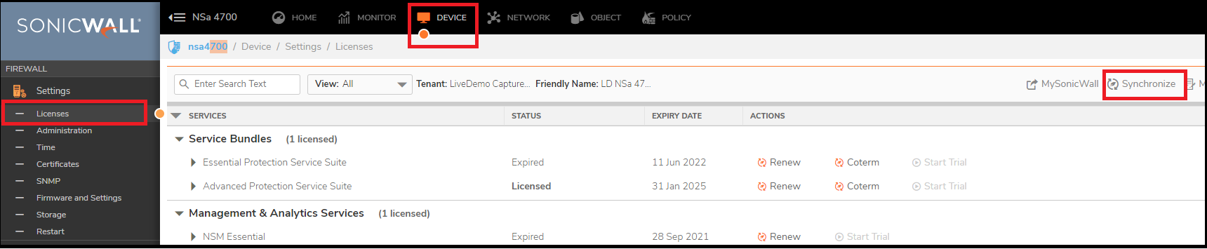
 TIP: If the DNS servers are not resolving, try changing the DNS IP addresses on the SonicWall WAN Interface and then try to synchronize the licenses.
 NOTE: The SonicOS Enhanced license is not shareable between the primary and the backup appliances. Both appliances must be licensed separately.
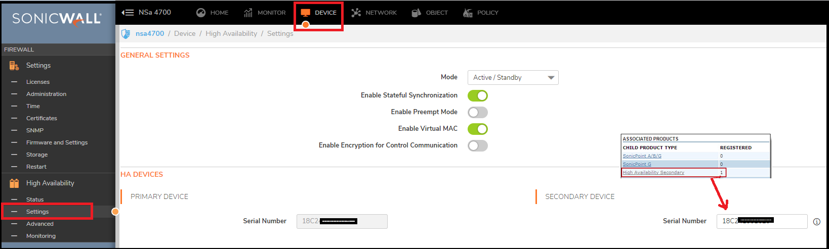
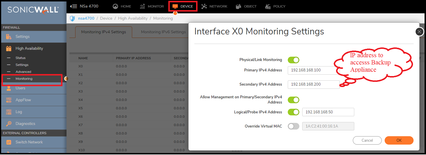
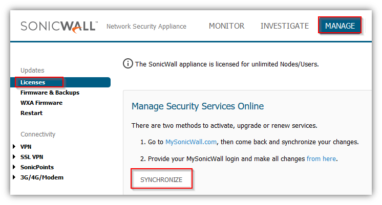
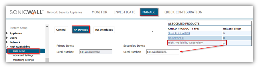
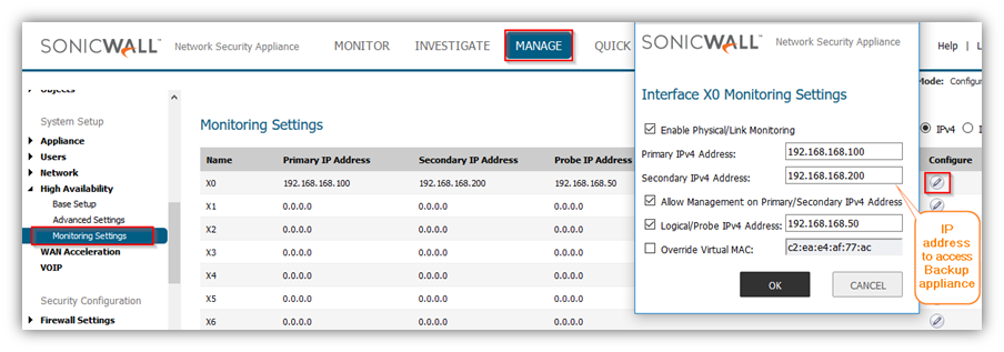
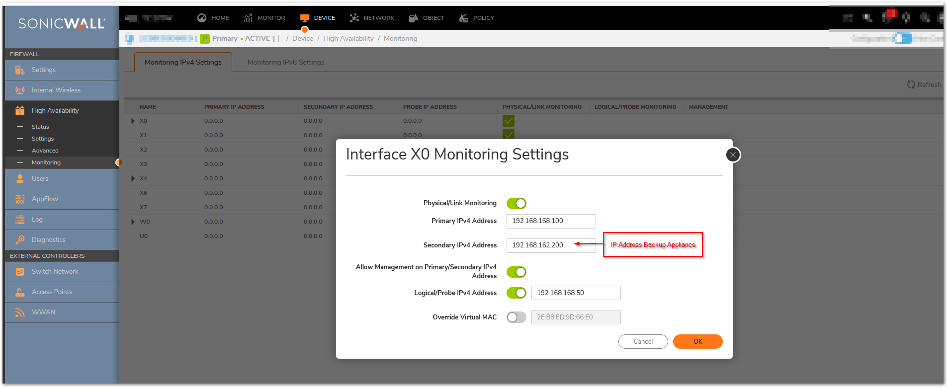
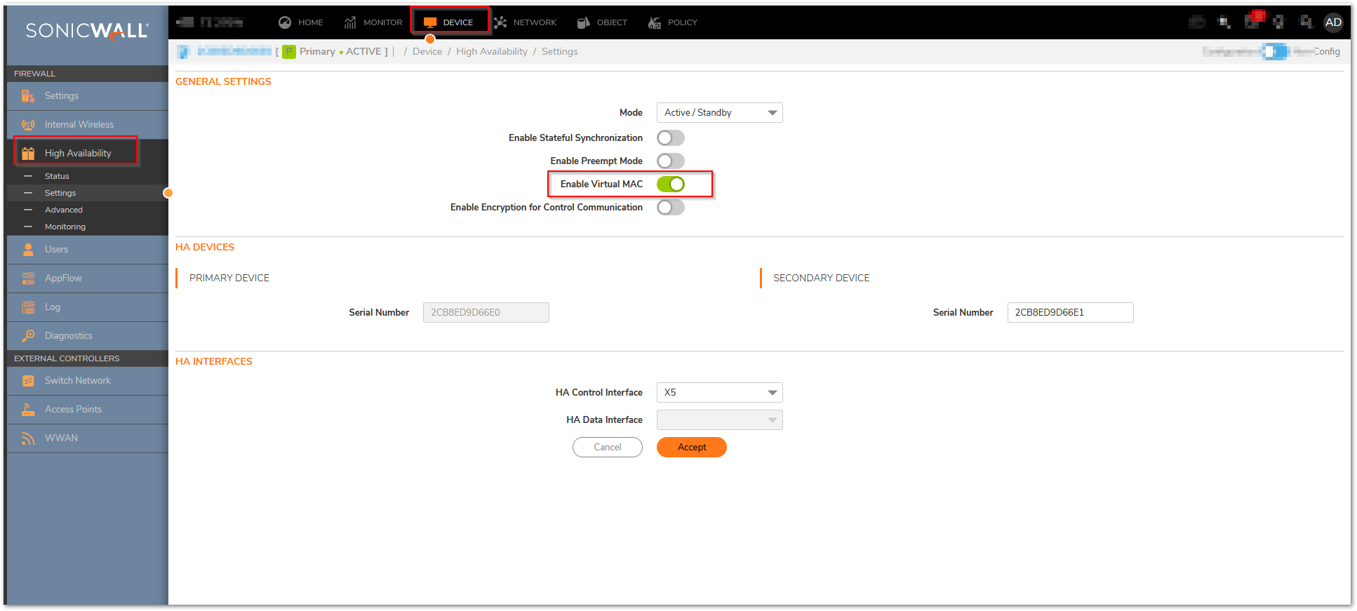
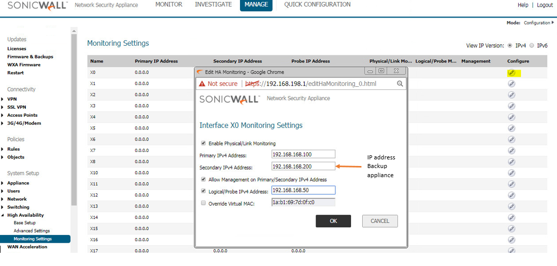

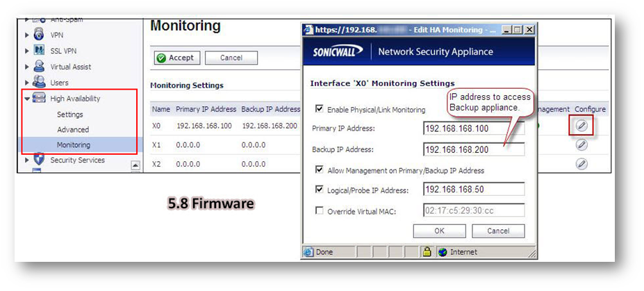
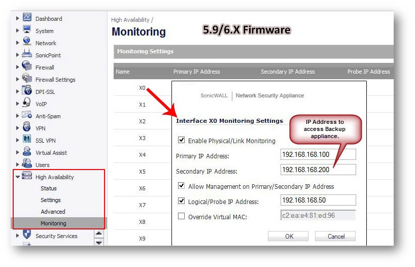
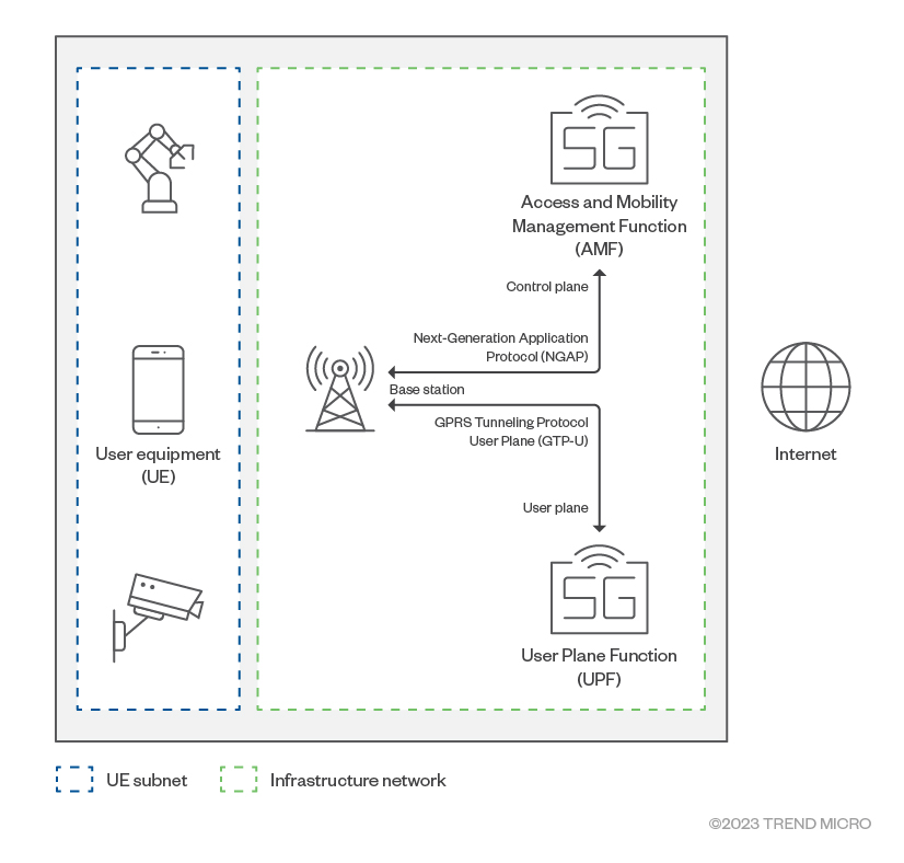
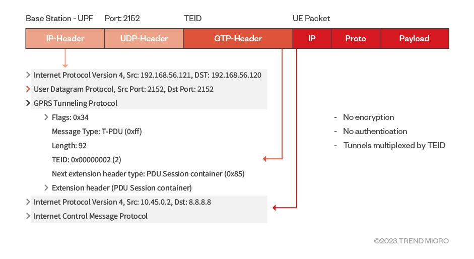
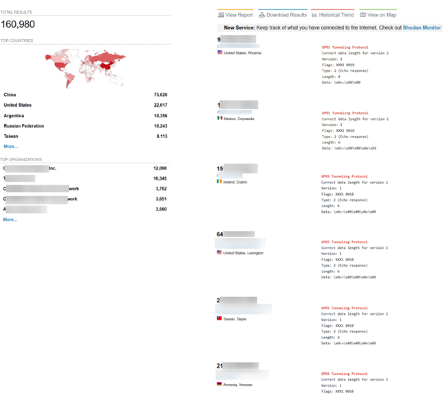
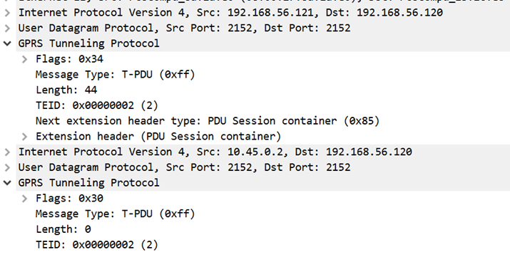
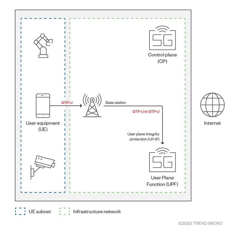
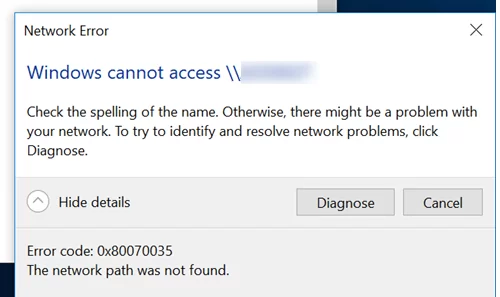
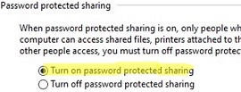
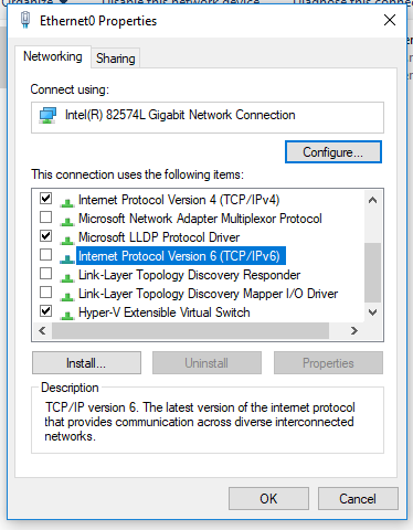
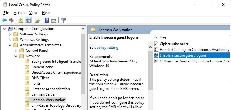
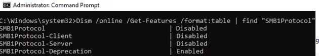
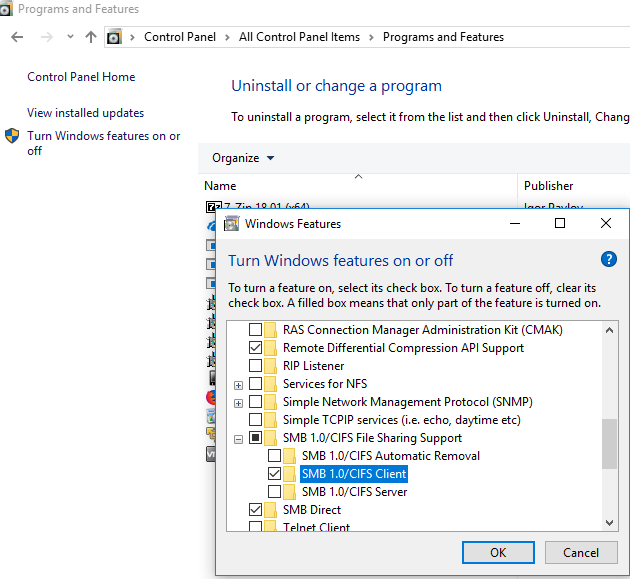
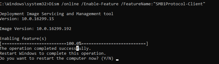
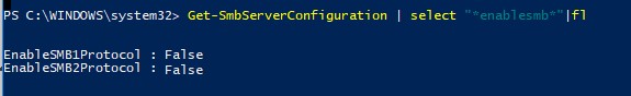
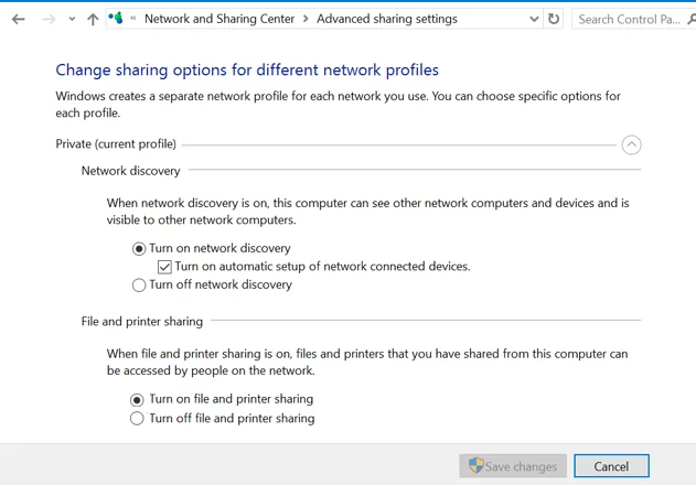
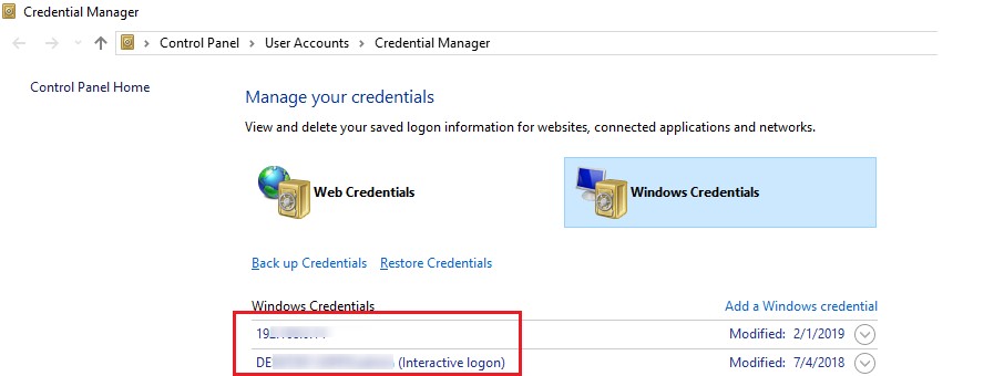
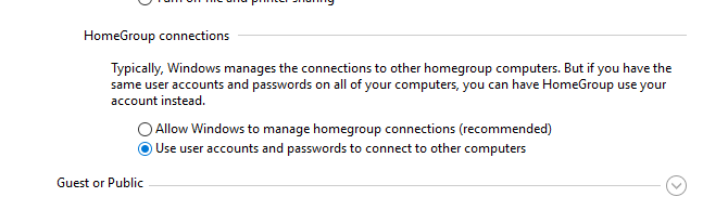
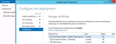
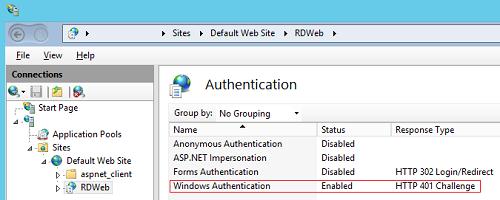
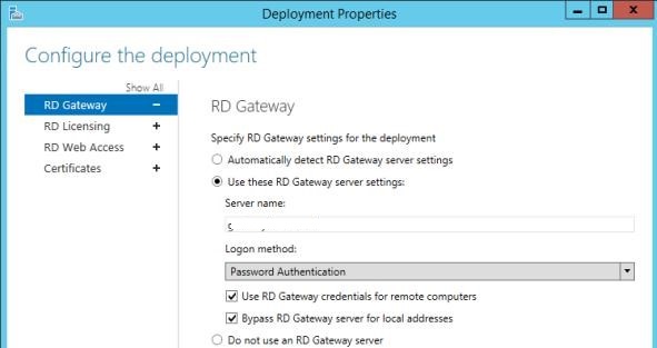
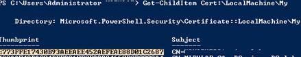
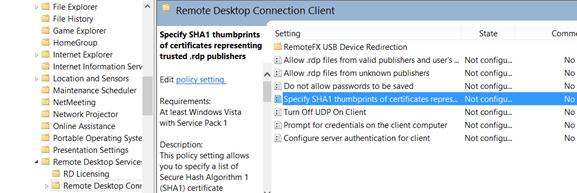
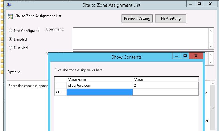
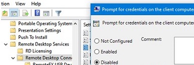
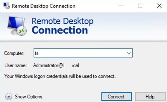
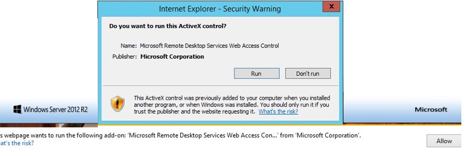
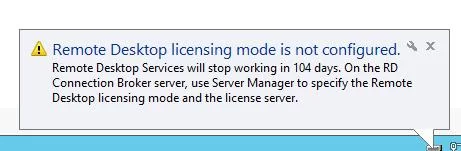
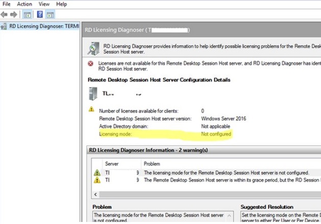
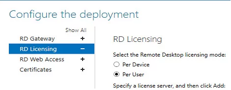
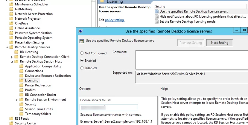
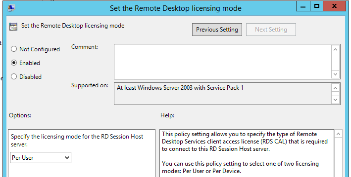
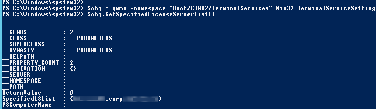
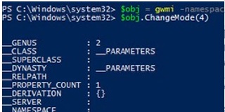
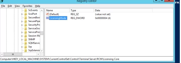
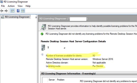
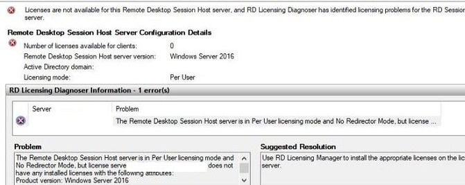

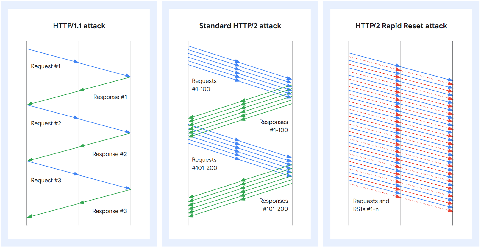
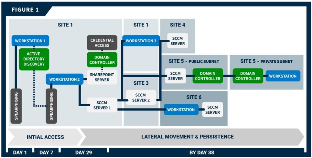
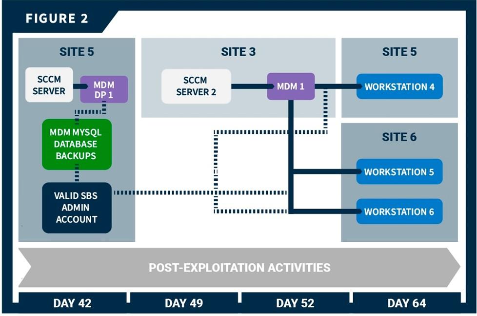
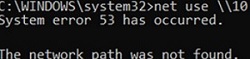
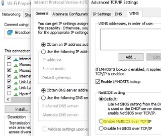
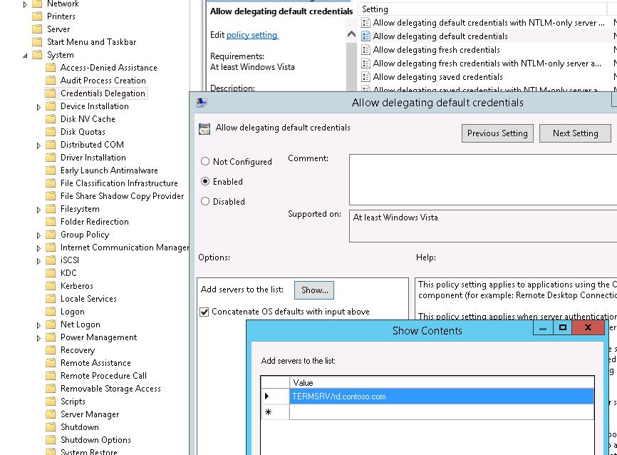
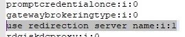
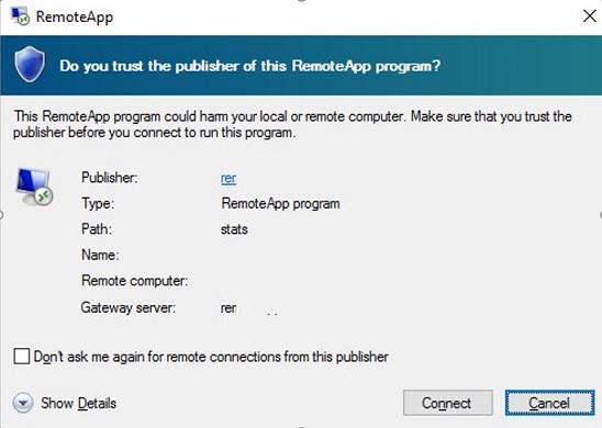
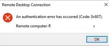