If you’re an admin of an account, then you should probably stop using admin as your username. It turns out that this is one of 3 big security mistakes that users make when it comes to WordPress security. In today’s post, we’ll go over why admin usernames are not a good idea and the best practices for choosing a new username in order to keep your site safe from hackers!
Why is choosing the admin username bad for my WordPress website’s security?
If you are the admin of an account, then you might think that using admin as your username is a great idea. However, this isn’t exactly true! When it comes to security on WordPress websites and choosing usernames for admin accounts, there are quite a few things that can go wrong if you use admin as your username.
The first reason why having the admin username is bad for security purposes has to do with brute force attacks. Brute force attacks are when hackers try different combinations in order to gain access to passwords or private information about users on any given website. Because so many people choose admin as their password due to its simple structure (admin), these kinds of hacker attacks tend to be very successful because they essentially have everything they need to gain access to a site right from the start.
In addition to being vulnerable to brute force attacks, admin usernames are also very susceptible to social engineering scams. Social engineering scams are when hackers try to get unsuspecting users to give away personal information like passwords or log-in credentials by posing as someone that the user trusts. For example, if you receive an email from your bank asking for updated login information, and you’re not sure whether the email is legitimate or not, it’s best to call customer service and ask them about the message before taking any further action.
Since admin is such an easily guessed username, it makes it much easier for scammers to try and scam people into giving away their personal log-in details. So, if you’re using admin as your username, it’s not only bad for security reasons but also makes you more susceptible to scams.
Tips For Choosing A Secure Username
If you want to be extra careful with how you choose usernames moving forward, there are two things that we would recommend doing. The first thing is to check if any other accounts have been made on your website or blog with similar names (e.g., administrator, support, helpdesk ). If you find any, change them to something more unique, like a special term, a department name, a person’s name. That way, even if someone tries to hack into your account, they’ll be met with a login error.
The second thing you can do is use a password manager to create and store strong passwords for all of your accounts (including admin ). This will help make sure that no one ever gains access to your site by guessing or cracking your password. If you’re not familiar with password managers, I’d recommend checking out LastPass or Dashlane. They both offer free and paid versions, so you can choose the one that’s best for you.
What are some safer alternatives to using admin as my WordPress website username?
If you’re looking for a more secure alternative to the admin username, then there are quite a few options that you can choose from. Here are some of our favorites:
– Username: YourFirstName + YourLastName – This is a great option because it’s unique and easy to remember.
– Username: CompanyName_UserName – This is another good option if you want to use your company name as your login credentials.
– Username: Password123! – This might not be the most secure option, but it’s definitely better than using admin as your username.
– Username: randomword123 – This is a good option if you want to create a unique username that isn’t easily guessed by hackers.
Whatever username you choose, be sure to make it something that you can remember and that isn’t easily guessed by hackers. And, most importantly, never use admin as your login credentials! Choosing a more secure alternative will help keep your WordPress website safe from unwanted intrusions.
The holidays are a time for sharing, giving, and family. However, cybersecurity experts warn that cybercriminals also take advantage of this special time to spread malicious software or steal credit card information. In order to reduce the risk of becoming a victim during the holiday season, we’ve compiled cybersecurity tips you can follow to stay safe online.
P.S. This is not just any blog post on cybersecurity; it’s our top 10 list!
Tip #1: Be Cautious of Phishing Emails
One of the most common ways cyber criminals attempt to steal your personal information is by sending phishing emails. These emails often look like they’re from a legitimate company or organization, but in reality, they’re from cybercriminals trying to trick you into giving up your personal information. To protect yourself, be cautious of any email that asks for sensitive information such as your credit card number or password, and never click on links or open attachments in suspicious emails.
Tip #2: Use Strong Passwords
Another way cybercriminals can gain access to your personal information is by stealing your passwords. In order to protect yourself, use strong passwords that are difficult to guess. You can create strong passwords by using a combination of letters, numbers, and symbols. Also, be sure to never use the same password for multiple accounts.
Tip #3: Keep Your Devices Protected
One of the best ways to protect your devices from cybercriminals is by keeping them protected with antivirus software. Antivirus software can help protect your devices from malware and other types of malicious software. In addition, it’s important to keep your operating system and applications up-to-date as this can also help protect you from cybersecurity threats.
Tip #4: Be Cautious When Using Public Wi-Fi Networks
Public Wi-Fi networks are a convenient way to stay connected when you’re out and about, but they can also be a hotspot for cybercriminals. These networks are often unsecured, which means your data is vulnerable to being stolen by hackers. To protect yourself when using public Wi-Fi networks, make sure you use a VPN and be careful not to enter any sensitive information such as your credit card number or passwords.
Tip #5: Avoid Shopping Online on Unsecured Websites
When shopping online, it’s important to only visit websites that are secure. Secure websites have a web address that starts with “HTTPS” instead of “HTTP” and they will usually have a lock symbol next to their web address. Cybercriminals often create fraudulent websites that look identical to secure websites in order to trick you into entering your personal information. When shopping online, always make sure the website is secure before entering any sensitive information.
Tip #6: Use a Password Manager App
Using strong passwords can be difficult when trying to remember them all. To help protect yourself, use password manager apps that are designed for this purpose. These apps create complex and unique passwords for every account on your devices so you don’t have to worry about it! Plus they automatically log you in with these saved passwords whenever needed, making it even easier too!
Tip #7: Turn On Two-Factor Authentication Whenever Possible
Two-factor authentication provides an extra layer of security by requiring two different forms of authentication before you can log in to your account. This could be something as simple as a code sent to your phone or a one-time password that is generated by an app. By turning on two-factor authentication, you can help protect yourself from cybercriminals who may try to steal your login credentials.
Tip #8: Check Your Credit Report Regularly
One way to help protect yourself from identity theft is by checking your credit report regularly. You can get a free copy of your credit report once a year from each of the three major credit reporting agencies. Checking your credit report can help you identify any suspicious activity and take action if necessary.
Tip #9: Be Wary of Social Media Scams
Social media scams are a common way for cybercriminals to steal your personal information. These scams often involve fake posts or messages from friends asking you to click on links or download files. Always be wary of any posts or messages that seem suspicious and never click on any links or download any files without verifying the source first.
Tip #10: Back Up Your Data
One of the best ways to protect your data from being lost or stolen is by backing it up regularly. By backing up your data, you can ensure that if your device is ever lost or stolen, you will still have a copy of all your important files. There are many different ways to back up your data, so find one that works best for you and stick with it!
These are just a few of the many cybersecurity tips that you can use to help protect yourself during the holiday season. Even though there are real risks out there, we wish you all the best during this festive time! Stay safe and enjoy your time with family and friends! 🙂
DNS tunneling is a technique that encodes data of other programs and protocols in DNS queries, including data payloads that can be used to control a remote server and applications. Because of this, DNS tunneling – and DNS exfiltration associated with it by threat actors – is of great concern to many IT and SecOps teams. Fortunately, new developments in the Cisco Umbrella DNS cache system allow for faster and more reliable detection of DNS tunneling and exfiltration events.
How Does DNS Tunneling Work?
DNS tunneling revolves around the transfer of data. So, if we have:
Input Data data – Name: Alice, Age: 25, SSN: 123-45-678
Using DNS exfiltration, we can encode and send this data placed in several subdomains of the domain under our control as a single entry:
Or, we can use multiple entries using multiple queries to large numbers of domains:
jzqw2.zj2if.my.tunnel.com
wgsy3.ffraw.my.tunnel.com
ozj2g.i2syu.my.tunnel.com
2tjy5.dcmrt.my.tunnel.com
Users can abuse this technique – as seen in Fig. 1 below – by installing a free DNS tunneling tool to bypass IT policies and/or monitoring. They can also use this technique to bypass network authorization to obtain free internet access in hotels and airports.
Fig. 1
Attackers can use outbound DNS requests to send encoded exfiltrated data to their infrastructure – as seen in Fig. 2 below – or use DNS responses to send commands to compromised systems and manage infected devices remotely.
Fig. 2
Improvements to DNS Tunneling Realtime Detection
Today, we’re thrilled to announce that organizations have a powerful new ally to protect against data exfiltration and unauthorized DNS tunnels in their networks. Cisco Umbrella has developed a new proprietary cache within our DNS resolvers to work alongside our machine learning modules. Our newest machine learning module is tuned to detect data exfiltration and DNS tunneling events.
This new module monitors DNS traffic for behavioral patterns and traffic exfiltrating data, efficiently building enough information to detect and block data exfiltration. And, in the event circumstances and domain reputations change, this module will correct itself and let traffic through.
We made this update because, over the past couple of years, we’ve seen organizations more productive and more connected amidst the new reality of working digitally during the pandemic. The explosion of logins and bandwidth, though, has at times come with reductions in digital security. Data exfiltration has become a new reality, and one hole attackers punch is in the DNS.
Powering Improvements With a Revolutionary DNS Cache
The technology stack powering Cisco Umbrella’s DNS resolvers handles blistering loads of DNS traffic from ISPs, global organizations, municipalities, schools, and homes. Building on this, we’ve hacked the heart of the DNS resolver – the cache. And while we dig into the details of this new functionality in our DNS tunneling solution brief, we also want to provide you with an overview here.
The cache of a DNS resolver enables serving the swell of global traffic without fault, outage, and ease. It also insulates the backbone of the internet from being overwhelmed with identical queries. Caches store data locally so that it can be served quicker.
Tunneling Cache
The tunneling cache enables us to glue together a sequence of queries that are otherwise distinct atomic events. With proprietary key and data fields, we seamlessly incorporate rapid cache updates unbeknownst to web surfers. We maintain lightning speed throughout by merging incoming data fields using tricks found in probabilistic algorithms. Gluing together each individual’s DNS queries provides access to a rich amount of information, otherwise hidden. Organizations can now get personalized DNS tunneling monitoring, detection, and enforcement in real time.
Encryption Payloads
We pair the new DNS cache with a lexical engine highly trained at identifying encrypted messages. Our researchers dug into various encryption protocols and created a stateful algorithm capable of churning through every character transition in a domain name and identifying encryption payloads with high fidelity.
Take DNS-Layer Security to the Next Level
Cisco Umbrella analyzes internet activity to uncover known and emergent threats in order to protect users anywhere they go. Together, these capabilities power Umbrella to predict and prevent DNS tunneling attacks before they happen. Enabling this security category reduces the risk of DNS tunneling and potential data loss. Organizations can choose to block users from using DNS tunneling VPN services, or they can monitor the results in reports, providing flexibility to determine what is suitable given their risk tolerance.
Address your DNS blind spot by enforcing security over port 53 both on and off the corporate network. Request a personalized demo of Cisco Umbrella today to explore how this exciting new feature can help protect your enterprise.
Last year threw a lot at cybersecurity teams, from the emergence of several high-profile cyberattacks to the revelation of widespread vulnerabilities. As we all move into 2022, odds are your team is re-thinking your cybersecurity strategy to help make your organization more resilient and flexible. This should involve an evaluation of your cybersecurity solutions, as they impact the implementation and effectiveness of any strategies your team creates.
In our ebook 7 ways to strengthen your security in 2022 and beyond, we discuss the different ways you can amplify and extend your cybersecurity stack this year using Cisco Umbrella. But if you’re looking for some tips to get you started, here are three things to keep in mind as you plot out your cybersecurity strategy:
1. Make Sure Your Cybersecurity Solutions Don’t Impact Network Speeds
The use of internet resources and cloud services was on the rise before the COVID-19 pandemic. Now that employees have spread out – collaborating with coworkers and performing business-critical tasks from anywhere they have internet access – cloud-based tools have become more critical than ever.
This means that an effective cybersecurity strategy needs to balance the implementation of strong protections against the need for minimal latency on the company network. From a business perspective, cyber safety can’t come at the expense of speed.
In order to maintain this balance, take a look at your cybersecurity solutions and evaluate the following:
Routing Algorithms – Frequently, having fast and secure internet access comes down to a cybersecurity vendor’s data center network and routing algorithms. Make sure your cybersecurity solutions come backed by a robust global data center network and transparent routing protocols with automated failover to the fastest available servers. This minimizes latency, regardless of where users on your network are located.
Peering Relationships – Peering relationships allow cybersecurity vendors to minimize latency without compromising on security. As you reevaluate your cybersecurity strategy in the coming year, make sure your vendors have peering relationships with large cloud service providers your organization relies on. This allows employees to easily access the tools they need without introducing added latency.
Keeping network speeds in mind while you refine your cybersecurity strategy for the upcoming year can improve employee satisfaction, affect executive buy-in, and have an impact on your organization’s bottom line.
2. Strengthen Cybersecurity Infrastructure to Reduce Disruptions
Last year, we all experienced more than our fair share of network disruptions, outages, and downtime. Several of these events were impactful enough to make it into the news cycle. And while an outage isn’t the same thing as a cyberattack, your cybersecurity strategy should include finding solutions that are designed to reduce downtime instead of causing it.
Take some time to review the track record of your vendors. For example, do they have a proven record of resiliency and uptime? Better yet, can they handle infrastructure disruptions without passing those disruptions onto your users? For example, the unique DNS logging features included in Cisco Umbrella DNS-layer security can be used during certain events – like the 2021 Akamai outage – to keep users connected to business-critical cloud tools despite provider outages.
3. Make Sure Your Cybersecurity Strategy Includes Guest WiFi Considerations
Between the move to a hybrid work model and the gradual reopening of public spaces, odds are you’ll find more employees and clients using your guest WiFi in the coming year. So, it’s essential to make sure that both your private and guest WiFi networks have the speed users desire and the protection you need.
Does your suite of cybersecurity solutions provide your team with the ability to filter content and enforce security protocols over your guest WiFi network? Does your security stack allow you to maintain a single IP address for your entire enterprise, streamlining the management of guest WiFi security policies? Finally, can your cybersecurity solutions handle the uptick in user traffic that guest WiFi causes without increasing latency? If the answer to any of these questions is “no,” it may be time to think about adjusting your security stack.
Looking for More Ways to Strengthen Your Cybersecurity Strategy?
Outlook for Microsoft 365 Outlook for Microsoft 365 for Mac Microsoft 365 for home More…
Most email apps like Outlook are able to automatically configure email server settings. If you need server settings or help finding your server settings, click on one of the links below:
If you’re connecting to an Exchange mailbox and not using Microsoft 365 email, or if you aren’t sure if you’re using Microsoft 365 email, do the following to look up your settings:
In Outlook Web App, on the toolbar, select Settings > Mail > POP and IMAP.
The POP3, IMAP4, and SMTP server name and other settings you may need to enter are listed on the POP and IMAP settings page.
What server settings do I need from my email provider?
To help you get the info you need, we’ve put together a handy chart of the email server settings you should ask for. You will most likely have to set up your email as an IMAP or POP account as well. What are POP and IMAP? Check with your provider if you’re not sure which to use.
Note: When you use an IMAP or POP account, only your email will sync to your device. Any calendar or contacts associated with that account will be stored only on your local computer.
Follow these instructions to get your email settings:
Print out this page and keep it within reach.
Call your email provider and ask them about the settings in the chart below.
Write down the corresponding email server settings in the empty column.
Return to your email app and enter the information to complete your email setup.
Note: You may only need some of the settings on this list. Find out from your email provider what you will need to access your email on your mobile device.
General Email Settings
Setting
Description
Write Your Setting Here
Example
Email Address
The email address you want to set up.
yourname@contoso.com
Password
The password associated with your email account.
——–
Display Name
The name you want your email recipients to see.
Mike Rosoft
Description
Add a description of your email account.
Personal, work, etc.
Incoming Mail Server Settings
These settings are for sending email to your email provider’s mail server.
Setting
Description
Write Your Setting Here
Example
Host Name
Your incoming mail server name.
outlook.office365.com
Username
The email address you want to set up.
yourname@contoso.com
Port
The port number your incoming mail server uses.
Most use 143 or 993 for IMAP, or 110 or 995 for POP.
Server or Domain
This is your email provider.
yourprovider.com, gmail.com, etc.
SSL?
Is your email encrypted using SSL?(SSL is enabled by default in the Outlook mobile app)
SSL Enabled
Outgoing Mail Server Settings (SMTP)
These settings are for sending email to your email provider’s mail server.
Setting
Description
Write Your Setting Here
Example
SMTP Host Name
Outgoing mail server name. Most often smtp.yourprovider.com
smtp.office365.com
SMTP Username
The email address you want to set up.
yourname@contoso.com
SMTP Password
The password associated with your email account.
——–
SSL?
Is your email encrypted using SSL?(SSL is enabled by default in the Outlook mobile app)
If you have a work or school account that uses Microsoft 365 for business or Exchange-based accounts, talk to your Microsoft 365 admin or technical support.
If you value your security and privacy, then a VPN is an absolute necessity. A VPN, or virtual private network, stops others (even your internet service provider) from snooping on your online activity by routing all your internet traffic through a secure, encrypted tunnel. VPNs work especially well for guaranteeing that you’re protected even when using unsecured public Wi-Fi networks, too.
And nowadays, with all of us using our mobile devices more than ever before to get online, it is essential that our cell phones are equipped with a VPN so we can be fully protected on the go.
How can I set up a VPN on my iPhone?
There are two ways to accomplish this. The first method — and the one that will be most suitable for the majority of people — is to choose a VPN provider and then download and install its app from the Apple App Store. In general, the process will be super easy and the installer will guide you through any settings that you may need to configure.
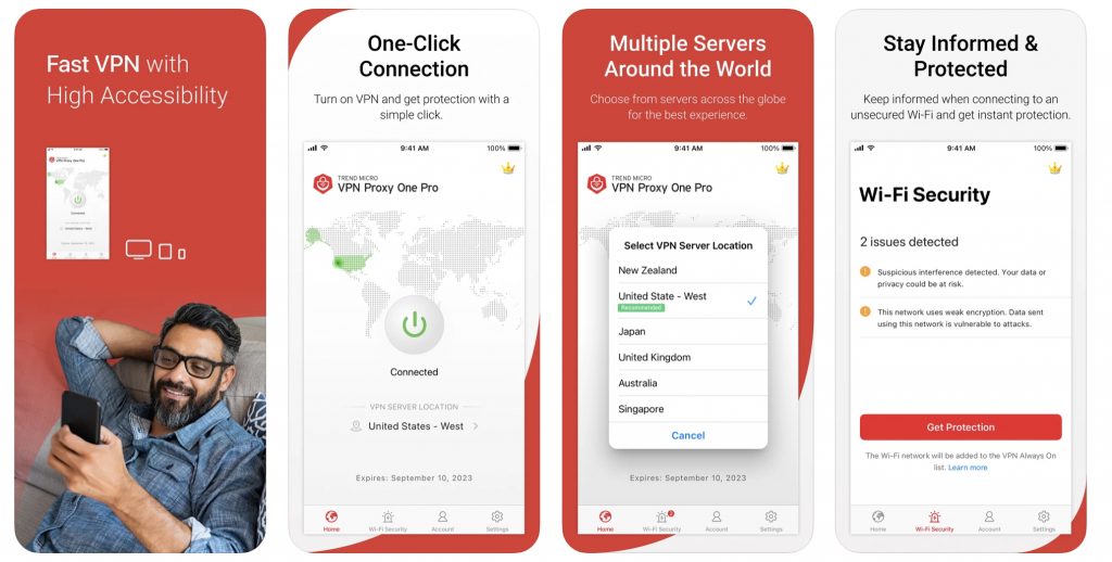
Take VPN Proxy One Pro for example. The setup process simply couldn’t be any easier. Within minutes of downloading the app from the App Store (click here to do this, by the way), your iPhone will be protected by world-leading encryption and you’ll be free to connect to the internet safely, even on public Wi-Fi networks.
The second method, which is outlined below, is only recommended for those who are a little more tech-savvy. This option is perfect for people who want more control over their VPN experience and don’t mind putting in the extra time and effort to get it. This method allows you to choose which protocol you use as well as customize other settings, but it does require some additional knowledge.
But before we explain the second method, we need to quickly talk about VPN protocols…
What are the VPN protocols natively supported by iOS?
Before you can manually set up a VPN on your iPhone, you’ll need to select which VPN protocol you wish to use. Here are the ones that natively work with iOS:
L2TP
L2TP (Layer 2 Tunneling Protocol) is a type of tunneling protocol. Because L2TP does not offer any encryption on its own, it is normally paired with IPSec (see below). The two technologies form an excellent partnership and together provide great security. It is not as fast as some other options, however.
IKEv2
Just like L2TP, IKEv2 (Internet Key Exchange version 2) also doesn’t offer any encryption of its own, so must also be paired with IPSec. It is faster than L2TP and works particularly well with mobile devices because it can easily move between connection types (Wi-Fi to a cellular network, for example). Although it was jointly developed by Microsoft and Cisco, it is still natively supported by iOS.
IPSec
IPSec (Internet Protocol Security) is also natively supported by iOS and can be used on its own as a VPN protocol.
How to manually set up a VPN on iPhone
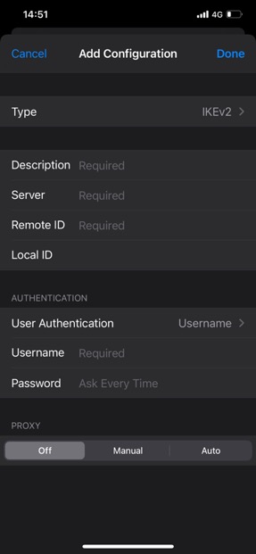
Once you’ve decided on which protocol to use, to manually configure a VPN on iOS, go to Settings > General > VPN > Add VPN Configuration > Type. From here, you can select either IKEv2, IPSec, or L2TP (which actually comes with IPSec, even though it isn’t made clear).
After selecting the VPN protocol type, you will need to fill out the other details. Most of the additional information should be available on the VPN provider’s website, either in your account settings or in the online documentation, but if you are unsure of where to find anything, it is best to contact them directly.
Once you’ve filled in all the required information, click Done in the right-hand corner and you’re good to go!
Stay connected, stay secure
If you, like most of us, rely on your mobile device to stay connected, then the value that a VPN offers simply cannot be understated. With everyone using their mobile devices for so much these days — email, social media, online shopping, etc. —when it comes to protecting our sensitive data and safeguarding our privacy, VPNs are effectively essential.
Regardless of how you go about setting up your VPN on your iPhone — whether you choose to just quickly download and install the app or configure each of the settings individually, VPN Proxy One Pro is a truly excellent choice. Click the button below to read more about it.
Blue and White status LEDs apply to all our UniFi access points, routers, switches and the UDM (base model) with the exception of the legacy devices: UAP, UAP-LR, UAP-Outdoor5.
Legacy UAPs have Amber and Green LED on the front of the unit. See this section for legacy AP LED patterns.
The animations are for illustrative purposes – the speed of the flashing or strobing patterns below might differ slightly with that of the device.
While the LED patterns below are shown for Access Points, the rest of the UniFi device LED patterns have the same meaning.
Flashing White / Off every 1/2s
The device is initializing and booting up
Steady White
The device is awaiting Adoption
Slow flashing Blue (UDM only)
A client device is connected to the UDM via Bluetooth
Steady Blue
The device is adopted and is in normal operating mode
The device firmware is currently being upgraded – do not interrupt the process!
(UDM will flash only white during an upgrade)
Blue and flashing Off every 5s
Access Point has lost network connectivity and is searching for wireless uplink
Rapid flashing Blue / Off
The device “Locate” feature was activated in the UniFi Network application
Flashing White-Blue-Off
The device is in TFTP mode.
To enable this mode:
Hold the reset button before applying power
Continue to hold the reset button until this LED sequence appears
If this wasn’t intentional, please check if the device’s reset button isn’t jammed (it should click when pushed).
LED Off
The device is offline.
Verify the Power, POE, and Ethernet cables to troubleshoot.
UniFi Bridge to Bridge (UBB)
Aside from the statuses described above, the UBB has two additional ones:
Red with Circulating Blue LED
The 60 GHz link cannot be established or has dropped due to bad weather. If the UBB fails over to 5 GHz, the LED will remain red. When the 60 GHz link is re-established, the LED will turn blue or the custom color you selected in the UniFi Network application.
Note: If the other bridge device is within range and the UBB LED is red, we recommend adjusting the UBB’s position to enhance the signal strength.
Green
If the Alignment Tool enabled in the UniFi Network application, a green LED means the UBB devices are properly aligned.
Note: If the other bridge device is within range and the UBB LED is green and red, we recommend adjusting the UBB’s position until the LED is green.
Legacy Amber and Green LED patterns
Applies to: UAP, UAP-LR, UAP-Outdoor5.
Flashing Amber / Off every 1/2s: The AP is initializing and booting up
Steady Amber: The AP is awaiting adoption
Steady Green: The AP is adopted and is in normal operating mode (AP is broadcasting SSIDs)
Strobing Amber / Off: If this happens, power cycle the AP and reach out to our support team if it doesn’t change the LED pattern
Quickly flashing Amber / Green: The AP firmware is currently being upgraded – do not interrupt the process!
Green and flashing Off every 5s: AP has lost network connectivity and is searching for wireless uplink
Rapid flashing Green / Off: The device “Locate” feature was activated in the UniFi Network application
Flashing Amber-Green-Off: The device is in TFTP mode. To enable this mode, hold the reset button before applying the power and continue to hold it until this LED sequence appears. If this wasn’t intentional, please check if the device’s reset button isn’t jammed (it should click when pushed).
LED Off: The device is offline. Verify the Power, PoE, and Ethernet cables to troubleshoot.
LED patterns for ports
The ports of UniFi Security Gateways and UniFi Switches have a different type, number, and location.
Please make sure to reference your specific device model’s Quick Start Guide (QSG) for the exact location and description of its ports.
Console Port’s right LED (in the applicable devices):
LED Off: Power Off
LED Green: Power On
Speed/Link/Act (right LED ports other than Console):
LED Off: No Link
LED Amber: Link Established at 10/100 Mbps
LED Flashing Amber: Link Activity at 10/100 Mbps
LED Green: Link Established at 1000 Mbps
LED Flashing Green: Link Activity at 1000 Mbps
PoE (left LED on ports of applicable devices):
LED Off: No PoE
LED Amber: IEEE 802.3af/802.3at
LED Green: 24V Passive
SFP (in the applicable devices):
LED Off: No Link
LED Green: Link Established at 1 Gbps
LED Flashing Green: Link activity at 1 Gbps
See specific port LED information in the Hardware Overview section (between pages 5 and 6) of the Quick Start Guides (QSG). You can find the QSGs in the Documentation section of our UniFi Downloads page, by searching for the device in question in the left hand menu.
LED patterns for PoE Adapters
LED is Off: PoE is Off.
LED is On and steady: PoE is functioning as it should.
LED is blinking: this is not a configured state, this may indicate that the device is not connected properly, or that something is wrong with the cable.
How to disable device LEDs
The device status LEDs can be disabled for all the site, or only for specific UniFi devices.
To enable/disable status LEDs throughout a site, go to to Settings > Site on the UniFi Network application and edit the LED feature in the Services section.
To configure specific devices individually:
Go to the Devices section and click on the device you wish to edit to bring up the Properties panel
Go to Config > General > LED and switch the Site Settings to On or Off.
This article describes how to access the emergency recovery user interface (UI) and recover a UniFi Cloud Key or a UniFi Cloud Key Gen 2 (UCK-G2-PLUS and UCK-G2 models). From this recovery UI you can reset it to factory defaults, reboot it, power it off and upgrade the firmware.NOTES & REQUIREMENTS:
To upgrade the firmware, you will need to download a firmware file (.bin) for the Cloud Key found in our Downloads page. Use the left hand menu to select the correct Cloud Key model and find the newest firmware available.
To access this interface you will need to know the IP address of the Cloud Key (visible in the device screen).
For second generation Cloud Keys (UCK-G2 and UCK-G2-PLUS) follow these steps to access the Emergency Recovery UI:
Power off the system.
Press and hold the reset button and then power on the Cloud Key by connecting it to the power source.
Cloudkey G2:
CloudKey G2 Plus
Keep the reset button pressed for about 10 seconds, or until you see the recovery LED pattern in a loop (blue – off – white). The LCD screen on the front panel will also read “RECOVERY MODE.”
Once the LED is flashing in the recovery mode pattern, open your browser and type the IP address for the Cloud Key, visible on the device’s screen. The IP address comes from your DHCP server, if you can’t access DHCP, the fallback IP will work: 192.168.1.30. However, keep in mind that if your Cloud Key does have a IP address assigned by the DHCP server, the fallback IP will not work.
You should be taken to the Recovery Mode screen. From here you can reset, reboot, power off and most importantly you can upload an updated firmware bin file.
To update the firmware, go to the Downloads page, find the correct Cloud Key model on the left hand menu and then click on the download button, read and accept information, and then download the firmware file to your computer to upload in the Recovery Mode UI. Once it is uploaded you will have to reboot the Cloud Key to complete the firmware upgrade.
The LED will flash white while upgrading and then a steady white when it is ready.
Cloud Key Gen 1 Emergency Recovery
For first generation Cloud Keys follow these steps to access the Emergency Recovery UI:
Power off the system.
Press and hold the reset button and then power on the Cloud Key by connecting it to the power source.
Keep the reset button pressed for about 10 seconds, or until you see the recovery LED pattern in a loop (blue – off – white).
Once the LED is flashing in the recovery mode pattern, open your browser and type the IP address for the Cloud Key. The IP address comes from your DHCP server, if you can’t access DHCP, the fallback IP will work: 192.168.1.30. However, keep in mind that if your Cloud Key does have a IP address assigned by the DHCP server, the fallback IP will not work. If you are using a Gen 2 Cloud Key you will see its IP address on the device screen.User Tip: If you don’t know your Cloud Key’s IP address, you can use thearp -a SSH command or software such as nmap to find the IP address.
You should be taken to the Recovery Mode screen. From here you can reset, reboot, power off and most importantly you can upload an updated firmware bin file.
To update the firmware, go to the Downloads page, find the correct Cloud Key model on the left hand menu and then click on the download button, read and accept information, and then download the firmware file to your computer to upload in the Recovery Mode UI. Once it is uploaded you will have to reboot the Cloud Key to complete the firmware upgrade.
Once it is uploaded you will have to reboot the Cloud Key to complete the firmware upgrade.
The LED will flash white while upgrading and then a steady white when it is ready.
In this article, we’re going to look at Virtual Private Networks in Azure and how you can use them. As you may know, a Virtual Private Network or VPN is an encrypted tunnel over the Internet or other shared networks, for example, a telco provider network.
VPNs use different technologies to encrypt the traffic, the most common ones are IPSec and OpenVPN SSL.
VPNs can connect branches (“sites”), and/or clients devices to a corporate network. Branch and Site VPN connections are most called Site-to-Site or S2S VPNs and are generally permanently connected. User and Device VPN tunnels are called Point-to-Site or P2S VPNs and are normally initiated by the user or automatically by an application but are disconnected after they’re no longer in use.
In Azure, you can have and use both types of VPNs but depending on the solution of choice it can be a different setup.
Let us first explore the VPN Service and Device Options you have in Azure.
VPN Services and Devices
In Azure there are three different options to build VPNs:
Using Virtual Network Gateways
Using Azure Virtual WAN
Using Network Virtual Appliances
All of them are capable of both Point-to-Site and Site-to-Site connections but they have different infrastructures underneath each of them.
Virtual Network Gateway
Virtual Network Gateways are a classic approach, that many network architects are familiar with. You deploy one VPN Virtual Network Gateway Service within a Virtual Network. That service combines Point-to-Site and Site-to-Site Gateways and can be deployed in different sizes.
Here’s a list of different VPN Gateway SKUs:
VPN Gateway Generation
SKU
S2S/VNet-to-VNet Tunnels
P2S SSTP Connections
P2S IKEv2/OpenVPN Connections
Aggregate Throughput Benchmark
BGP
Zone-redundant
Generation1
Basic
Max. 10
Max. 128
Not Supported
100 Mbps
Not Supported
No
Generation1
VpnGw1
Max. 30*
Max. 128
Max. 250
650 Mbps
Supported
No
Generation1
VpnGw2
Max. 30*
Max. 128
Max. 500
1 Gbps
Supported
No
Generation1
VpnGw3
Max. 30*
Max. 128
Max. 1000
1.25 Gbps
Supported
No
Generation1
VpnGw1AZ
Max. 30*
Max. 128
Max. 250
650 Mbps
Supported
Yes
Generation1
VpnGw2AZ
Max. 30*
Max. 128
Max. 500
1 Gbps
Supported
Yes
Generation1
VpnGw3AZ
Max. 30*
Max. 128
Max. 1000
1.25 Gbps
Supported
Yes
Generation2
VpnGw2
Max. 30*
Max. 128
Max. 500
1.25 Gbps
Supported
No
Generation2
VpnGw3
Max. 30*
Max. 128
Max. 1000
2.5 Gbps
Supported
No
Generation2
VpnGw4
Max. 30*
Max. 128
Max. 5000
5 Gbps
Supported
No
Generation2
VpnGw5
Max. 30*
Max. 128
Max. 10000
10 Gbps
Supported
No
Generation2
VpnGw2AZ
Max. 30*
Max. 128
Max. 500
1.25 Gbps
Supported
Yes
Generation2
VpnGw3AZ
Max. 30*
Max. 128
Max. 1000
2.5 Gbps
Supported
Yes
Generation2
VpnGw4AZ
Max. 30*
Max. 128
Max. 5000
5 Gbps
Supported
Yes
Generation2
VpnGw5AZ
Max. 30*
Max. 128
Max. 10000
10 Gbps
Supported
Yes
As you can see, picking the right size depends on several factors, including the expected number of connected users/sites as well as your aggregate bandwidth internet connections.
Depending on the SKU, gateways are deployed with different sets of features. Normally Virtual Network Gateways are deployed in a pair, in an active/standby configuration without using Availability Zones in Azure. To use Availability Zones, you need to use a SKU with AZ at the end. If you want to switch from one SKU to another, that will require a 45-minute downtime. A switch from non-Availability Zone to Availability Zone will require a complete redeployment of the Virtual Network Gateway, which can take up to 2 hours.
Azure Virtual Network Gateway supports the following encryption standards for Site-to-Site tunnels.
If you want to use Point-to-Site it supports OpenVPN (SSL/TLS-based), Secure Sockets Tunneling Protocol (SSTP) or IKEv2 VPN, more information is available here:
Azure Virtual Network Gateways are a traditional and proven way to deploy VPN solutions Azure, but they are not as flexible as other solutions.
Virtual WAN
In comparison to Azure Virtual Network Gateways, Virtual WAN Gateways work differently. The first major difference is that Virtual WAN makes a distinction between Point-to-Site Gateways and Site-to-Site Gateways. While in Azure Virtual Network Gateways both Gateways are one service, in Virtual WAN you have different Gateways for each use case.
Another major difference is that Azure Virtual WAN Gateways are deployed in scale units. These units can be scaled up and down on-demand, without any service interruption.
Another great feature is, that Virtual WAN Network Gateways are always deployed as highly available as possible. These Gateways are deployed in Virtual Machine Scale Sets and are by default deployed in Availability Zones if the Azure Region supports them. If an Azure Region does not yet support Azure Availability Zones, the Virtual Network Gateways are deployed in Availability Sets and as soon as the region supports Availability Zones, the backend is updated automatically.
Azure Virtual WAN Site-to-Site Gateways supports the following IPSec encryption standards.
You can have up to 200 Scale units supporting 100,000 clients. The payment model for Virtual WAN Point-to-Site Clients is by connected users per minute. So, it’s completely paid as you go per connected user plus the amount of Gateway Scale Units.
With Virtual WAN, there is another very important point, routing between Site-to-Site VPN, Point-to-Site VPN and ExpressRoute Gateways is enabled by default without any additional efforts by the customer. You can get more details via the link below.
Network Virtual Appliances are Virtual Machines running in a classical Virtual Network or Azure Virtual WAN. Those Appliances are third party and are available via the Microsoft Azure Marketplace.
Those appliances are harder to integrate and make highly available. The configuration is completely the responsibility of the customer, but for certain scenarios, they can offer major benefits for customers. One major selling point is if your organization has already standardized on a particular vendor/appliance, using the same one in Azure will ensure consistency and lower the learning curve for your network engineers.
Those appliances are mostly supporting additional features like Quality of Service, special encryption protocols or VPN Client tunnel optimization. For example, Barracuda Networks uses its own VPN Tunnel and encryption protocol TINA between their appliances and devices.
Then there are appliance partners who offer great VPN clients with additional features like filtering, split tunnelling by service or traffic optimization. Examples are Palo Alto Global Protect or FortiGate FortiClient.
Those appliances are much harder to integrate into a classic hub and spoke environment, with Virtual WAN the process of deployment is more automated. If you use those NVAs, you also have additional license costs for the appliances, which must be paid to the OEM.
As already mentioned, feature sets of those Network Virtual Appliances are often much richer than with bare Azure Virtual Network Gateways and Virtual WAN Gateways.
How to Deploy a VPN
Let me guide you on how to deploy a VPN Tunnel with the different service offerings. As the nature of the three solutions is completely different, I will split them up into three separate parts.
Virtual Network Gateway
As there is already a lot of deployment documentation out there, I will not create a new one. Let me just point you to the right resources, so that you can start and deploy according to Microsoft best practices.
As an additional option, you can pick a Network Virtual Appliance, if the Appliance of your choice is available in Virtual WAN. I would encourage you to make use of the more PaaS like the approach of Azure Virtual WAN.
The deployment of VPN Connections with Network Virtual Appliances is pretty diverse and depends on the vendor itself. Before I can point you to some example documentation, start with the documentation on how to deploy NVAs.
This documentation describes how to deploy an NVA in Azure.
You should follow that guide to ensure that the NVA is deployed according to supported standards. As there are a lot of partners out there, please contact the vendor of your choice to get additional guidance.
Palo Alto
The first vendor with very good documentation on the deployment is Palo Alto. You can find their guides below.
Barracuda is not that common among enterprise customers in Europe but offers a great portfolio of features including their own tunnelling protocol. Please find their docs below.
Within the Troubleshooting part, I will only concentrate on the troubleshooting guides for Azure Services, as the troubleshooting on NVA is extremely specific to the vendor.
For Azure Virtual Network Gateways, there are two good troubleshooting guides available in Microsoft’s Documentation.
One focuses on connections to Azure Virtual Network Gateways dropping or being unable to connect.
When looking into Azure Virtual WAN is more difficult, as you may not have access to the Monitoring and Troubleshooting logs. So, if you have the need for deeper troubleshooting, it makes sense to engage with Microsoft Support. In any case, you should have good monitoring in place according to documentation.
Sometimes Customers can confuse Azure VPN with other services available. Most commonly customers confuse Virtual Network Peering and Azure ExpressRoute with VPN Solutions.
Virtual Network Peering
Azure Virtual Network Peering is “only” a peering connection via the Microsoft Global Network between two Virtual Networks in Azure. It uses Software Defined Network technologies to connect the two networks and there is no Virtual Gateway necessary to do so. Virtual Network Peering is only used for interconnecting Virtual Networks within Azure and there is no option to use Virtual Network Peering to connect to the world outside of Microsoft Azure.
To learn more about peering, please visit the documentation below.
Microsoft Azure ExpressRoute is like VPN a connection to networks outside of the Microsoft Global Network. Its build to connect Customer Networks with the Microsoft PaaS Network via Peering or the Customer Private IaaS infrastructure using peering and private gateways.
The difference between Azure ExpressRoute and VPN is the fact that ExpressRoute is not leveraging internet connections or shared networks. With ExpressRoute you get a private end to end connection from your on-premises location to the Microsoft Global Network.
Those connections are more expensive but can offer more bandwidth or better Service Level Agreements, depending on your location and network service provider. ExpressRoute is not always better than VPN, always check your use case and your needs.
To be honest, Network Providers like to sell ExpressRoute due to better margins than with premium Internet connections. If you are interested in more information about that topic, you can visit some other articles here on the DOJO.
As is often the case with Microsoft’s service offerings there are several ways to achieve the same goal, here’s a flowchart I use when talking to customers about this.
That chart should help, at least for the initial discussion and understanding, which solution is best for your situation.
Conclusion
The “right” solution depends on what you want to achieve with your architecture. Often, it’s a decision driven by costs and features. Please also take complexity and maybe newer security requirements and approaches into account.
For example, if you’re searching for RADIUS integration, and the only solution might be costly, maybe it’s better to reconsider the requirement and check if you can achieve the same security requirements with Azure Active Directory Authentication instead.
The previous entries in this section have gone through the most complex sections of Failover Cluster Manager as it applies to Hyper-V. Most of the tool’s remaining functions deal with the supporting infrastructure for a cluster and are much less involved with the virtual machines. If you’re building up and configuring a brand new cluster, these areas are where you’ll spend a lot of your initial time. For a functioning cluster, they still contain useful information but won’t be frequently accessed.
How to Manage Hyper-V Cluster Nodes in Failover Cluster Manager
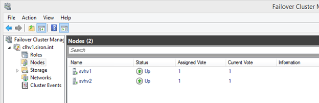
In the left pane underneath the cluster that you wish to work with, the second tree item is Nodes. This is where you’ll find the physical systems that perform the virtualization hosting for your cluster. If you have hosts that perform other roles for this cluster but are not cluster members, such as storage nodes, they should not appear here.
While it is technically possible for a single cluster to operate multiple roles, such as Hyper-V and Scale-Out File Server (SOFS), a single cluster cannot serve as both the storage platform and the virtualization platform for the same Hyper-V guests. Differing host types should be placed in separate clusters. The only secondary role supported in a Hyper-V cluster is the Hyper-V Replica Broker.
The typical node view should look something like the following. In this cluster, all nodes are present with a status of Up:
There are two context menus to work with in this section. As with all other aspects of Failover Cluster Manager, you can access an object’s context menu by either right-clicking it or by left-clicking it and looking in the panes at the far right.
For the Nodes tree object itself, there is only one unique item: Add Node. Clicking this will take you through the same screens that you saw in the first section of this application’s tour, except that the outcome will be the addition of a new node to an existing cluster rather than the creation of an all-new cluster. If you proceed through the wizard, you’ll be notified of the need to perform a cluster validation. Remember that you might need an up-to-date validation report if you contact Microsoft support.
The other items on the Roles tree node’s context menu are standard. You can customize the columns that appear in the center pane by selecting Customize, which is the only option in the View sub-tree. By default, you are shown the Assigned Vote and Current Vote columns, which give you the status of the cluster’s quorum. There is also an Information column that is usually empty, but will contain a preview of any error states. The last menu option allows you to Refresh the center pane to have Failover Cluster Manager re-check the status of the nodes. Finally, you can click Help to see Failover Cluster Manager’s MMC help window.
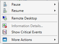
The context menu for a node is more complex, although not nearly to the same degree as what you saw for virtual machines in the Roles node.
Node Context Menu: Pause
Pausing a node makes it an ineligible target for role migrations. The node is still given a vote for quorum and remains in full communication with the other nodes. This is an ideal state if you wish to perform short-term manual maintenance operations on the node. This menu has two sub-menu items: Drain Roles and Do Not Drain Roles.
If you opt to perform a drain, the cluster will attempt to move all roles on that node to other nodes in the cluster based on its own balancing algorithms. Active guests with a priority of Medium or higher will be Live Migrated; all others will be Quick Migrated. Even if the drain operation is not fully successful, the node will be paused in order to prevent it from accepting any new roles.
Node Context Menu: Resume
The Resume option has the same options as the Pause menu in reverse: Fail Roles Back and Do Not Fail Roles Back. If you choose to perform failback, all roles that were migrated as part of the initial drain operation are retrieved after the node is resumed. Otherwise, they are left where they are.
Node Context Menu: Remote Desktop
This menu option starts the Remote Desktop Client, automatically targeted at the node.
Node Context Menu: Information Details
If any operation resulted in an error status, the Information column will show a short preview. Use this menu item to display the complete error message.
Node Context Menu: Show Critical Events
This menu item will spawn a minimalist event viewer window that shows critical events related to node and quorum management. Despite the implications in the context menu and the spawned window’s title bar text, the events are for all nodes.
Node Context Menu: More Actions
The More Actions menu gives you three sub-items. The first two are Stop Cluster Service and Start Cluster Service. In the current version of Failover Clustering, the outcome of stopping the cluster service in this fashion is very similar to the drain operation, with the exception that the cluster service (clussvc.exe) is gracefully halted. All of the node’s roles are drained and it cannot receive any incoming roles. The node will retain its quorum vote, although Dynamic Quorum may choose to rescind it.
The Start Cluster Service option will not restore drained roles. It will start the service, reattach the node to the cluster, and, if necessary, restore its quorum vote.
The final option on the More Actions menu is Evict. This should only be used when a node is being decommissioned or has failed entirely. In earlier versions of Failover Clustering, evicting a node was a fairly common troubleshooting step. It should no longer be necessary in current versions. Evicting a node does cause configuration information to be lost, so, even if rejoined, pre-existing validation reports may become invalidated.
How to Manipulate Storage for Hyper-V in Failover Cluster Manager
The storage node of Failover Cluster Manager allows you to work with cluster-controlled storage. Hyper-V does work perfectly well with virtual machines that are placed on file servers running SMB (storage message block) protocol version 3 or later. Version 3 debuted with Windows Server 2012. These storage locations are not controlled by the cluster and cannot be managed through Failover Cluster Manager. It can only work with standard cluster disks and Cluster Shared Volumes.
The Storage node has two sub-nodes of its own: Disks and Pools. Pools are used with Scale-Out File Servers (SOFS). It is technically possible to run Hyper-V roles and SOFS on the same cluster, but the virtual machines cannot be placed on space used by the same cluster’s SOFS. In addition to being unsupported, the system will error if you attempt to create such a “loopback” configuration.
Disks
For a Hyper-V cluster, the Disks sub-node is typically of much greater use. The only situation in which it would not contain any information is if you are not using a disk witness for quorum and all guests are stored on SMB 3 storage. In order for this section to be of any use, you must have connected shared storage to every one of the nodes using common direct-attached storage through an external SCSI interface, an iSCSI link, or a fibre channel link.
Each shared storage location must be formatted with NTFS or ReFS. A disk to be used for quorum must be formatted with NTFS. The details of preparing storage are not part of this tour. Storage will be talked about in more detail in a later article, but you can find detailed guidance on how to connect storage to a Hyper-V system here. Making the connections on the nodes will not automatically make them available to the cluster. That can be done through this section of Failover Cluster Manager.
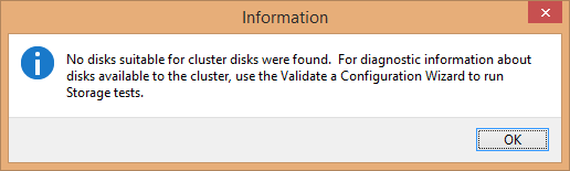
To begin, select the Disks node in the left pane and access its context menu. The very first item is Add Disk. If there is no unused storage connected to every node, you’ll receive a dialog indicating as much:
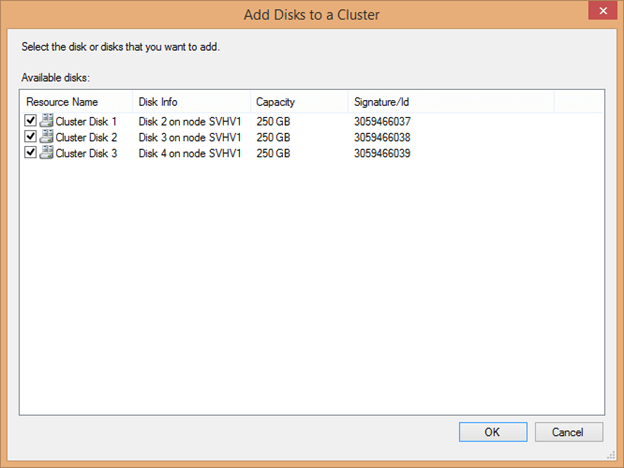
If one or more disks are available, you’ll see something like the following:
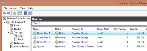
The cluster automatically determines the Resource Name by using the text “Cluster Disk” and incrementing a number. Disk Info helps you to identify what is being connected, as it does not read volume information such as labels. The signature can also be used to identify the disk; it’s retrievable by using Get-Disk. When adding several disks at once that are of equal size, be certain to match them when accessing this screen as it will not be so readily available after being attached to the cluster. Check the box(es) for the disk(s) you’d like to add and click OK. Each disk should then appear in the center pane:
The next item in the Disks sub-node’s context menu is Move Available Storage. Its sub-options are the same for virtual machine migrations: Best Possible Node and Select Node. These items operate only on standard cluster disks; quorum disks and Cluster Shared Volumes are unaffected. Every single cluster disk is moved if possible.
The remaining options in this node are the standard View, Refresh, and Help items which work as they do elsewhere in Failover Cluster Manager.
Disk Items Context Menu
The items in the center pane represent the disk-based storage assigned to the cluster. They have a dynamic context menu. Each item is presented below in alphabetical order.
Add to Cluster Shared Volumes: This option is only available for standard cluster disks. Once used, the disk is converted to a CSV. It no longer appears as a separate disk attached to a singular cluster node but becomes an entity underneath C:\ClusterStorage on all nodes. A folder named Volume# will be created to represent this disk. It can be renamed, but doing so after virtual machines are placed on it will cause those virtual machines to break. Any virtual machines that were on the cluster disk before it was converted will also be broken.
Bring Online: This returns an offline object to online status. All disk types are eligible.
Information Details: If the previous operation on this item in this console resulted in an error, this entry will become active. Clicking it will spawn a dialog with details about the error.
Move: The Move option is only available for Cluster Shared Volumes. It reassigns ownership to another node, either automatically with the sub-item Best Possible Node or by manual selection using Select Node.
More Actions: As with the menu it’s found in, this displays a dynamic menu with the following possible options:
Assign to another role: In a Hyper-V cluster, this menu item is not useful. You do have the ability to assign it directly to a virtual machine role, but that doesn’t grant any special abilities to the virtual machine that it doesn’t already have. Virtual machines can already use any cluster disk as a pass-through disk. Using this menu item could help visually reinforce that a particular virtual machine is using it as pass-through storage.
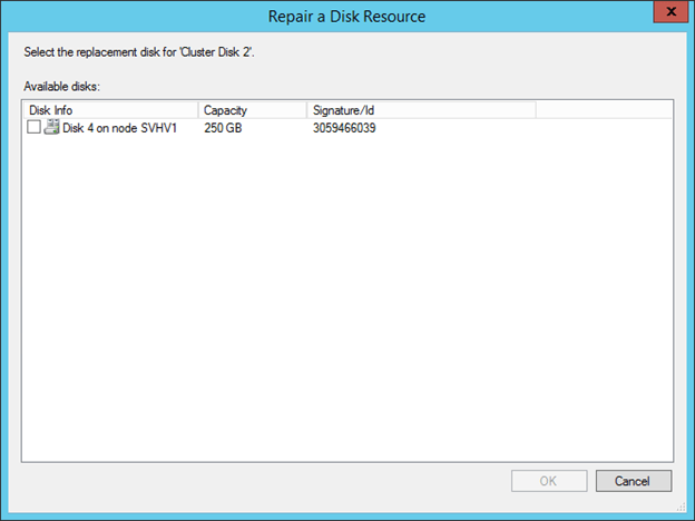
Repair: This item becomes active for a disk in an offline state. This menu item is to be used In the event that the disk is offline because it has permanently failed and you are replacing it. The replacement disk must be attached to storage but must not have been added as a cluster disk; if it was added, remove it. Upon clicking Repair, a dialog will appear with all available storage. Choose the item that will replace the failed disk. Upon selecting the replacement item, it will be added into the cluster with the name of the disk that was replaced. You will be prompted to bring it online to complete the repair.
Show Dependency Report: This item is of little use in a Hyper-V cluster as disk resources are not assigned directly to roles. For CSVs, it will display the underlying Cluster Disk resource.
Simulate Failure: Triggers the configured failure action for a standard cluster disk or the quorum disk.
Turn off Maintenance Mode: Restores a disk object that was previously placed in Maintenance Mode to normal operation.
Turn on Maintenance Mode: This mode removes protections against tools such as CHKDSK from running against the volume and disables the cluster’s automated health checks. When activated against a Cluster Shared Volume, you receive a warning that roles will be taken offline; this is not true for virtual machines. However, the volume’s representation under C:\ClusterStorage will disappear and virtual machines in that space cannot be Live Migrated until Maintenance Mode is ended.
Properties: A properties dialog will be displayed that will change depending upon the selected item. These will be explored after this list.
Remove: The selected standard cluster disk is removed from cluster disks. Virtual machines on it will instantly crash.
Remove from role: If a cluster disk is assigned to a role, a menu item will appear allowing you to return it to Available Storage.
Remove from Cluster Shared Volumes: The selected CSV is returned from CSV status to standard disk status. Any hosted virtual machines will instantly crash.
Show Critical Events: A minimal event viewer dialog is shown with any available critical events about the selected resource.
Take Offline: use this to take any disk resource offline. Any active virtual machines using this storage will instantly crash.
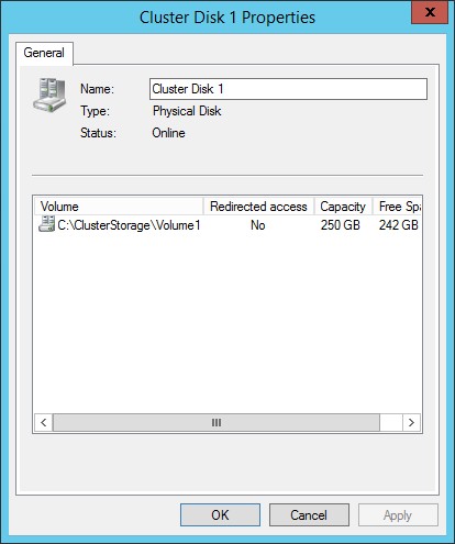
Properties Dialog for Cluster Shared Volumes
Of the three cluster disk types, the properties dialog for a CSV is the simplest:
The only modifiable control is the Name. This name is only used by Failover Cluster Manager and Failover Clustering. It does not change the way that virtual machines refer to their storage. You can change this at any time. The list box shows four sets of information. Volume is the logical path that the CSV is referred to on each node. This can be renamed using traditional file system commands and tools, but doing so after virtual machines are created on it will cause their links to break. Redirected Access indicates if the volume is in Redirected Access mode. Capacity shows the total space on the disk and Free Space displays how much of that space is unused.
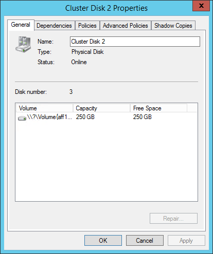
Properties Dialog for Standard Cluster Disks and Quorum Disks
The properties dialog is identical for the other two types. It contains a series of tabs. The first is the General tab and it looks very similar to the properties dialog for the CSV:
You can use this page to rename the cluster disk. As with a CSV, nothing is harmed by performing this operation. This dialog shows the cluster’s disk number, which can be referenced with the text-based tools and Disk Management. The center pane shows similar information to that of a CSV, although instead of a symbolic link path, the Volume is the drive letter, if one is assigned, or a raw volume identifier. Since cluster disks do not support Redirected Access mode, that column is not present.
The Dependencies tab will not show anything for the typical cluster disk in a Hyper-V environment since they are not commonly attached to roles. The Policies, and Advanced Polices tabs are identical in content and function to those for other cluster resources and were examined in the two preceding articles in this series.
The unique item on this dialog is the Shadow Copies tab. This setting is node independent and should be used instead of the traditional setting in Windows Explorer.
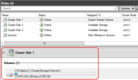
Details Pane
When a single cluster disk is selected in the center pane, that center pane will be divided into upper and lower sections. The lower section will show a quick summary of the item:
You can quickly see the space utilization for the volume and its drive letter or raw volume identifier (standard cluster disks and quorum disks) or its symbolic link (CSVs). In this pane, the item has a single-item context menu. A quorum or standard cluster disk will have the option to Change Drive Letter, which displays a very simple dialog allowing you to clear the drive letter or assign a new one from the available letters. A Cluster Shared Volume will give you the option to Turn On Redirected Access Mode if it is off or turn it on otherwise.
How to Manage Hyper-V-Related Cluster Networks in Failover Cluster Manager
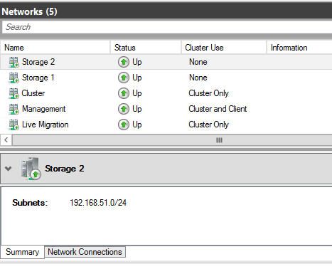
The next cluster tree item after Disks is Networks. This section gives access to the networking resources as managed by the cluster. Clicking this tree node will display all of the networks that the cluster is aware of in the center pane. By default, the cluster names them as Cluster Network 1, Cluster Network 2, etc.
The way that Failover Clustering identifies a network is by subnet. Every unique subnet discovered on each host will be displayed here. If a host has two or more adapters in the same subnet, only one of them will be displayed. If any host does not have an adapter in a subnet that can be found on other nodes, that network will be considered Partitioned. Configuring the subnets is a topic that’s tackled in the Networking article. As this is just a tour of the tool, it’s assumed that all of your subnets are already configured as desired.
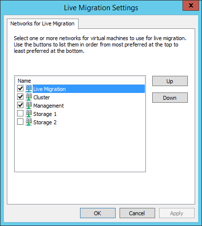
The tree node itself has only a single unique item: Live Migration Settings. The others are the standard View, Refresh, and Help items. Clicking the Live Migration Settings item will display a dialog box similar to the following:
This dialog allows you to prioritize how Live Migration will utilize available networks. It should be used judiciously to prevent Live Migrations from drowning out other types of communication. Live Migration traffic will only be allowed on networks that are checked (those networks must also be marked to allow cluster traffic, which will be demonstrated shortly). Items at the top of the dialog will be given preference when networks are selected. If the sending and receiving nodes are both set to use SMB for Live Migration and SMB multichannel is active, all selected networks will carry Live Migration traffic.
Networks List Entries and Context Menus
The center pane of the Networks section of Failover Cluster Manager looks like the following:
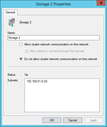
The upper portion shows the name, status, and allowed traffic for each network. The context menu for these items contains only three entries: Information Details, Show Critical Events, and Properties. As is common to previously discussed objects in Failover Cluster Manager, the Information Details link shows a pop-up dialog with details about any error message caused in this session and Show Critical Events displays any error events involving the selected item. Properties opens the properties dialog for the item:
The first changeable control is the name. A network can be safely renamed at any time. The most common use of this feature is to give a meaningful description to the network.
The second control group indicates how the network is to be used.
Allow cluster network communication on this network grants the ability for cluster communications, such as heartbeat, Redirected Access, and Live Migrations to utilize the selected network.
Allow clients to connect through this network is not as meaningful in a Hyper-V cluster as for other cluster types. The network that the cluster name object (CNO) appears on should be marked for client access. Clustered Hyper-V does not expose its virtual machine roles through this network the way that other clustered roles do, so this check box serves no other purpose.
Do not allow cluster network communication on this network prohibits the cluster from using the network at all. This will prevent Live Migration traffic even if the network’s box is checked for Live Migration as shown in the preceding sub-section.
The remainder of this dialog shows the status of the network and the subnets that have been detected on it.
Details Pane
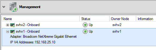
The initial dialog for this section showed the Summary pane for the details section. It displays the name of the network and its detected subnets. There is also a Network Connections tab which shows the adapters in the subnet:
If a network is partitioned, this can help you determine which node(s) have lost connectivity or have failed adapters. It can also help you to verify that adapters have been assigned to the correct subnet. The displayed name (Onboard in the above image) is the same name that the host’s management operating system shows for the adapter. These items have a context menu with the options Information Details and Show Critical Events.
Cluster Events
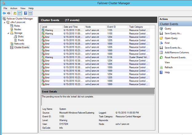
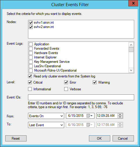
The final cluster tree node is Cluster Events. This contains a display that is very similar to that of the standard Windows Event Viewer. It has been automatically filtered to contain a specific subset of the cluster-related events. Not all possible events are shown. The default view appears below:
The Cluster Events node does have a context menu, displayed on the right in the above screenshot. It will not be discussed in detail here, as it is quite similar to that found in the traditional Event Viewer. One item to point out to those that are not familiar with that interface is Query. Clicking this will show the following dialog, which you can use to tailor what appears here:
Other items in the context menu can be used to further manipulate the query, if you so desire.
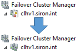
A second notable item in this list is Reset Recent Events. This clears the view, but it does not remove the events themselves. It also has the effect of resetting the icon that Failover Cluster uses for the cluster back to its default as shown below:
Wrapping up in the GUI
This concludes the tour of Failover Cluster Manager and the unit on the built-in graphical tools to manage Hyper-V and Failover Clustering. These sections have taken a very thorough look at these tools and their capabilities and will serve as a reference as you work through the rest of the material and in into the future.


 > Mail > POP and IMAP.